1
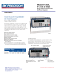
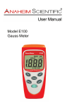
Model: 601B SLA Battery Capacity Analyzer USER MANUAL Safety Summary The following safety precautions apply to both operating and maintenance personnel and must be followed during all phases of operation, service, and repair of this instrument. Before applying power to this instrument: • Read and understand the safety and operational information in this manual. • Apply all the listed safety precautions. • Verify that the voltage selector at the line power cord input is set to the correct line voltage. Operating the instrument at an incorrect line voltage will void the warranty. • Make all connections to the instrument before applying power. • Do not operate the instrument in ways not specified by this manual or by B&K Precision. Failure to comply with these precautions or with warnings elsewhere in this manual violates the safety standards of design, manufacture, and intended use of the instrument. B&K Precision assumes no liability for a customer’s failure to comply with these requirements. Category rating The IEC 61010 standard defines safety category ratings that specify the amount of electrical energy available and the voltage impulses that may occur on electrical conductors associated with these category ratings. The 2 category rating is a Roman numeral of I, II, III, or IV. This rating is also accompanied by a maximum voltage of the circuit to be tested, which defines the voltage impulses expected and required insulation clearances. These categories are: Category I (CAT I): Measurement instruments whose measurement inputs are not intended to be connected to the mains supply. The voltages in the environment are typically derived from a limited-‐energy transformer or a battery. Category II (CAT II): Measurement instruments whose measurement inputs are meant to be connected to the mains supply at a standard wall outlet or similar sources. Example measurement environments are portable tools and household appliances. Category III (CAT III): Measurement instruments whose measurement inputs are meant to be connected to the mains installation of a building. Examples are measurements inside a building's circuit breaker panel or the wiring of permanently-‐installed motors. Category IV (CAT IV): Measurement instruments whose measurement inputs are meant to be connected to the primary power entering a building or other outdoor wiring. Do not use this instrument in an electrical environment with a higher category rating than what is specified in this manual for this instrument. 3 You must ensure that each accessory you use with this instrument has a category rating equal to or higher than the instrument's category rating to maintain the instrument's category rating. Failure to do so will lower the category rating of the measuring system. Do not operate in an explosive or flammable atmosphere Do not operate the instrument in the presence of flammable gases or vapors, fumes, or finely-‐divided particulates. The instrument is designed to be used in office-‐type indoor environments. Do not operate the instrument • In the presence of noxious, corrosive, or flammable fumes, gases, vapors, chemicals, or finely-‐divided particulates. • In relative humidity conditions outside the instrument's specifications. • In environments where there is a danger of any liquid being spilled on the instrument or where any liquid can condense on the instrument. • In air temperatures exceeding the specified operating temperatures. • In atmospheric pressures outside the specified altitude limits or where the surrounding gas is not air. • In environments with restricted cooling air flow, even if the air temperatures are within specifications. • In direct sunlight. 4 This instrument is intended to be used in an indoor pollution degree 2 environment. The operating temperature range is 0 °C to 40 °C and the operating humidity range is ≤ 95% relative humidity with no condensation allowed. Measurements made by this instrument may be outside specifications if the instrument is used in non-‐office-‐ type environments. Such environments may include rapid temperature or humidity changes, sunlight, vibration and/or mechanical shocks, acoustic noise, electrical noise, strong electric fields, or strong magnetic fields. Do not operate instrument if damaged If the instrument is damaged, appears to be damaged, or if any liquid, chemical, or other material gets on or inside the instrument, remove the instrument's power cord, remove the instrument from service, label it as not to be operated, and return the instrument to B&K Precision for repair. Notify B&K Precision of the nature of any contamination of the instrument. Clean the instrument only as instructed Do not clean the instrument, its switches, or its terminals with contact cleaners, abrasives, lubricants, solvents, acids/bases, or other such chemicals. Clean the instrument only with a clean dry lint-‐free cloth or as instructed in this manual. Not for critical applications 5 This instrument is not authorized for use in contact with the human body or for use as a component in a life-‐ support device or system. Do not touch live circuits Instrument covers must not be removed by operating personnel. Component replacement and internal adjustments must be made by qualified service-‐trained maintenance personnel who are aware of the hazards involved when the instrument's covers and shields are removed. Under certain conditions, even with the power cord removed, dangerous voltages may exist when the covers are removed. To avoid injuries, always disconnect the power cord from the instrument, disconnect all other connections (for example, test leads, computer interface cables, etc.), discharge all circuits, and verify there are no hazardous voltages present on any conductors by measurements with a properly-‐operating voltage-‐sensing device before touching any internal parts. Verify the voltage-‐sensing device is working properly before and after making the measurements by testing with known-‐operating voltage sources and test for both DC and AC voltages. Do not attempt any service or adjustment unless another person capable of rendering first aid and resuscitation is present. Do not insert any object into an instrument's ventilation openings or other openings. Servicing 6 Do not substitute parts that are not approved by B&K Precision or modify this instrument. Return the instrument to B&K Precision for service and repair to ensure that safety and performance features are maintained. For continued safe use of the instrument • Do not place heavy objects on the instrument. • Do not obstruct cooling air flow to the instrument. • Do not place a hot soldering iron on the instrument. 7 Table of Contents Section 1 General Description ................................................................................................................................. 9 1.1 INTRODUCTION ............................................................................................................................................. 9 1.2 APPLICATIONS ............................................................................................................................................... 9 1.3 SPECIFICATIONS ............................................................................................................................................. 9 Section 2 Operation .............................................................................................................................................. 10 2.1 Front Panel Controls .................................................................................................................................... 10 2.2 Operating Procedure ................................................................................................................................... 11 Service Information .............................................................................................................................................. 14 Limited One-‐Year Warranty ................................................................................................................................. 15 8 Section 1 General Description 1.1 INTRODUCTION B&K Precision Battery Capacity Analyzer Model 601B measures the terminal voltage, internal resistance, and percent of charged capacity left in a battery. The model 601B supports 6V & 12V storage type lead acid batteries with wide range of Ah capacity. No external power (Mains or DC) is required. The unit w orks o n the BUT (Battery U nder Test) p ower. 1.2 APPLICATIONS As the information age develops it is likely that the demand for UPS units will increase for use in hospitals, offices, labs etc. It is expected that the importance of battery maintenance will increase along with increasing demand for UPS. The 601B can be applicable for Automobile Service Stations, UPS Manufacturing, Maintenance and Field Servicing, QC Department, Battery Systems in Railways, Telecommunications, Ships / Submarine. 1.3 SPECIFICATIONS Voltage R anges: 6V, 12V automatically selected Display: i) C apacity 0% t o 100%. ii) No l oad Voltage & l oaded Voltage. iii) Internal R esistance. Min. Input Voltage: 4 .8V NOTE: Specifications and information are subject to change without notice. Please visit www.bkprecision.com for the most current product information. Max. Input Voltage: 20V Measurable A h S election: Programmable 5-‐100Ah in steps of 1Ah. No Load Voltage Accuracy: ± 0.2% ± 1 counts. Voltage Resolution: 1 0mV. Dimensions ( WxHxD): 2.91 x 1 0.44 x 2.28” ( 74 x 2 6 5 . 1 x 5 8 m m ) Weight: 2.65lb ( 1.2 kg) 9 Section 2 Operation 2.1 Front Panel Controls 1. 2. 3. 4. 5. 6. 7. 8. 9. Power / Select: Powers on unit after connecting to BUT. Also used to select Ah seting. After activation user can select the Ah values as per BUT rating using this key. Up: This key is used to increase the Ah values. Down: With this key, the user can decrease the Ah values. Test: On pressing this key the measurement will begin. Repeat Test: This key is used to repeat previously performed test. Reverse Polarity LED: This LED glows when the battery is reverse connected. LCD : This is 16x2 line alphanumeric display. It displays various messages & results of tests as per Ah value selected. -‐ve Cable: Negative connecting cable with strain relief. +ve Cable: Positive connecting cable with strain relief. 10 2.2 Operating Procedure Follow the steps as outlined below: 2.2.1 Connection Procedure Connect Battery Capacity Analyzer (601B) to Battery Under Test (BUT). Connect the +ve terminal of 601B to +ve terminal of Battery. Connect -‐ve terminal of 601B to -‐ve terminal of Battery. The 601B will be powered by the BUT. To power on the unit, press & hold the POWER key. On Power up, 601B performs a memory test & displays open circuit voltage on LCD. CAUTION : Do not connect the +ve terminal of 601B to -‐ve terminal of BUT and -‐ve terminal of 601B to +ve terminal of BUT. On doing so, the 'Reverse Polarity' LED glows. 2.2.2 Operation Procedure On Power up, following screens will appear. BK-‐PRECISION BK-‐601B Next the unit goes the memory test. Following message will be displayed. MEMORY TEST…… If memory test is OK. FOUND PREVIOUS SETTINGS If the memory test fails: NO SETTINGS FOUND LOADING DEFAULTS If the flash memory is corrupted, following Message is displayed: 11 INT MEMORY ERROR LOADING DEFAULTS Next screen directs the user to the menu to select the sub-‐menu. The battery is auto-‐sensed & the defaults are loading accordingly. After memory test, the open circuit voltage is displayed on the first line of LCD, the required Ah value can be selected using up & down keys. OPEN CKT: 12.53V SELECT Ah: 028 On selecting the required Ah value, press Select Ah & then press the TEST key, the measurements will begin & following message is displayed. Backlight will switch off during the test. TEST INPROGRESS 12.53V 028AH The results will be displayed as follows. 12.37V 61.87%CAP IR: 39.2 m Ohm The first field indicates the battery terminal voltage when battery was loaded during the test; the second field shows the balance capacity in percentage. IR indicates the internal resistance in milli-‐ohms. After the test, follows a cooling period of approximately 15 seconds. If user tries to perform a test during this period, the following message is displayed. TO BEGIN N EXT SESSION, W AIT…. In case the open circuit voltage of BUT exceeds 14.8V, the following screen will be continuously flashed & you will not be able to enter the test mode. X H IGH V OLTAGE X REMOTE BATTERY 12 Once the test period elapses the following screen will be displayed. OPEN CKT: 12.53V SELECT A h: 028 To start a new test, press SELECT Ah key & in order to repeat the same test, press TEST REPEAT key. To prevent unnecessary discharge of BUT, the unit will switch off automatically after 5 minutes of non-‐operational period. 1) Do not connect Model 601B to a voltage source more than 20V. 2) Do not connect the unit to a battery connected in circuit. 13 Service Information Warranty Service: Please go to the support and service section on our website at www.bkprecision.com to obtain a RMA #. Return the product in the original packaging with proof of purchase to the address below. Clearly state on the RMA the performance problem and return any leads, probes, connectors and accessories that you are using with the device. Non-‐Warranty Service: Please go to the support and service section on our website at www.bkprecision.com to obtain a RMA #. Return the product in the original packaging to the address below. Clearly state on the RMA the performance problem and return any leads, probes, connectors and accessories that you are using with the device. Customers not on an open account must include payment in the form of a money order or credit card. For the most current repair charges please refer to the service and support section on our website. Return all merchandise to B&K Precision Corp. with prepaid shipping. The flat-‐rate repair charge for Non-‐Warranty Service does not include return shipping. Return shipping to locations in North America is included for Warranty Service. For overnight shipments and non-‐North American shipping fees please contact B&K Precision Corp. B&K Precision Corp. 22820 Savi Ranch Parkway Yorba Linda, CA 92887 www.bkprecision.com 714-‐921-‐9095 Include with the returned instrument your complete return shipping address, contact name, phone number and description of problem. 14 Limited One-‐Year Warranty B&K Precision Corp. warrants to the original purchaser that its products and the component parts thereof, will be free from defects in workmanship and materials for a period of one year from date of purchase. B&K Precision Corp. will, without charge, repair or replace, at its option, defective product or component parts. Returned product must be accompanied by proof of the purchase date in the form of a sales receipt. To help us better serve you, please complete the warranty registration for your new instrument via our website www.bkprecision.com Exclusions: This warranty does not apply in the event of misuse or abuse of the product or as a result of unauthorized alterations or repairs. The warranty is void if the serial number is altered, defaced or removed. B&K Precision Corp. shall not be liable for any consequential damages, including without limitation damages resulting from loss of use. Some states do not allow limitations of incidental or consequential damages. So the above limitation or exclusion may not apply to you. This warranty gives you specific rights and you may have other rights, which vary from state-‐to-‐state. B&K Precision Corp. 22820 Savi Ranch Parkway Yorba Linda, CA 92887 www.bkprecision.com 714-‐921-‐9095 15 B&K Precision Corporation 22820 Savi Ranch Parkway Yorba Linda, California 92887 www.bkprecision.com ©2015 B&K Precision Corporation Printed in Taiwan 082615 16