1
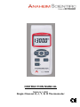
INSTRUCTION MANUAL Models: H200 Single Channel K, J, T, E, R Thermometer Table of Content 1. Product Introduction ………………………………………… 3 1-1 Features ………………….………………………… 3 1-2 Applications ……………………………………...… 3 2. Safety Information …………………………………………… 4 2-1 Cautions ………………………………..………..… 4 2-2 Safety Symbols ………………………..…..……… 4 3. Specifications……………………………………...…………. 5 4. Operation Instructions……………………………………… 4-1 Unit Diagram ……………………………………… 4-2 Measuring Procedure ……………………….…... 4-3 Thermocouple Measuring Procedure ……………… 4-4 Offset Value Adjustment ……..………….………… 4-5 Measuring Considerations ……....………………… 4-6 Data Hold Mode …………………………………… 4-7 Rec Mode ………………………………………… 4-8 REL Mode ……………………………………….. 6 6 7 7 7 7 7 7 8 5. Auto Power Off Disable …………………………………… 8 6. RS232 PC Serial Interface Information …………………. 9 7. Battery Replacement ..…………………………………….. 11 8. Service Information …………………………………..……. 12 9. Warranty Information ………………………………………. 13 To see all available accessories and downloadable software, please visit www.anaheimscientific.com 1. Product Introduction 1-1 Features Measures temperature fro m five different types of thermocouples 0.1 Resolution Fast response ti me High level of accuracy Large LCD display Two year warranty 1-2 Applications Science Experiments HVAC Plant Maintenance Manufacturing Agriculture Quality Control 2. Safety Information Read the follow ing safety information carefull 3 y before attempting to operate or serv ice the meter. Only qualified personnel should perform repairs or serv ic ing not cov ered in this manual. 2-1 Cautions! DO NOT submerge the products mentioned in this manual in w ater or any other ty pes of liquids. This product is not designed for use in medical applications. The product can only be used to measure body temperature simply for reference. 2-2 Safety Symbols Dangerous, refer to this manual before using the meter. Conforms to requirements of European Union and European Fare Trade Association (EFTA). Battery lev el is low. Don’t dispose this product as unsorted municipal waste. This instrument conforms to the follow ing standards: EN61326: Electrical equipment for measurement, control and laboratory use. IEC61000-4-2: Electrostatic discharge im munity test. IEC61000-4-3: Radiated, radio-frequency, electromagnetic field im munity test. IEC61000-4-8: Power frequency magnetic field immunity test. 4 3. Specifications Unit of Measurement Temperature Compensation Thermocouple Types Thermocouple Type °C or °F Automatic for cold junction on K & J type K, J, T, E & R Resolution 0.1°C Type K 0.1°F 0.1°C Type J 0.1°F 0.1°C Type T 0.1°F 0.1°C Type E 0.1°F 1°C Type R 1°F Data Hold Memory Sampling Time Range -50.0 to 1300.0°C -50.1 to -100.0°C -58.0 to 2372.0°F -58.1 to -148.0°F -50.0 to 1150.0°C -50.1 to -100.0°C -58.0 to 2102.0°F -58.1 to -148.0°F -50.0 to 400.0°C -50.1 to -100.0°C -58.0 to 752.0°F -58.1 to -148.0°F -50.0 to 900.0°C -50.1 to -100.0°C -58.0 to 1652.0°F -58.1 to -148.0°F 0 to 600°C 601 to 1700°C 32 to 1112°F 1113 to 3092°F Accuracy* +( 0.2 % + 0.5°C ) +( 0.2 % + 1°C ) +( 0.2 % + 1°F ) +( 0.2 % + 1.8°F ) +( 0.2 % + 0.5°C ) +( 0.2 % + 1°C ) +( 0.2 % + 1°F ) +( 0.2 % + 1.8°F ) +( 0.2 % + 0.5°C ) +( 0.2 % + 1°C ) +( 0.2 % + 1°F ) +( 0.2 % + 1.8°F ) +( 0.2 % + 0.8°C ) +( 0.2 % + 1°C ) +( 0.2 % + 1.5°F ) +( 0.2 % + 1.8°F ) +( 1 % + 5°C ) +( 1.5 % + 5°C ) +( 1 % + 10°F ) +( 1.5 % + 10°F ) Display freeze Saves MAX. or MIN values with recall Approximately 1 second " --- - " RS-232 Serial data output 32° to 122°F (0° to 50°C), <80% R.H. 6 Pieces of DC 1.5V Batteries (UM4, AAA or Power Supply equivalent) Weight (approx.) 0.62lbs. (280g) Dimensions (approx.) 6.9 x 2.7 x 1.7" (174 x 68 x 42mm) Included Accessories Instruction manual, battery, carrying case * = Note : Accuracy applicable in environments with temperatures between 20°C to 26°C and only applies to the meter itself, not the probe. Specifications and information are subject to change without notice Please visit www.anaheimscientific.com for the most current product information. Over Range Indicator Data Output Operating Environment 5 4. Operating Instructions 4-1 Unit Diagram Fig. 1 4-1 4-2 4-3 4-4 4-5 4-6 4-7 Display Power Button Hold Button REC (MAX/MIN ) Button Sensor Button REL () Button C°/F° () Button 4-8 RS232 Socket 4-9 Battery Compartment 4-10 Thermocouple Input Socket 4-11 Stand 4-13 Tripod Screw Mount 4-12 Battery Cover Screw 6 4-2 Measuring Procedure 4-3 Thermocouple Measuring Procedure 1. Power on the meter by pressing the “ Power Button” (4-2, Fig. 1). The meter will go through a short self test. 2. Select the sensor type by pressing the “ Sensor Button” (4-5, Fig.1). As you press this button multiple time the meter will display the sensor type along the bottom of the LCD. You will see it change between K, J, T, E & R. 3. Once you have set it for the desired sensor type, insert the probe in to the “ Thermocouple Input Socket” (4-10, Fig. 1). 4. Select the unit of measure by pressing the “ °C/°F Button” (4-7, Fig.1). 5. Insert the Thermocouple in to the environment you wish to measure. The LCD will display the measured values. 4-4 Offset Value Adjustment In some environments or applications there may be some need to offset the displayed temperature value. After following section 4-3 follow these steps to set a offset value. 1. Simultaneously press and hold the “Hold Button” (4-3, Fig. 1) and “ REC Button” (4-4, Fig.1). 2. The LCD will display the starting value in the bottom of the LCD and the value in the middle section. 3. Using the “ Up Button” (4-7, Fig. 1) to increase the offset value and/or the “ Down Button” (4-6, Fig.1) to decrease the offset value. 4. Release all buttons to go to the normal measurement screen. The meter will now display measured values with the offset already calculated in to the reading. 4-5 Measuring Considerations 1. When in serting the measurement probes in to the “ Thermocouple Input Socket” (4-10, Fig. 1), note the correct polarity usually indicated by the size of the plug blades (negative usually being the wider of the two). 2. For the most accurate reading allow the probe to stabilize when it is being introduced in to an environment that is significantly different in temperature from its starting point. 4-6 Data Hold Mode 1. During a measurement, press the “ Hold Button” (4-3, Fig. 1) to hold the displayed value on the LCD. The “ HOLD” symbol will also be displayed on the LCD. 2. Pressing the “ Hold Button” (4-3, Fig. 1) will release the data hold function. 4-7 REC Mode 1. To record the maximum and minimum readings, press the “ REC Button” (4-4, Fig. 1). The REC symbol will be displayed on the LCD. By pressing the “ REC Button” (4-4, Fig. 1) you can toggle through the Max and Min values. 2. To stop using the REC function, press and hold the “ REC Button” (4-4, Fig. 1) for at least 3 seconds. 7 4-8 REL Mode 1. It is recommended that you memorize the value on the LCD display first. Also note that the REL function does not work when the meter is in Data Hold or Data Record conditions. 2. To remove any displayed value from the LCD you can press the “ REL Button” (4-6, Fig. 1). The display will then go to zero and you will see the REL marker in the top portion. 3. All subsequent values displayed will be the measured value minus the amount on the display when the REL button was pressed. 4. To cancel the REL function, simply press the “ REL Button” (4-6, Fig. 1). The REL marker will then disappear from the LCD. 5. Auto Power Off Disable This instrument has a “ Auto Power Off " function that can prolong battery life. The meter will shut off automatically if none of the buttons are pressed in approx. 10 min. To disable this function, select the memory record function during a measurement by pressing the " REC. Button” (4-4, Fig. 1 ). 8 6. RS232 PC Serial Interface Information This instrument has RS232 PC serial interface via a 3.5 mm terminal (4-12, Fig. 1). The data output is a 16 digit stream which can be utilized for user's specific application. A RS232 lead with the following connection will be required to link the instrument with the PC serial port. Visit www.anaheimscientific.com to see any available downloadable software for your instrument. 9 The 16 digit data stream will be displayed in the following format: D15 D14 D13 D12 D11 D10 D9 D8 D7 D6 D5 D4 D3 D2 D1D0 Each digit indicates the following status: D15 Start Word D14 4 D13 1 D12 & D11 Indicator for Display °C = 01 °F = 02 D10 Polarity: 0 = Positive / 1 = Negative Decimal Point (DP), position from right to left D9 0 = No DP, 1 = 1 DP, 2 = 2 DP, 3 = 3 DP Display reading, D1 = LSD, D8 = MSD Example: If the display reading is 1234, D8 to D1 then D8 to D1 is: 00001234 D0 End Word RS232 Setting Baud Rate Parity Data bit # Stop bit 9600 No Parity 8 Data bits 1 Stop bit 10 7. Battery Replacement 1. When the LCD dis play shows the “ ” low battery symbol, It is necessary to replace the battery. The specifications listed for this instrument do not apply when the low battery symbol is displayed. 2. Open the “Battery Compartment” (4-9, Fig. 1) by first loosening the “Battery Cover Screw s” (4-12, Fig. 1). 3. Replace the batteries with “good” batteries noting the correct polarity . Replace “Battery Compartment” (4-9, Fig. 1) and “Battery Cover Screws” (4-12, Fig. 1). Ensure the cov er is securely fastened. 11 8. Service Inform ation Warranty Service: Please return the product in the original packaging with proof of purchase to the address below . Clearly state in writing the performance problem and return any leads, probes, connectors and accessories that you are using w ith the device. Non-Warranty Service: Return the product in the original packaging to the address below . Clearly state in w riting the performance problem and return any leads, probes, connectors and accessories that you are using w ith the device. Customers not on open account must include payment in the form of a money order or credit card. For the most current repair charges please visit www.anaheimscientific.com and click on “service/repair”. Return all merchandise to Anaheim Scientific w ith pre-paid shipping. The flat-rate repair charge for Non-Warranty Service does not include return shipping. Return shipping to locations in North A merican is included for Warranty Service only. For overnight shipments and nonNorth American shipping fees please contact Anaheim Scientific. Anaheim Scientific 22820 Savi Ranch Par kw ay Yorba Linda, CA 92887 www.anaheimscientific.com 714-921-9095 Include with the returned instrument your com plete return shipping address, contact name, phone number and description of problem . 12 9. Lim ited Two-Year Warranty Anaheim Scientific w arrants to the original purchaser that its products and the component parts thereof, w ill be free from defects in workmanship and materials for a period of tw o years from date of purchase from an authorized Anaheim Scientific distributor. Anaheim Scientific w ill, w ithout charge, repair or replace, at its option, defective product or component parts. Returned product must be accompanied by proof of the purchase date in the form of a sales receipt. To obtain w arranty coverage in the U.S.A., this product must be registered by completing the w arranty registration form on www.anaheimscientific.com w ithin fifteen (15) days of purchase. Exclusions: This w arranty does not apply in the event of m isuse or abuse of the product or as a result of unauthorized alterations or repairs. The w arranty is void if the serial number is altered, defaced or rem oved. Anaheim Scientific shall not be liable for any consequential damages, including w ithout limitation damages resulting from loss of use. Some states do not allow limitations of incidental or consequential damages. So the above limitation or exclusion may not apply to you. This w arranty gives you specif ic rights and you may have other rights, which vary from state-to-state. Anaheim Scientific 22820 Savi Ranch Par kw ay Yorba Linda, CA 92887 www.anaheimscientific.com 714-921-9095 13 Anaheim Scientific 22820 Savi Ranch Par kw ay Yorba Linda, CA 92887 U.S.A. www.anaheimscientific.com Printed in Taiw an / Ver. 1.0/0606 © 2006 Anaheim Scientific Corporation