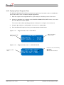
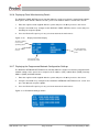
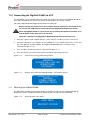
1
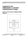
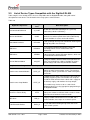
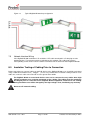
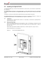
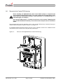
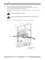
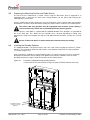
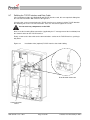
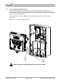
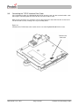
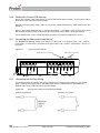
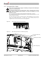
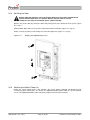
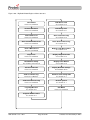
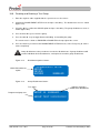
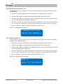
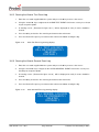
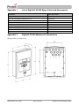
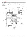
Digilite® DL500
EMERGENCY LIGHTING
SUPERVISORY PANEL
INSTALLATION AND COMMISSIONING
MANUAL
Protec Fire Detection plc, Protec House, Churchill Way, Nelson, Lancashire, BB9 6RT, ENGLAND
+44 (0) 1282 717171
www.protec.co.uk
[email protected]
Document Revision Details
Issue
1
Modification Detail
Document Creation
N93-582-01 Issue 1 NH
Author
NH
Page 2 of 42
Date
05/02/2015
© Protec Fire Detection plc 2015
Table of Contents
IMPORTANT NOTES – PLEASE READ CAREFULLY ................................................................................... 5
1.0
GLOSSARY OF TERMS ........................................................................................................................ 6
2.0
LIST OF DEVICE TYPES COMPATIBLE WITH THE DIGILITE® DL500............................................. 7
3.0
ITEMS SUPPLIED WITH THE DIGILITE® DL500................................................................................. 8
4.0
ITEMS AND INFORMATION REQUIRED PRIOR TO COMMISSIONING ............................................ 8
4.1
4.2
Site information required to commission the Digilite® DL500 ......................................................... 8
Items required to commission the Digilite® DL500 using the Windows Configuration Tool ........... 8
5.0
INTRODUCTION AND KEY FEATURES .............................................................................................. 9
6.0
KEY FEATURES AND BENEFITS ........................................................................................................ 9
7.0
DIGILITE® DL500 CABLING REQUIREMENTS................................................................................. 10
7.1
7.2
7.3
7.4
7.5
General .......................................................................................................................................... 10
Mains Input Rating Label ............................................................................................................... 10
Mains Wiring .................................................................................................................................. 10
Addressable Loop Wiring and Devices ......................................................................................... 10
Network Interface Wiring ............................................................................................................... 11
8.0
INSULATION TESTING OF CABLING PRIOR TO CONNECTION .................................................... 11
9.0
INSTALLING THE DIGILITE® DL500 ................................................................................................. 12
9.1
9.2
9.3
9.4
9.5
9.6
9.7
9.8
9.9
9.10
9.11
9.12
9.13
9.14
9.15
10.0
Unpacking ...................................................................................................................................... 12
Removal of the Door ...................................................................................................................... 12
Removal of the Control PCB Housing ........................................................................................... 13
Removal of the optional TCP/IP Interface PCB and Data Cable .................................................. 14
Preparing the Mounting Position and Cable Entries...................................................................... 15
Installing the Standby Batteries ..................................................................................................... 15
Refitting the TCP/IP Interface and Data Cable.............................................................................. 16
Connecting the Standby Batteries ................................................................................................. 17
Connecting the TCP/IP Interface Data Cable................................................................................ 18
Refitting the Control PCB Housing ............................................................................................ 19
Connecting the Addressable Loop Wiring ................................................................................. 19
Connecting the Auxiliary Wiring ................................................................................................. 19
Connecting the Mains Cabling ................................................................................................... 20
Re-fitting the Door ...................................................................................................................... 21
Switching the Mains Power On .................................................................................................. 21
COMMISSIONING THE DIGILITE® DL500 ..................................................................................... 22
10.1
10.2
10.3
10.4
10.5
10.6
10.7
10.8
10.9
10.10
10.11
10.12
10.13
10.14
10.15
10.16
10.17
Loop Device Test Group Programming ..................................................................................... 22
Grouping Considerations For Central Systems ......................................................................... 22
Sub Circuit Monitoring for Central Systems ............................................................................... 22
Global Fault Contact Operation ................................................................................................. 22
Control Input 1 and 2 operation ................................................................................................. 22
Logging Loop Devices ............................................................................................................... 24
Programming Loop Device Address Data ................................................................................. 25
Disabling and Enabling an Individual Device ............................................................................. 26
Disabling and Enabling a Test Group ........................................................................................ 27
Editing Device Location Text ..................................................................................................... 28
Editing Group Text ..................................................................................................................... 28
Clearing the Historic Test Event Log ......................................................................................... 29
Clearing the Historic General Event Log ................................................................................... 29
Displaying Loop Device Data ..................................................................................................... 30
Displaying Panel Diagnostic Data .............................................................................................. 31
Displaying Panel Manufacturing Details .................................................................................... 32
Displaying the Programmed Network Configuration Settings .................................................... 32
N93-582-01 Issue 1 NH
Page 3 of 42
© Protec Fire Detection plc 2015
11.0
CONNECTING THE DIGILITE® DL500 TO A PC ........................................................................... 33
11.1
Restarting the Digilite® DL500 .................................................................................................. 33
12.0
PROGRAMMING THE SYSTEM USING THE WINDOWS CONFIGURATION TOOL ................... 34
13.0
GENERAL SYSTEM OPERATION .................................................................................................. 34
13.1
14.0
Added Loop Devices .................................................................................................................. 34
DIGILITE® DL500 TECHNICAL SPECIFICATION .......................................................................... 35
APPENDIX 1
LIST OF DIGILITE® DL500 SPARE PARTS AND ACCESSORIES ................................ 37
APPENDIX 2
DIGILITE® DL500 MECHANICAL DIMENSIONS ............................................................. 37
APPENDIX 3
DIGILITE® DL500 CONTROL PCB HOUSING ................................................................. 38
APPENDIX 4
DIGILITE® DL500 EVENT DESCRIPTIONS ..................................................................... 39
N93-582-01 Issue 1 NH
Page 4 of 42
© Protec Fire Detection plc 2015
Important Notes – PLEASE READ CAREFULLY
•
This manual and the Digilite® DL500 User Manual must be thoroughly read and
understood before commissioning is undertaken.
•
The Digilite® DL500 and its associated connections must be installed,
commissioned and maintained by a suitably trained, skilled and competent
person.
•
It is assumed that the person installing and commissioning the system is familiar
with Protec Fire Detection plc equipment terminology and terms of reference.
•
This equipment must be earthed and earth continuity must be preserved on
broken segments of screened cable used anywhere in the system installation.
•
This equipment is not guaranteed unless installed and commissioned in
accordance with current national standards.
•
This equipment WILL NOT operate as an automatic testing system when the USB
port is connected and is in commissioning mode.
•
This equipment is not suitable as part of an I.T type power distribution system as
defined in IEC 60364-3.
•
It is perfectly normal for sealed lead acid batteries to vent small amounts of
hydrogen when being charged. The Digilite® DL500 is vented to dissipate any
build up of hydrogen. The enclosure must not be not sealed in any way.
•
A competent person trained to undertake such work MUST carry out any internal
maintenance. There are no user serviceable parts inside the Digilite® DL500.
•
Opening the PCB housing will immediately invalidate any warranty.
There are no user serviceable parts inside the Digilite® DL500. A competent person trained to
undertake such work MUST carry out any internal maintenance work. A separate installation
and commissioning manual is available.
This equipment has been manufactured in conformance with the requirements of all applicable EU
council directives.
The policy of Protec Fire Detection plc is one of continuous improvement and as such we reserve the right
to make changes to product specifications at any time and without prior notice. Errors and omissions
excepted.
Electrical or electronic devices that are no longer serviceable must be collected separately and
sent for environmentally compatible recycling (in accordance with the European Waste
Electrical and Electronic Equipment Directive). To dispose of old electrical or electronic
devices, you should use the return and collection systems put in place in the country
concerned.
Digilite® is a registered trademark of Protec Fire Detection plc.
N93-582-01 Issue 1 NH
Page 5 of 42
© Protec Fire Detection plc 2015
1.0
Glossary of Terms
‘Digilite® DL500’ or ‘panel’
Refers to the Digilite® DL500 Emergency Lighting Supervisory Control Panel.
Downloading
Refers to the transfer of data from a PC to the Digilite® DL500.
Uploading
Refers to the transfer of data from the Digilite® DL500 to a PC.
Site-file
Refers to the site configuration data file that is stored in the Digilite® DL500, this file contains the data about
loop devices, panel settings, loop device text, group text, panel text and test duration and time. When this file
is uploaded using the Windows Configuration Tool any historic event logs are automatically appended to it.
Loop
The two wire power and data connections which the Digilite® DL500 uses to control and interrogate any
devices.
'Device' or 'Address'
A luminaire or interface connected to the Digilite® DL500 loop which can be controlled by and transmits data
to the Digilite® DL500.
Type
Each address on the Digilite® DL500 loop may be assigned a type by the PC commissioning software. The
type changes how the Digilite® DL500 controls and interprets data from the device.
Group
Individual luminaire addresses may be programmed into one of 28 groups. This is done to ensure that
emergency lighting coverage is maximised when luminaires are being tested (adjacent luminaires are usually
programmed into different groups). Testing is performed on a group basis.
Maintained luminaire
A light fitting which is always illuminated, either from a local mains supply, or from a backup supply if the
local mains supply fails.
Non-maintained luminaire
A light fitting which only illuminates using a backup supply when the mains supply to it is disconnected.
Disablement
When a device, or group is disabled it is prevented from entering test mode and cannot generate faults, or
failed tests.
Sub Circuit
Some Digilite® DL500 fittings can be set to monitor the state of their local mains connection, and report this
back to the Digilite® DL500. The mains supply monitored by these fittings may differ from the mains
supplying the Digilite® DL500 itself, and is termed a 'Sub Circuit'.
Historic Event log
A chronological record of salient events on the system (e.g. group tests, luminaire failures etc).
Central system
A Central Battery or Static Inverter system which uses a centralised power source to feed slave lighting, as
opposed to the lighting having its own local battery.
Slave Interface
An interface designed to monitor the status of a lamp, usually used on central systems. This interface
generally has no control functionality.
N93-582-01 Issue 1 NH
Page 6 of 42
© Protec Fire Detection plc 2015
2.0
List of Device Types Compatible with the Digilite® DL500
Table 2.0 gives a list of loop devices that are compatible with the Digilite® DL500 , along with a brief
description of each device. For full details of the range please contact Protec.
Table 2.0.
Digilite® Loop Device
Self Contained Bulkhead
Conversion Module
Panel Type
Text
S_CONT
CONV
Brief Description
An 8W non LED bulkhead fitting that is generally
powered by a local 2 cell battery.
A module which is incorporated into third party
luminaires in order to permit them to be automatically
tested. Available in 2,3,4,5 and 6 cell variants.
Powerflood Luminaire
PFLOOD
A twin spot high intensity non-maintained unit designed
for high bay wide area coverage.
LED Driver
LEDDRV
A self contained bulkhead luminaire using LED
technology which can be maintained or nonmaintained.
LED Ballast
LEDBAL
A driver for higher power LED down lighters, which can
be maintained or non-maintained.
Current Monitor Module
CM_INT
A range of modules which monitor and report back the
mains current drawn by a fitting. Available in various
current ratings and in AC only and AC/DC models.
Loop Interfaces Designed for Central Systems
Static Inverter Control Module
Static Inverter Loop Module
STAT_CT
STAT_LP
A module that fits within and interfaces to a Central
Battery or Static Inverter power source. The interface
can put the central system into 'test' mode and reports
back faults.
A module that fits within each luminaire connected to a
centrally supplied system. The module can swap the
feed to the local luminaire from a local mains supply to
the backup supply, and monitors the lamp output.
This module may also be used as a Sub Circuit
Monitoring device by using appropriate programming in
the Digilite® DL500.
Local Fuse Failure Relay
LDR Slave
110V Electronic Ballast
N93-582-01 Issue 1 NH
LFFR
A module that can control a contactor and is used,
under panel control, to fail local mains circuits in order
to put circuits of luminaires into test mode.
LDR_S
A legacy module which interfaces to an LDR and is
used to monitor slave lamps on a central system.
ELEC_B
A 110V 8W bulkhead fitting designed to connect to
110V central systems.
Page 7 of 42
© Protec Fire Detection plc 2015
3.0
Items Supplied with the Digilite® DL500
•
•
•
Loop Commissioning Booklet ( used to affix loop device barcode labels at the relevant
addresses )
Digilite® DL500 Spares kit
The User and Installation and Commissioning Manual (this manual) can be downloaded from the
Protec web site.
4.0
Items and Information Required Prior to Commissioning
4.1
Site information required to commission the Digilite® DL500
To ensure rapid and trouble-free commissioning the following information should be supplied to the
commissioning engineer in advance of the proposed commissioning date.
•
•
•
•
•
•
•
Address positions of each loop device
Required device types for each address
Address device text ( 20 characters maximum per device )
Test group text ( 20 characters maximum per group )
Panel text ( 2 lines of 20 characters maximum )
Programming information (days of the week for each test group, daily test time etc)
Network settings ( if the installation uses the Digilite® DL500 TCP/IP Interface )
Network Settings required: Fixed IP Address and Subnet Mask per panel
Network settings must be provided by the I.T. management of the installation who must
give prior permission for the Digilite® DL500 to be connected to the Local Area Network
of the installation.
4.2
Items required to commission the Digilite® DL500 using the Windows Configuration
Tool
•
Suitable PC with a USB port ( please consult the Digilite® DL500 programming manual for
details of the recommended PC specification )
•
Digilite® DL500 Windows Configuration Tool ( contact Protec for details of this )
•
Digilite® DL500 Programming Manual ( available upon request, or from the Protec website )
•
USB 2.0 Lead ( Type A male to Type B male 2 metre maximum length ), as illustrated below
.
TYPE A
N93-582-01 Issue 1 NH
TYPE B
Page 8 of 42
© Protec Fire Detection plc 2015
5.0
Introduction and Key Features
The Protec Digilite® DL500 Emergency Lighting Supervisory Panel has been design to automate required
scheduled testing of emergency lighting fittings in a building, as stipulated in BSEN62034 and
BS5266 part 8.
The Digilite® DL500 has been designed and manufactured in the UK using the latest technology and
processes.
The Digilite® DL500 system is designed to be used primarily in conjunction with Digilite® luminaires and
central system modules, however, by using appropriate Digilite® interfaces, third party systems may be
accommodated.
Test results are stored in a non-volatile log to enable later download and hardcopy printing.
During non test mode the Digilite® DL500 monitors that the batteries in a luminaire are charging in and, if the
address is programmed to be maintained, that the lamp is illuminated.
To automate monthly and annual testing the Digilite® DL500 simulates failure of the local mains supply to
the luminaire and ensures that the lamp remains illuminated and/or the backup battery at the correct Voltage
for the duration of the test.
To ensure that all the emergency lighting is not tested at the same time the Digilite® DL500 provides up to
28 test groups. Individual luminaires may be programmed into any of these groups. The groups can be
programmed to be automatically tested on any day of the month. 20 characters of text may be programmed
per group.
The panel can accommodate up to 500 individual luminaires, and 20 characters of text can be programmed
for each device address.
6.0
Key Features and Benefits
•
Automatic scheduled testing of up to 500 lamps to BSEN5266 part 8
•
28 test groups available
•
20 characters of programmable address text
•
20 characters of programmable test group text
•
300 event test and 300 event non-test log
•
Bespoke Windows based configuration tool
•
Microsoft Excel based text editor available
•
Maintained or non-maintained monitoring per address (certain luminaire types only)
•
Time of the day a test is started is programmable on a group basis
•
Day of the month a test is performed is programmable on a group basis
•
The functional and duration test length is programmable on a group basis
•
The month a duration test is performed is programmable on a group basis
•
Optional TCP/IP interface to allow integration with Protec graphics software and
DigiView® Web-server
N93-582-01 Issue 1 NH
Page 9 of 42
© Protec Fire Detection plc 2015
7.0
Digilite® DL500 Cabling Requirements
7.1
General
All wiring associated with the system must conform to the current I.E.E Regulations, and cabling
must conform to the relevant BS specifications. ECA recommended cable separation for
electromagnetic compatibility in buildings must be followed.
Where screened cables are used it is important to ensure that screen continuity is maintained
between cable segments. Any screen wiring in the panel enclosure must be sleeved and securely
bonded to the earth points provided.
Ensure all wiring is kept as far as possible from any PCB's inside the Digilite® DL500.
7.2
Mains Input Rating Label
The mains rating label is located on the inner door of the Digilite® DL500 and should be consulted
before starting installation. The label details the working voltage, frequency, maximum current and
ambient temperature limits of the Digilite® DL500.
7.3
Mains Wiring
The Digilite® DL500 requires a mains supply exclusive to the panel that uses fixed three-core wiring
2
2
( between 0.75mm and 2.5mm ) which is fed from a double pole isolating fused spur, fused at 3A.
Unauthorised operation of the mains supply must not be allowed and the fused spur should be
labelled “ EMERGENCY LIGHTING CONTROL PANEL: DO NOT SWITCH OFF ”.
Mains wiring must be segregated from all other system wiring.
The integral wiring clamp must be used to secure the incoming mains wires.
7.4
Addressable Loop Wiring and Devices
The Digilite® DL500 loop wiring carries both power and data to the loop devices. In order for the
system to operate correctly under all conditions the voltage drop along the loop must be kept within
specified limits.
The loop wiring must be wired from the panel terminals marked ‘LA+ and LA-’ round all the loop
devices and reconnected at the panel terminal marked ‘LB+ and LB-’ . See figure 7.0.
The total loop length must not exceed 1,5km, however the Voltage drop created by the cable
resistance must be taken into account in the system design and may mean, to achieve the required
loop length, that cable with larger cross sectional area must be used.
The Voltage drop on the loop is a function of both the resistance of the loop cabling
( determined by the gauge of cable and the length of the loop ) and the current that the loop must
carry ( determined by the number and type of loop devices connected ).
Consult section 14.0 for details regarding recommended cable types
Earth continuity must be preserved on broken segments of screened cable used
anywhere in the system installation ( cable screen and / or drain wire is classed as
earth ), and that the earth wiring does not touch any other connections, or any
other earthed points.
N93-582-01 Issue 1 NH
Page 10 of 42
© Protec Fire Detection plc 2015
Figure 7.0
7.5
Typical Digilite® DL500 loop configuration
Network Interface Wiring
If the Digilite® DL500 installation is IP enabled a CAT5 cable terminated in a RJ45 plug must be
provided by the I.T management of the installation to their network. This cable plugs into the
corresponding socket on the TCP/IP network card mounted in the back-box of the Digilite® DL500.
8.0
Insulation Testing of Cabling Prior to Connection
Before connecting any external cables to any field device or the Digilite® DL500, tests should be carried out
®‘
using a 500V DC insulation tester ( ‘ Megger ). If tests are performed the insulation readings between each
cable core, and each cable core and earth must be greater than 10MΩ.
The Digilite® DL500 or associated devices must not be connected to any cables when high
Voltage insulation tests are being performed on the cabling. The cabling must be completely
discharged prior to connection to the Digilite® DL500. Equipment connected to the cabling
during insulation tests will be damaged by the high voltages used, invalidating any warranty.
Do not test IP network cabling
N93-582-01 Issue 1 NH
Page 11 of 42
© Protec Fire Detection plc 2015
9.0
Installing the Digilite® DL500
The Digilite® DL500 may be surface or flush mounted on a vertical surface ( no extra bezel is required when
flush mounting ).
The Digilite® DL500 circuit board is fully enclosed within a sealed control PCB housing. The control PCB
housing must never be opened. If the Digilite® DL500 requires repair it must be sent back to the Protec
factory.
The batteries are fully accessible with the control PCB housing removed from the back-box.
The Digilite® DL500 must be located internally in an area that is not subject to dampness, extremes of
temperature or physical abuse. The environmental limits are given in section 12.0
9.1
Unpacking
Carefully open the cardboard carton ( do not use a sharp object ) and remove the packing fitments,
manuals and spares pack.
9.2
Removal of the Door
Remove the Digilite® DL500 from the packaging then, using a T15 Torx® type security tool, unscrew
but do not fully withdraw the fixing screw from the bottom of the panel housing front, as shown in
figure 9.0 stage 1.
Slide the door upward from the bottom and pull away as shown in figure 9.0 ( stages 2 and 3 ).
Put all removed parts in a safe, dry place.
Figure 9.0
N93-582-01 Issue 1 NH
Removing the Digilite® DL500 door
Page 12 of 42
© Protec Fire Detection plc 2015
9.3
Removal of the Control PCB Housing
Before handling the Digilite® DL500 panel control PCB housing it is important that
any operatives discharge themselves of any static charge that may have built up. This
can be done by momentarily touching a solid earth point ( a non-painted part of a
metal water pipe, for example ).
The Control PCB housing is a sealed unit and must not be opened. Tampering with
this unit will invalidate the warranty. If the unit becomes faulty it must be returned for
repair.
Unscrew and remove the four mounting screws on the control PCB housing. Carefully lift away the
control PCB housing from the plastic enclosure. See figure 9.1.
The Digilite® DL500 control PCB housing and all screws should be stored in the cardboard carton
away from the place of work, where they will not get damaged.
Figure 9.1
N93-582-01 Issue 1 NH
Removal of the Digilite® DL500 Control PCB Housing
Page 13 of 42
© Protec Fire Detection plc 2015
9.4
Removal of the optional TCP/IP Interface PCB and Data Cable
If the installation includes the Digilite® DL500 TCP/IP interface card, this must be removed
from the rear of the back-box. With reference to Figure 9.2.
Carefully remove the TCP/IP board by unscrewing and removing the four screws (one at each corner
of the PCB).
Do not touch any components on the PCB.
Store the TCP/IP Interface PCB, Data cable and Screws in a safe dry place for use
later.
Figure 9.2
Removal of the (optional) TCP/IP Interface Card and Data Cable
Screws
Data connection cable
to main panel
N93-582-01 Issue 1 NH
Page 14 of 42
© Protec Fire Detection plc 2015
9.5
Preparing the Mounting Position and Cable Entries
The panel must be mounted on a vertical surface using the dimensions given in Appendix 2, in
conjunction with a spirit level to mark out the fixing locations for the panel. Drill and plug the
mounting holes just marked.
Using a suitable tool carefully remove the rear panel knockouts at the required cable entry positions
and mount the enclosure in position whilst feeding any cables into the enclosure via suitable glands.
The mains cable entry position must be segregated from all other system cabling, a
reserved cable entry 'knock-out' is provided specifically for this purpose.
A four way brass earth block is supplied with the Digilite® DL500. Three locations are provided for
this in the back box. This allows the best location to be selected depending on wiring entry
requirements. Choose the location then clip the earth block into the back box, ensuring it is securely
fitted.
Ensure all dust and debris is removed from the back-box before proceeding.
9.6
Installing the Standby Batteries
The Digilite® DL500 is designed to house two 12V 3.3Ah Valve Regulated Lead Acid ( VRLA )
batteries. These fit into the back-box and must be secured with the two plastic tie-wraps provided
( as shown in figure 9.3 ).
Only use batteries supplied or recommended by Protec. The internal charger has been specifically
designed to maintain the charge voltage at an optimum level for these batteries over the entire
operating temperature range in order to maximise the life of the batteries.
Figure 9.3
Installation of Digilite® DL500 standby batteries
( shown with the lid, control PCB housing and optional TCP/IP interface removed )
Tie-Wraps must be
used to secure the
batteries
N93-582-01 Issue 1 NH
Page 15 of 42
© Protec Fire Detection plc 2015
9.7
Refitting the TCP/IP Interface and Data Cable
If the installation includes the Digilite® DL500 TCP/IP interface card, this now required refitting into
the rear of the back-box. With reference to Figure 9.4.
Using the four screws removed when the TCP/IP Interface was removed, refit the TCP/IP board to
the mounting rails in the rear of the back-box. Take care not to over-tighten the screws.
Do not touch any components on the PCB
Next, insert the incoming RL45 connection (supplied by the I.T management of the installation) into
the network socket on the TCP/IP Interface.
Finally, reconnect the data cable to the communications socket on the TCP/IP Interface, pushing it
fully home.
Figure 9.4
Installation of the (optional) TCP/IP Interface Card and Cabling
RJ45 Network Connector
Communications
socket
N93-582-01 Issue 1 NH
Page 16 of 42
© Protec Fire Detection plc 2015
9.8
Connecting the Standby Batteries
The two standby batteries must be connected in series with the battery link provided. Then,
observing correct polarity ( red lead to the positive of one battery and black lead to the negative of
the other battery ), carefully push the spade connectors of the battery leads onto the relevant battery
terminals ( illustrated in figure 9.5 ).
Please note that at this point the Digilite® DL500 will not power up until the mains supply is
connected.
Figure 9.5
Standby battery connections
Red
battery
lead
Black
battery
lead
OBSERVE POLARITY WHEN CONNECTING THE BATTERY LEADS
N93-582-01 Issue 1 NH
Page 17 of 42
© Protec Fire Detection plc 2015
9.9
Connecting the TCP/IP Interface Data Cable
If the installation includes the Digilite® DL500 TCP/IP interface card, the data communication cable
now requires connecting into the socket on the rear of the PCB cassette.
With reference to Figure 9.6, carefully insert the connector on the data cable into the socket on the
rear of the PCB cassette, making sure it is pushed fully home.
Figure 9.6
Location of the TCP/IP data cable socket on the rear of the Digilite® DL500 PCB cassette.
TCP/IP Lead
Connector
N93-582-01 Issue 1 NH
Page 18 of 42
© Protec Fire Detection plc 2015
9.10
Refitting the Control PCB Housing
Ensure that all cable earth connections are sleeved to insulate them and then securely connect them
to the brass earth terminals in the back-box.
Carefully route the battery leads ( from the rear of the control PCB housing ) down between the two
batteries.
Replace the Control PCB housing ( a reversal of removal ), ensuring it is pushed flush to the back
box and that the battery leads and TCP/IP data connection lead ( if fitted ) do not get trapped.
Secure with the four screws removed previously, taking care not to over tighten the screws.
9.11
Connecting the Addressable Loop Wiring
The Digilite® DL500 loop wiring must always be connected as a complete loop ( LA + and LA connections ) to each device, then back to the panel again ( LB + and LB - connections ). Please see
figure 9.7.
Figure 9.7
Loop Connection Details
Outgoing loop connections
9.12
Return loop connections
Connecting the Auxiliary Wiring
The auxiliary wiring can now be connected if required. The auxiliary wiring comprises the control
inputs, auxiliary 24V supply output, and global fault contacts. Note that these connections are
optional and if not used do not require any termination.
Figure 9.8
Auxiliary 24V Output and Control Input Details
Auxiliary 24V Output
N93-582-01 Issue 1 NH
Control 1 and 2 Input
Page 19 of 42
© Protec Fire Detection plc 2015
9.13
Connecting the Mains Cabling
Ensure that the incoming mains supply is isolated by ensuring the fused double pole
isolator is in the ‘OFF’ position.
Pay particular attention that the incoming mains cable is segregated from all other
cables within the Digilite® DL500 enclosure, and that the insulation on all the
conductors is intact.
Ensure the incoming earth cable is firmly connected to the Main PCB ( see figure
9.9 ), and that the earth cable from the Main PCB is securely connected to the brass earth
terminals within the back-box.
The mains wiring must now be restrained using the clamp provided to secure the mains
cables to the control PCB housing ( see figure 9.10 ). The restraining clamp must be
supported at the rear when the two screws are being tightened.
Figure 9.9
Power Supply Terminal Connection Details
Figure 9.10
Mains Wiring Connections and Restraining Clamp
Reserved cable entry
position
Incoming mains wiring
Mains wiring clamp
N93-582-01 Issue 1 NH
Page 20 of 42
© Protec Fire Detection plc 2015
9.14
Re-fitting the Door
Before replacing the door, ensure all internal wiring has been fully completed and
will not foul the door when it is refitted. Ensure any bare earth or screen
conductors are fully screened with green / yellow sleeving.
Replace the plastic door by raising the door and placing flush to the back-box of the panel ( figure
9.11 step 1 ).
Slide the door down and ensure it pushes fully home into the back box ( figure 9.11 step 2 ).
Finally screw in the fixing screw, taking care not to over tighten it ( figure 9.11 step 3 )
Figure 9.11
Refitting the Digilite® DL500 door
1
2
3
9.15
Switching the Mains Power On
Switch the fused isolator to the ‘ON’ position. The green ‘Power’ indicator will illuminate and,
assuming all other connections are correct, the Digilite® DL500 should show the 'System Normal'
screen. The Digilite® DL500 is now ready to be programmed and commissioned.
N93-582-01 Issue 1 NH
Page 21 of 42
© Protec Fire Detection plc 2015
10.0 Commissioning the Digilite® DL500
The Digilite® DL500 can be commissioned in a very basic manner by using the menus, or fully using the
Windows Configuration Tool ( consult the Digilite® DL500 Programming Manual for full details)
It is strongly recommended that the Windows Configuration Tool is used ( for a list of compatible PC
hardware and operating systems please consult the Digilite® DL500 programming manual ).
It has been assumed that the time and date have been set ( consult the Digilite® DL500 User Manual for
details of how to do this ).
10.1
Loop Device Test Group Programming
Loop devices should be programmed with a test group appropriate to the system operation required.
28 test groups are available for loop devices. In general, it is desirable that physically adjacent
luminaires are programmed into different groups, to ensure that emergency lighting coverage is
maintained after a luminaire has just been tested.
10.2
Grouping Considerations For Central Systems
Careful thought must be given to the grouping for centrally monitored systems (Central Battery, or
Static Inverter based systems).
Standards dictating the functional and duration test time requirements for central
systems differ from non central based emergency systems and system programming
must reflect this.
The interface connected to the central system power source, and the interfaces associated with the
luminaires supplied by this power source must be programmed into the same group which is
unique to that central system. Multiple central systems can be accommodated on the same loop,
as long as they are programmed into different groups.
10.3
Sub Circuit Monitoring for Central Systems
Some central installations require a local sub mains circuit to be monitored, and for specific devices
to be put into emergency mode upon detection of the failure.
This is achieved on the Digilite® DL500 system by the use of a Static Inverter Loop Interface which
can be programmed to serve as a Sub Circuit Monitor device. When the local mains supply fails to
this device all central device types matching the group number of the interface will then be put
into emergency mode (this may take up to 30 seconds). The Static Inverter Loop Interface must be
programmed as SCM using the Windows Configuration Tool.
NOTE: Only one Sub Circuit Monitor interface is permitted per group.
10.4
Global Fault Contact Operation
The Digilite® DL500 will operate the global fault contacts under any fault condition ( including when
the panel is un-powered ) or if any loop device has failed a test. The fault contacts connections are
shown on the terminal label in the non fault state.
10.5
Control Input 1 and 2 operation
The operation of the Control 1 and 2 inputs can be programmed using the Digilite® DL500 Windows
Configuration Tool. The current options for Control Input 1 are:
1.
Activate Remote Emergency Mode
Upon activation of the Control 1 input, all lights are forced into emergency mode.
If control input 1 is not released within 2 hours, all devices will automatically exit
emergency mode. Devices that are disabled will not enter Emergency Mode.
2.
Mute Panel Buzzer
Upon momentary activation of the Control 1 input the buzzer on the Digilite® DL500
is muted and the current state of the Digilite® DL500 is accepted.
N93-582-01 Issue 1 NH
Page 22 of 42
© Protec Fire Detection plc 2015
Figure 10.0 – Digilite® DL500 Engineer Menu Structure
View Faults
Edit Device Text
Refer to User Manual
See Section 10.10
View Disablements
Edit Group Text
Refer to User Manual
See Section 10.11
View Failed Tests
Clear Test Event Log
Refer to User Manual
See Section 10.12
Clear Latched Failed Tests
Clear General Event Log
Refer to User Manual
See Section 10.13
Start a Manual Test
Display Loop Device Data
Refer to User Manual
See Section 10.14
Stop a Test
Display Diagnostic Data
Refer to User Manual
See Section 10.15
Disablement Setup
Display Panel Details
See Sections 10.8 and 10.9
See Section 10.16
Set Date and Time
Refer to User Manual
Display Network Settings
See Section 10.17
View Test Event Log
Connect to PC Using USB
Refer to User Manual
See Section 11.0
View General Event Log
Restart System
Refer to User Manual
See Section 11.1
Log Loop Devices
Exit Menu
See Section 10.6
Refer to User Manual
Program Address Data
See Section 10.7
N93-582-01 Issue 1 NH
Page 23 of 42
© Protec Fire Detection plc 2015
10.6
Logging Loop Devices
Logging and mapping loop devices is the process the Digilite® DL500 uses to work out how many,
and what type of devices are connected to the loop.
Before logging always ensure there are no loop faults on the panel
The Digilite® DL500 WILL NOT run automatic tests during the logging phase
To allow the Digilite® DL500 to process logged devices they must be given a loop
address and all relevant programming data as required (see section 10.7).
Logging
During the logging phase all relevant devices connected to the loop are logged and stored in
memory ( devices will not be logged if the Digilite® DL500 does not support the device type, or the
software version of the device is not supported by the Digilite® DL500 ).
When the Digilite® DL500 has logged a loop device it searches the existing panel loop device data
to see if the loop device is already logged and allocated on the system, if it is, the software version
and LDR status of the loop device is updated in memory. By doing this, site files that have been
created using a device serial number barcode scanner ( which does not contain the device software
version or LDR data) and downloaded using the PC commissioning software are completed. The
resulting ‘complete’ site file must always be uploaded from the Digilite® DL500 to the PC and
stored for backup.
1.
Enter the engineer code supplied with the system to access the menus.
2.
Using the ◄ or ► keys scroll to the LOG LOOP DEVICES menu press the ↵ key to begin
the loop logging sequence ( as shown in figure 10.1 )
Line 1 of the display indicates the logging and mapping progress, and has the following sections.
RESETTING LOOP
Displayed when the Digilite® DL500 is resetting the loop to make sure all loop devices are ready to
be logged.
LOGGING LOOP
Displayed when the Digilite® DL500 is logging the loop devices.
LOGGING COMPLETE
Displayed when the Digilite® DL500 has completeds logging the loop devices. Logged device data is
now stored in temporary memory.
Figure 10.1
Digilite® DL500 loop logging display
LOGGING LOOP
Row 1 displays the logging
process
Logging = 001
( 000 )
This field indicates the change in
the number of logged devices
compared to those stored in the
panel
This field indicates the number
of loop devices logged
N93-582-01 Issue 1 NH
Page 24 of 42
© Protec Fire Detection plc 2015
10.7
Programming Loop Device Address Data
If new loop devices are to be allocated the loop must be logged before entering this
menu. If the loop devices are not re-logged the Digilite® DL500 uses existing site
data.
The loop devices temporarily stored during logging must be allocated certain operational parameters
before the Digilite® DL500 can process data from them. The PROGRAM ADDRESS DATA menu is
used to achieve this.
1.
Enter the engineer code supplied with the system to access the menus.
2.
Using the ◄ or ► keys scroll to the PROGRAM ADDRESS DATA menu option then press
the ↵ key. A flashing cursor then indicates which parameter is currently being edited.
3.
Pressing Back or Escape at any time will exit the menu without saving any changes.
4.
With reference to figure 10.2.
Select a loop address to edit its parameters
• Using the ◄ or ► keys choose the loop ADDRESS to be edited.
To allocate a loop device serial number to the address
• Use the ▲ and ▼ keys to select SNUM field.
• Using the ◄ or ► keys link a currently unallocated loop device to this address.
• To de-allocate a device from this address select an SNUM of 000000, this then makes the
loop device free to swap to another address or it can be left de-allocated ( the Digilite®
DL500 will not process a de-allocated device ).
To set the test group number for the address
• Use the ▲ and ▼ keys to select GROUP field.
• Use the ◄ or ► keys to set the group number for the address, valid group numbers are
1 to 28 inclusive.
To set the address to be Maintained or Non-Maintained Operation
• Use the ▲ and ▼ keys to select STATE field.
• Use the ◄ or ► keys to toggle the state between MAINT and NON MAINT as required.
To exit programming and save the changes
• Press the ↵ key, the Digilite® DL500 will show the warning prompt screen.
• At this screen press the ↵ key to accept and save the data, or the Back key to decline and
return to the PROGRAM ADDRESS DATA menu. Then upload and save the site file to a
PC.
Figure 10.2
PROGRAM ADDRESS menu screen
The loop address type text
The loop address
being programmed
Setup the Test
Group here
The loop device serial number currently
allocated to the address.
Address
Snum
GROUP
State
001 LEDDRV
e00461+
01
MAINT
Setup MAINT or
NON-MAINT here
N93-582-01 Issue 1 NH
Page 25 of 42
•
Nothing here means the device is
already stored in the memory
•
A + means the device is not
currently stored in the memory
•
A – means the device is stored in
the memory but has not been
logged
© Protec Fire Detection plc 2015
10.8
Disabling and Enabling an Individual Device
1. Enter the engineer code supplied with the system to access the menus.
2. Scroll to the DISABLEMENT SETUP menu and press the ↵ key. The disablement screen is shown
(figure 10.3).
3. Using the ▼ key scroll to the DEVICE option and press the ↵ key. The device disablement screen is
shown (figure 10.4).
4. Press the▲ or ▼ keys to select the address.
5. Press the◄ or ► keys to toggle between disabling and enabling the address.
The current state is shown as ENABLED or DISABLED in the top right of the screen.
6. Press the Back key to return to the DISABLEMENT OPTIONS menu, or the Escape key to exit the
menus completely
Group disablements take precedence over device disablements. A device that is in a
disabled group cannot be individually enabled. The whole group must be enabled.
Figure 10.3
DEVICE disablement
option
Figure 10.4
Disablement Options Screen
disABLEMENT SETUP
GROUP
DEVICE
BUZZER
ENABLED
Device Disablement Screen
Loop address
Programmed address text
Indicates if address is
ENABLED or DISABLED
ADDRESS 345 ENABLED
ADDRESS TEXT XXXXXXX
N93-582-01 Issue 1 NH
Page 26 of 42
© Protec Fire Detection plc 2015
10.9
Disabling and Enabling a Test Group
1. Enter the engineer code supplied with the system to access the menus.
2. Scroll to the DISABLEMENT SETUP menu and press the ↵ key. The disablement screen is shown
(figure 10.5).
3. Using the ▼ key scroll to the GROUP option and press the ↵ key. The group disablement screen is
shown (figure 10.6).
4. Press the▲ or ▼ keys to select the group.
5. Press the◄ or ► keys to toggle between disabling and enabling the group.
The current state is shown as ENABLED or DISABLED in the top right of the screen.
6. Press the Back key to return to the DISABLEMENT OPTIONS menu, or the Escape key to exit the
menus completely
Group disablements take precedence over device disablements. A group disablement will
remove individual device disablements, and replace them with a group disablement.
Figure 10.5
GROUP disablement
option
Figure 10.6
Disablement Options Screen
disABLEMENT SETUP
GROUP
DEVICE
BUZZER
ENABLED
Group Disablement Screen
Test group
Programmed group text
Indicates if group is
ENABLED or DISABLED
GROUP 18
ENABLED
GROUP TEXT XXXXXXXXXX
N93-582-01 Issue 1 NH
Page 27 of 42
© Protec Fire Detection plc 2015
10.10 Editing Device Location Text
The Edit Device Text menu allows the user to enter 20 characters of text for any loop device on the
Digilite® DL500.
1. Enter the user code supplied with the system and press the ↵ key to access the menus.
2. Using the ◄ and ► keys navigate to the EDIT DEVICE TEXT menu and press ↵.
3. Using the ◄ and ► keys navigate to the device address that you wish to edit the text on and
press the ↵ key to enter editing mode ( Figure 10.7 ).
4. Using the ◄ and ► keys navigate through the text characters then ( the character being edited
has a ^ positioned underneath it ), then using the ▲ and ▼ keys, edit the character as required.
5. Press the ↵ key to accept the changes and return to the main menu.
Figure 10.7 – Edit Device Text display
Address 001 LEDDRV
Device text addRESS 1
^ . . . . . . . . . . . . . . . . . .
10.11 Editing Group Text
The Edit Group Text menu allows the user to enter 20 characters of text for each of the 28 groups
available on the Digilite® DL500.
1.
Enter the user code supplied with the system and press the ↵ key to access the menus.
2.
Using the ◄ and ► keys navigate to the EDIT GROUP TEXT menu and press ↵.
3.
Using the ◄ and ► keys navigate to the group that you wish to edit the text on and press the ↵
key to enter editing mode ( Figure 10.8 ).
4.
Using the ◄ and ► keys navigate through the text characters then ( the character being edited
has a ^ positioned underneath it ), then using the ▲ and ▼ keys, edit the character as required
5.
Press the ↵ key to accept the changes and return to the main menu.
Figure 10.8 – Editing Group Text display
GROUP 16
GROUP TEXT FOR ZONE 16
^ . . . . . . . . . . . . . . . . . .
N93-582-01 Issue 1 NH
Page 28 of 42
© Protec Fire Detection plc 2015
10.12 Clearing the Historic Test Event Log
1.
Enter the user code supplied with the system and press the ↵ key to access the menus.
2.
Using the ◄ and ► keys navigate to the CLEAR TEST EVENT LOG menu screen press the ↵
key to accept the option.
3.
A warning screen ( illustrated in figure 10.9 ) will be displayed to verify if events should be
cleared.
4.
Press the ↵ key to clear the fire event log and return to the main menu.
5.
Press the Back or Escape keys to return to the main menu without clearing the log.
Figure 10.9
Clear Fire Event Log warning display
All TEST log data
will be permanently
deleted
Continue ?
10.13 Clearing the Historic General Event Log
1.
Enter the user code supplied with the system and press the ↵ key to access the menus.
2.
Using the ◄ and ► keys navigate to the CLEAR GENERAL EVENT LOG menu screen press
the ↵ key to accept the option.
3.
A warning screen ( illustrated in figure 10.10 ) will be displayed to verify if events should be
cleared.
4.
Press the ↵ key to clear the fire event log and return to the main menu.
5.
Press the Back or Escape keys to return to the main menu without clearing the log.
Figure 10.10
Clear General Event Log warning display
All general log data
will be permanently
deleted
Continue ?
N93-582-01 Issue 1 NH
Page 29 of 42
© Protec Fire Detection plc 2015
10.14 Displaying Loop Device Data
The DISPLAY LOOP DEVICE DATA menu allows the engineer to view data relating to any loop
device logged onto the Digilite® DL500. During the commissioning phase this feature may be useful
to determine the state of each loop device, the reply values for each channel and any missed replies.
1.
Enter the engineer code supplied with the system and press the ↵ key to access the menus.
2.
Using the ◄ and ► keys navigate to the DISPLAY LOOP DEVICE DATA menu screen and
press the ↵ key to accept the option.
3.
Using the▲ or ▼ keys, select the address to be viewed.
4.
The default loop data screen is shown (see figure 10.11).
This screen displays the address, any type text associated with the device type at this address
the test group into which the device is programmed, the current state of the device and any
programmed address text for the address.
5.
Using the ◄ and ► while in this screen toggles line 3 of the display to show the current
reply values from the address, and a count of the number of missed communications
replies the device has had since the counter was reset (see figure 10.12). Pressing the enter
key at any time will reset the missed replies counter for this device.
6.
Press the Back or Escape key at any time to return to the main menu.
Figure 10.11
Default loop device data screen
Type text shown here
Programmed test group shown here
Device state text shown here
Figure 10.12
Device reply channels
shown here
N93-582-01 Issue 1 NH
Address 001 LEDDRV
GROUP GG
State normal
ADDRESS TEXt XXXXXXXx
Address text shown here
Enhanced loop device data screen
Address 001 LEDDRV
GROUP GG
ch1 ch2 ch3 MR=000
ADDRESS TEXt XXXXXXXx
Page 30 of 42
Number of missed replies
shown here
© Protec Fire Detection plc 2015
10.15 Displaying Panel Diagnostic Data
The DISPLAY DIAGNOSTIC DATA menu allows the engineer to view various values used within the
panel, and can be used as an aid when diagnosing problems.
1.
Enter the engineer code supplied with the system and press the ↵ key to access the menus.
2.
Using the ◄ and ► keys navigate to the DISPLAY DIAGNOSTICS DATA menu screen and
press the ↵ key to accept the option.
The screens show salient operating parameters of the panel, see figures 10.13 and 10.14
3.
Using the ◄ and ► keys scroll round the sub screens as shown below.
4.
.
Press the Back or Escape keys in any screen to return to the main menu.
Figure 10.13
Diagnostic data screen 1- PSU DATA
Indicates the standby
battery Voltage
Figure 10.14
Internal loop driver
values
N93-582-01 Issue 1 NH
Psu data
Chg volts
=
27.4v
Batt volts =
27.0v
Indicates the battery
charger Voltage
Diagnostic data screen 1 - AUXILIARY DATA
Auxiliary data
Aux 24v = OK ( 861)
loop ol val = 405
Page 31 of 42
Indicates the state of the Auxiliary
24V output.
OK is normal
SC means short circuit fault
© Protec Fire Detection plc 2015
10.16 Displaying Panel Manufacturing Details
The DISPLAY PANEL DETAILS menu function allows the engineer to view the manufacturing details
of the panel, which include software versions, panel serial number and the revision of the site file.
1.
Enter the engineer code supplied with the system and press the ↵ key to access the menus.
2.
Using the ◄ and ► keys navigate to the DISPLAY PANEL DETAILS menu screen and press
the ↵ key to accept the option.
4.
Press the Back or Escape keys in any screen to return to the main menus.
Figure 10.16
The main software
version of the
operating system
The sub software
version
Display Panel Data display
Sw ver
Sp ver
snum
sf rev
1.01
0.00
D000100
0001
The manufacturing
serial number of the
panel
The revision of the
Site Data file format
10.17 Displaying the Programmed Network Configuration Settings
The DISPLAY NETWORK SETTINGS menu function allows the engineer to view the programmed IP
network settings of the panel, these comprise the IP address (IPA), Subnet Mask (SNM), Gateway
Address (GWA) and Node Number.
1.
Enter the engineer code supplied with the system and press the ↵ key to access the menus.
2.
Using the ◄ and ► keys navigate to the DISPLAY NETWORK SETTINGS menu screen and
press the ↵ key to accept the option.
4.
Press the Back or Escape keys in any screen to return to the main menus.
Figure 10.17 IP Network Settings Screen
IPA 000.000.000.000
SNM 000.000.000.000
GWA 000.000.000.000
NODE 001
N93-582-01 Issue 1 NH
Page 32 of 42
© Protec Fire Detection plc 2015
11.0 Connecting the Digilite® DL500 to a PC
The CONNECT TO PC USING USB menu allows the engineer to connect the Digilite® DL500 to a
PC in order download panel firmware or update and backup the site specific settings.
Consult the Digilite® DL500 Programming Manual for full details.
Before entering this menu ensure that suitable software and drivers are loaded on the
PC and that the USB cable is connected from the Digilite® DL500 panel to the PC.
When the Digilite® DL500 is connected to the PC it WILL NOT perform automatic tests
and the power to the loop circuits is removed.
When the USB cable is unplugged the Digilite® DL500 will automatically reset.
1.
Enter the engineer code supplied with the system and press the ↵ key to access the menus.
2.
Using the ◄ and ► keys navigate to the CONNECT TO PC USING USB menu screen and
press the ↵ key to accept the option. The Digilite® DL500 will display a warning screen
( illustrated in figure 11.0 ).
3.
Press the ↵ key to connect to the PC ( illustrated in figure 11.1 ).
4.
Press the Back key to return to the main menu without connecting to the PC.
Figure 11.0
Connect to PC using USB warning display
Warning
System WILL NOT BE
OPERATIONAL
Continue ?
Figure 11.1
Display shown when the Digilite® DL500 is connected to the PC
Connected to pc
warning
PANEL CANNOT
PERFORM TESTS
11.1
Restarting the Digilite® DL500
The RESTART SYSTEM menu function allows the engineer to fully reset the Digilite® DL500. All
loop devices will be re-programmed and re-initialised and any faults will be regenerated.
Figure 11.2
Restart System menu option
Main menu
Restart system
N93-582-01 Issue 1 NH
Page 33 of 42
© Protec Fire Detection plc 2015
12.0 Programming the system using the Windows Configuration Tool
The Digilite® DL500 Windows Configuration Tool allows all the programming aspects of the Digilite®
DL500 to be accessed, and is the preferred method to use.
Please consult the accompanying Digilite® DL500 Programming Manual for details on how to
commission using a PC.
13.0 General System Operation
13.1
Added Loop Devices
The Digilite® DL500 will process any devices that are stored in it’s memory. Periodically the Digilite®
DL500 checks for extra loop devices that may have been added. Up to 8 added devices can be
detected.
Added loop devices generate a single ‘Added Loop Device ‘ event ( only one event irrespective of
how many devices are added ). The indicator LED on the added loop device will flash at a rate of
approximately 3 seconds on and 3 seconds off to signify it has been recognised by the Digilite®
DL500, but not added to the system or saved in the memory.
To enable them to operate correctly added devices must be logged on to the Digilite®
DL500 in the normal manner, then given a loop address and all relevant programming
data as required.
N93-582-01 Issue 1 NH
Page 34 of 42
© Protec Fire Detection plc 2015
14.0 Digilite® DL500 Technical Specification
Functional Specification
Number of Loop Devices
Up to 500
Number of Test Groups
Up to 28
Connectivity
TCP/IP Interface available to permit connection to a Protec graphics system, or
to allow remote interrogation and monitoring using the DigiView Web-server.
Group Test Time of Day
Programmable on a Group Basis
Group Test Day of the Month
Programmable on a Group Basis
Functional and Duration Test Times
Programmable on a Group Basis
Duration Test Month
Programmable on a Group Basis
Mounting
3 points surface mount or flush ( no bezel required when flush mounting )
Power Requirements
Rated Voltage
100 to 240V ac rms
Rated Frequency
45 to 60 Hz
Rated Current
600mA rms
Maximum Inrush Current
20A at 240V from cold
Current Consumption from Batteries
( low battery cut-off condition)
Less than 150µA ( Digilite® DL500 turns off )
Mains Input Fuse
1,6A time delay ( not user or engineer replaceable )
Battery Type
2 x 12V 3.3Ah Sealed Lead Acid ( connected in series )
Only use batteries recommended by Protec ( see appendix 1 )
Battery Protection
Internal self resetting thermal 'fuse' protects against battery over current
Output Voltage
24 – 29V dc with mains present , 17 – 29V dc on batteries
Output Ripple Voltage
400mV maximum ( peak to peak ) at full output load
Battery Charge Voltage
27.3V at 20 degrees C. Temperature compensated at
– 40mV / deg C. Protected by 1.6A self resetting thermal fuse
Battery Charge Current
250mA ( ± 25mA )
Battery Over Voltage Fault Level
28,5V dc
Battery Under Voltage Fault Level
22V dc
Battery Low Voltage Cut-off Level
18,5V dc Battery Voltage ( Digilite® DL500 turns off )
Battery Monitoring
Charger dip, battery load and internal impedance
N93-582-01 Issue 1 NH
Page 35 of 42
© Protec Fire Detection plc 2015
Environmental and Fixing
Ambient Temperature Range
-10 to 45 degrees Celsius ( no condensation, or icing )
Humidity Limits
95% RH ( no condensation, or icing )
Environment
Meets IP30 if mounted in a dry position that does not exceed the temperature
and humidity limits given
Mounting
3 points surface mount or flush ( no bezel required when flush mounting )
Dimensions
See Appendix 2
Communications Loop Cabling Requirements
Recommended Cable Type
Twin core twisted pair screened or twin core screened
( the screen must be connected to earth )
Four core cable must not be used. Typical cable type is Belden 8719
Recommended Cable Gauge
1,0mm to 2,5mm cross sectional area
Maximum Cable Resistance
16Ω per conductor ( dependent on loop volt drop calculations )
Maximum Cable Capacitance
0,22µF ( 220nF ) between conductors
Maximum Cable Distance
1,5km ( dependent on loop volt drop calculations )
2
2
Auxiliary Wiring ( Control Inputs and Global Relay ) Cabling Requirements
Recommended Cable Type
Twin core twisted pair screened or twin core screened
( the screen must be connected to earth )
Recommended Cable Gauge
1,0mm to 2,5mm cross sectional area
2
2
General Specifications
Loop Driver Output Capability
600mA average, 1,2A peak
Auxiliary 24V Output Current
150mA maximum ( limited by monitored, self resetting thermal 'fuse' ). Any
overload must be completely removed to clear a fault condition
Auxiliary 24V Fault Thresholds
An ‘Aux Supply Fault’ is generated when the voltage on the
Aux. 24V output drops to 75% of the panel running voltage
Control Input 1 and 2 Trigger Levels
50Ω or less for 1 second to activate. Open circuit to de-activate
Global Fault Relay Output
Volt free changeover contacts rated at a maximum of 1A at 24V dc
N93-582-01 Issue 1 NH
Page 36 of 42
© Protec Fire Detection plc 2015
Appendix 1
List of Digilite® DL500 Spare Parts and Accessories
Description
Protec Stock Code
Standby battery inter connection lead
N 41-796-44
12V 3.3Ah VRLA battery ( Online OL3.3-12 )
N 13-120-24
Digilite® DL500 spares kit
N 62-585-74
Digilite® DL500 user manual
N 93-582-00
Digilite® DL500 Installation & commissioning manual ( this manual )
N 93-582-01
Digilite® DL500 programming manual
N 93-582-02
Digilite® DL500 loop commissioning booklet
N 93-582-03
Digilite® DL500 TCP/IP Interface PCB
SF 40-097-45
Digilite® DL500 TCP/IP Interface Data Cable
NK 12-957-58
Appendix 2
Digilite® DL500 Mechanical Dimensions
All dimensions are shown in mm.
N93-582-01 Issue 1 NH
Page 37 of 42
© Protec Fire Detection plc 2015
Appendix 3
Digilite® DL500 Control PCB Housing
The diagram below shows the Digilite® DL500 Control PCB housing and highlights the main connections
and controls.
Control input 1
Global fault
contacts
Monitored
Auxiliary 24V
output
Control Input 2
Addressable loop
connections
Mains cable
restraint
ac mains input
supply connections
Multifunction
display
USB connection
for PC upload
and download
N93-582-01 Issue 1 NH
Page 38 of 42
© Protec Fire Detection plc 2015
Appendix 4
Digilite® DL500 Event Descriptions
PANEL MUTED
The current state of the panel has been accepted, and the internal buzzer muted, by pressing the Mute
Buzzer button. New faults, or test failures will start the buzzer sounding again.
DEVICE NORMAL
A loop device at the address shown has returned from a fault, or failed test state to normal operation.
DEVICE MISSING
The DL500 has detected that the loop device at the address shown is no longer responding correctly. The
device is no longer operating correctly and must be investigated and suitable corrective action taken.
CHARGE FAULT
The DL500 has detected that the loop device at the address shown may no longer be charging its internal
battery pack correctly. The device is no longer operating correctly and must be investigated and suitable
corrective action taken.
LAMP FAULT
The DL500 has detected that the lamp on a luminaire at the address shown is not functioning correctly. The
device is no longer operating correctly and must be investigated and suitable corrective action taken.
FAILED TEST BATT
The DL500 has detected that, during an automatic test, the battery of the luminaire at the address shown
cannot supply the required power for the full duration of the test. The device is no longer operating correctly
and must be investigated and suitable corrective action taken.
FAILED TEST LAMP
The DL500 has detected that, during an automatic test, the lamp of the luminaire at the address shown
extinguished before the test terminated. The device is no longer operating correctly and must be investigated
and suitable corrective action taken.
IN EMERGENCY MODE
The loop device at the address shown has lost its local mains supply and is in emergency mode.
LOCAL MAINS FAILED
The Sub Circuit Monitor loop device at the address shown has reported that the local monitored mains
supply has failed. Any central system loop devices which match the group number of this device will be put
into emergency mode.
DEVICE DISABLED
The loop device at the address shown has been disabled. Faults will not be detected from this device, and it
will not enter automatic test mode.
GROUP DISABLED
The loop devices programmed into the group shown have been disabled. Faults will not be detected from
these devices, and they will not enter automatic test mode.
GRP FTEST STARTED
An automatic functional test has been started on the group shown. The devices programmed into this group
will enter functional test mode (if they are not disabled).
GRP DTEST STARTED
An automatic duration test has been started on the group shown. The devices programmed into this group
will enter duration test mode (if they are not disabled).
DEV FTEST STARTED
An automatic functional test has been started on the address shown. The device will enter functional test
mode (if it is not disabled).
N93-582-01 Issue 1 NH
Page 39 of 42
© Protec Fire Detection plc 2015
DEV DTEST STARTED
An automatic duration test has been started on the address shown. The device will enter duration test mode
(if it is not disabled).
BATTERY FAULT
The Digilite® DL500 has detected a fault with the internal standby battery. This may be due to a fault with the
batteries, or the connections to the batteries. The Digilite® DL500 may not operate correctly in the event of a
mains failure.
MAINS FAILED
The mains supply to the DL500 has failed, and the DL500 is operating from its standby batteries.
AUX SUPPLY FAULT
A fault has been detected with the Auxiliary 24V output. This may be a wiring fault, or the output may have
been overloaded. The connection to the auxiliary 24V output must be disconnected for 10 seconds to allow
the internal thermal ‘fuse’ to reset.
USER CODE ENTERED
ENG CODE ENTERED
ADV ENG CODE ENTERED
The relevant code entry sequence has been entered into the Digilite® DL500.
CLOCK SET
The time and/or date of the internal clock of the DL500 has been set.
PANEL RESET
The Digilite® DL500 has been reset via the menu system.
LOOP FAULT
A fault, or overload has been detected on the loop driver outputs. This may be due to a short circuit loop
wiring fault or a fault on a loop device. This event can take up to 5 minutes to clear once the fault condition
has been rectified.
BUZZER DISABLED
The internal buzzer of the DL500 has been disabled and will not warn of faults or failed tests.
PC CONNECTED
The Digilite® DL500 has been connected to a PC to upgrade its operating system or site specific data.
SITE DATA CORRUPT
An error has been detected in the site specific data memory. The DL500 may not be operating correctly and
expert advice must be sought.
LOOP LOGGED
The loop devices on the Digilite® DL500 have been logged.
SITE DATA CHANGED
The site specific data memory has been altered. This may be due to logging, allocating and saving new loop
devices or editing device or group text.
SITEFILE ERROR
The revision of ‘site file’ in the Digilite® DL500 is incompatible with the version of Digilite® DL500 operating
system. The correct ‘site file’ revision must be programmed into the Digilite® DL500, or the operating system
must be updated as required.
N93-582-01 Issue 1 NH
Page 40 of 42
© Protec Fire Detection plc 2015
IP INTERFACE FAULT
The (optional) internal IP Interface has developed a fault, or has become disconnected. Check the
interconnecting cable between the DL500 and the IP Interface in the rear of the DL500 cabinet.
LATCHED FLTS CLEARED
Latching failed tests have been cleared by a user, or engineer.
REM EMERGENCY MODE
The remote emergency mode input has been activated (if programmed appropriately). Loop devices will be
switched into emergency mode.
ADDED DEVICE FAULT
One, or more new loop devices have been detected on the Digilite® DL500 loop. Added devices must be
logged, allocated and programmed appropriately in order for them to function correctly. They MUST be
tested after being added to ensure they work as expected.
N93-582-01 Issue 1 NH
Page 41 of 42
© Protec Fire Detection plc 2015
Designed and manufactured in the United Kingdom
N93-582-01 Issue 1 NH
Page 42 of 42
© Protec Fire Detection plc 2015


![General design guidance [PDF 950KB]](http://vs1.manualzilla.com/store/data/005804077_1-5fec14441b6361d04901f77e13b8a9c0-150x150.png)