1
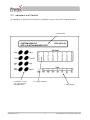
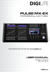
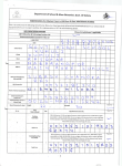
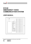
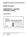
DIGILITE DL500
EMERGENCY LIGHTING
CONTROL PANEL
USER MANUAL
Protec Fire Detection PLC, Protec House, Churchill Way, Nelson, Lancashire, BB9 6RT.
Telephone:
Fax:
Web:
Email:
+44 (0) 1282 717171
+44 (0) 1282 717273
www.protec.co.uk
[email protected]
Document Revision Details
Issue
0
N93-560-84 Issue 0
Modification Detail
Document Creation
2
Author
Date
jlh
18/06/08
© Copyright Protec Fire Detection PLC 2008
Table of Contents
1.0 INTRODUCTION ............................................................................................................................. 4
2.0 INDICATIONS AND CONTROLS ................................................................................................... 5
2.1 NORMAL OPERATION ........................................................................................................................ 6
2.2 TESTING .......................................................................................................................................... 6
2.3 VIEWING EVENTS ............................................................................................................................. 6
2.4 PRINTING FAULTS AND EVENTS ......................................................................................................... 6
3.0
ACCESS LEVELS.......................................................................................................................... 7
3.1 GENERAL USER FUNCTIONS ............................................................................................................. 7
3.2 AUTHORISED USER MENU................................................................................................................. 7
3.2.1 CLEAR LATCHED EVENTS .................................................................................................................. 8
3.2.2 SET PANEL DATE/TIME ....................................................................................................................... 8
3.2.3 START MANUAL TEST ......................................................................................................................... 8
3.2.4 ABORT A TEST ..................................................................................................................................... 9
3.2.5 EDIT DEVICE TEXT .............................................................................................................................. 9
3.2.6 EDIT BUZZER SETTINGS .................................................................................................................... 9
3.2.7 SET DAILY TESTING TIME ................................................................................................................ 10
3.2.8 SET DURATION TEST MONTH .......................................................................................................... 10
4.0 FAULT EVENTS ........................................................................................................................... 11
N93-560-84 Issue 0
3
© Copyright Protec Fire Detection PLC 2008
1.0 Introduction
®
The Protec Digilite - DL500 Emergency Lighting Control Panel is designed and manufactured in the
United Kingdom and complies fully with current British Standard for the monitoring and testing of
emergency lighting units (EN 50172:2004 including BS 5266-8:2004)*.
Each panel can address up to 500 emergency lighting luminaires divided into up to 24 groups for testing
purposes, one group being tested on the corresponding day of the month. During normal operation, the
panel monitors each light unit, confirming its loop connection and if the batteries are charging. Up to 32
panels can be interconnected to allow a total capacity for testing 8160 luminaires with control and
reporting from a single central master panel.
Automatic testing is carried out to European and British Standard.
[1] MONTHLY The mains supply to each luminaire is failed for a period sufficient to ensure that each lamp
is illuminated.
[2] YEARLY The mains supply to each luminaire is failed for the full rated duration of 3 hours, during
which time the light output from each unit is monitored. Following the test, the unit is checked to ensure
that normal supply has been restored.
In addition to automatic testing, groups of lighting units can be programmed to test at any time. The test
period can be set for any time up to a maximum of 180 minutes. The panel will not allow units to be tested
if the batteries are not fully charged.
Maintained luminaires are monitored to ensure that the lamp is lit.
The system is programmable for use with Central Battery and Static Inverter Systems.
As the integrity and reliability of any system is vital the DL500 monitors critical paths for faults.
Therefore, the interface wiring is constantly monitored and the internal power supply regularly
performs self-checks to ensuring it is in full working order and that the stand-by batteries are good.
Any faults detected are reported on the front panel display and logged, a fault output is provided for
connection to external systems to signal that the DL500 has a fault and attention is required.
*When used with the handheld printer or PC.
Important Note:
There are no user serviceable parts inside the DL500 panel. Any internal maintenance work
MUST be carried out by a competent person trained to undertake such work. A separate
installation, commissioning and maintenance manual is available.
This product has been manufactured in conformance to the requirements of all applicable EU council
directives.
N93-560-84 Issue 0
4
© Copyright Protec Fire Detection PLC 2008
2.0 Indications and Controls
The DL500 has a comprehensive front panel, enabling the system status to be readily determined.
LCD Indicator
SYSTEM HEALTHY
SITE LOCATION BANNER TEXT
Push buttons used for
code entry, lamp test
and programming
N93-560-84 Issue 0
17/01/08 10:30
Test Group Indications
Fault Indications
5
© Copyright Protec Fire Detection PLC 2008
2.1 Normal Operation
The panel will normally be showing:-
SYSTEM HEALTHY
DD/MM/YY hh:mm
Site Location Banner Text
The banner text is programmed during the commissioning phase and cannot be changed by the user.
2.2 Testing
During a test the relevant Test Group LED will be flashing.
2.3 Viewing Events
The General Fault illuminates and the buzzer sounds for any fault or test failure.
Faults are indicated by flashing LEDs on the front panel and described on the 2-line display.
Test failed events are indicated by the Test Failed LED flashing and latch until cleared manually (See
Section 3.2.1).
The buzzer is muted by pressing the Mute Buzzer button, which also steadies any flashing indications.
The display shows these as below: -
EVENT 001/005 DEVICE FAIL TEST (BATT)
Location Text Up To 40 Characters as required
The Up and Down buttons scroll through date and time of the event:
dd/mm/yy HH:MM
And detailed engineer information:
LOOP 1 ADDRESS 001 GROUP 24
8 Watt
The Next and Previous buttons show the next and previous events with the second line remaining as
setwith the Up and Down buttons.
15 seconds after the last button pressed the display reverts to Event 001 and the location text
2.4 Printing Faults and Events
Not available with this version.
N93-560-84 Issue 0
6
© Copyright Protec Fire Detection PLC 2008
3.0
Access Levels
The DL500 has two access levels for users: -
3.1 General User Functions
Access level 1 allows the general user to view the system status at any time.
The following functions may be performed: •
•
•
Muting the internal buzzer
Lamp Test
Entering the code for access to the Authorised User Menu
To mute the buzzer or perform a lamp test press the respective button.
To gain access to the Authorised User Menu press ‘Select’ :SW VERSION
V1.01
PLEASE ENTER CODE
CODE ENTRY :
:0
Enter the security code 4 2 2 1, using the right hand column of buttons as digits (1) to (4).
th
Incorrect entries will clear to 0 after 5 digit or press ‘Escape’ to start again.
3.2 Authorised User Menu
After entering the last digit of the code the display shows: SELECT OPTION: CLEAR LATCHED EVENTS
If no button is pressed within 10 seconds the system reverts to General User mode, after a button
press this timeout becomes 4 minutes. This is a protection mechanism in case the system is left in
Authorised User mode.
The Authorised User level allows access to various system functions.
Pressing ‘Next’ displays the following options
•
•
•
•
•
•
•
•
SET PANEL DATE/TIME
START MANUAL TEST
ABORT A TEST
EDIT DEVICE TEXT
EDIT BUZZER SETTINGS
SET DAILY TESTING TIME
SET DURATION TEST MONTH
CLEAR LATCHED EVENTS
Pressing ‘Previous’ cycles back through the list.
Pressing ‘Escape’ returns to General User mode.
N93-560-84 Issue 0
7
© Copyright Protec Fire Detection PLC 2008
3.2.1 CLEAR LATCHED EVENTS
‘Test Failed’ events are latching events and will continue to be displayed until manually cleared.
This is achieved using this menu option
CLEAR LATCHED EVENTS :NO
Pressing Next or Previous toggles between YES and NO.
Display YES and press Select to clear any latched events.
The system returns to the Select Option menu.
3.2.2 SET PANEL DATE/TIME
When this option is selected, the date and time are displayed as below.
DD/MM/YY hh:mm
The Up & Down buttons change the value under the flashing cursor.
Next & Previous move the flashing cursor.
Press Select when complete, or Escape to ignore changes.
3.2.3 START MANUAL TEST
A manual test can be started for any or all of the 24 groups for any period up to 180 minutes.
START MANUAL TEST :GROUP 01 FOR 002 MINUTES
The Up & Down buttons change the value under the flashing cursor.
Down from Group 1 or Up from Group 24 allows All Groups to be tested
Next & Previous move the flashing cursor between Group and Minutes.
Press Select to start the test, or Escape to quit.
The relevant Test Group Led will flash for the duration of the test.
See Section 3.2.7 for suggestions about testing times.
N93-560-84 Issue 0
8
© Copyright Protec Fire Detection PLC 2008
3.2.4 ABORT A TEST
Any currently active test can be aborted
ABORT A TEST :GROUP 01
The Up & Down buttons change the group number.
Press Select to abort the test, or Escape to quit.
3.2.5 EDIT DEVICE TEXT
LOADING DATA FROM MEMORY PLEASE WAIT
Followed by
EDIT DEVICE TEXT :- LOOP 1, ADDRESS 001
Device text if already programmed
Next & Previous move the flashing cursor firstly through Loop and Address then through the 40
character text space.
Up and down select the value under the flashing cursor.
Pressing select in the text area increments to the next address.
Press Escape when finished and answer the question :SAVE ALL CHANGES MADE ?
YES – PRESS SELECT TO SAVE CHANGES
Pressing Select save the changes to memory.
Pressing Next, Previous, Up or Down shows :NO – PRESS SELECT TO DISCARD CHANGES
Pressing Select leaves the memory contents unchanged.
3.2.6 EDIT BUZZER SETTINGS
BUZZER SETTINGS :BUZZER ENABLED : NO
Pressing Next or Previous changes Yes to know and No to Yes.
Press Select when the desired option is displayed
N93-560-84 Issue 0
9
© Copyright Protec Fire Detection PLC 2008
3.2.7 SET DAILY TESTING TIME
Automatic tests occur each day for the 24 groups on the corresponding day of the month. The time of
the test is set up to suite the working or occupation conditions for the building. Because of the annual
test, it is advisable to set the testing in the morning so the system can recharge during daylight hours
and thus have some standby capacity. In areas without natural light set the test time to coincide with
unoccupied periods.
SET DAILY TESTING TIME :hh:mm Hrs
Pressing Next or Previous moves the flashing cursor between Hours (hh) and Minutes (mm).
Up and Down change the value under the flashing cursor.
Note the use of the 24 Hour clock
3.2.8 SET DURATION TEST MONTH
The is usually set to the month of commissioning so that 12 months later the system is tested for the
full duration.
SET DURATION TEST MONTH
01
Pressing Up or Down changes the number of the Month.
Press Select to save the value of Escape to leave unchanged.
N93-560-84 Issue 0
10
© Copyright Protec Fire Detection PLC 2008
4.0 Fault Events
DEVICE MISSING
A device at the address and in the group shown is no longer being ‘seen’ on the system
DEVICE MEM FAULT,
A device at the address and in the group shown has failed it’s own internal memory check.
BATTERY CHARGE FAULT
A device at the address and in the group shown is no longer charging the battery.
DEVICE LAMP FAULT
A power flood device at the address and in the group shown cannot detect the lamps.
DEVICE LOCAL MAINS FAULT
A local mains failure unit at the address and in the group shown has detected a mains failure.
DEVICE FUSE FAILURE
A fuse failure monitor unit at the address and in the group shown has detected a fuse failure.
DEVICE FAIL TEST (BATT)
A device at the address and in the group shown has failed to maintain light output for the required
time. This is a latching fault and can only be cleared from the user menu (See 3.2.1).
DEVICE FAIL TEST (LAMP),
A device at the address and in the group shown has failed to light the lamp. This is a latching fault and
can only be cleared from the user menu (See 3.2.1).
LOOP OPEN CIRCUIT
A break in the loop wiring has been detected by the panel.
LOOP OVERLOAD
Excessive current has been detected on the loop. Usually indicates a short circuit.
LOOP WIRING FAULT
A condition between open and short circuit has been detected.
PRINTER FAULT
The printer is out of paper or not present when the print command is used.
REPEAT PANEL FAULT,
A repeat panel has a fault or is no longer ‘seen’ by the panel.
HW CHECKSUM FAULT,
Panel internal program checks have detected a failure.
BUZZER DISABLED,
The panel buzzer has been disabled from the user menu (See 3.2.6).
PSU BATTERY FAULT,
The panel battery is not charging or disconnected.
PSU COMMS FAULT
The panel power supply is not communicating with the panel.
PSU BATTERY UNDER VOLTAGE
The battery voltage is low.
N93-560-84 Issue 0
11
© Copyright Protec Fire Detection PLC 2008
PSU BATTERY OVER VOLTAGE
The battery voltage is high.
MAINS FAILURE
The mains supply to the panel has failed and the system is running on batteries.
INTERFACE COMMS LINK FAIL
The link to the TCP/IP interface has failed.
INTERFACE ROM CHECKSUM FAIL
TCP/IP interface internal program checks have detected a failure.
FUNCTIONAL TEST PENDING
A functional test on the indicated group is overdue because the batteries are not sufficiently charged
for the test.
DURATION TEST PENDING
A duration test on the indicated group is overdue because the batteries are not fully charged for the
full duration test.
N93-560-84 Issue 0
12
© Copyright Protec Fire Detection PLC 2008