1
2N®
SmartGate UMTS
UMTS + GSM gateway
User guide
Version
1.1.0
www.2n.cz
The 2N TELEKOMUNIKACE a.s. joint-stock company is a Czech manufacturer and supplier
of telecommunications equipment.
The product family developed by 2N TELEKOMUNIKACE a.s. includes UMTS/GSM
gateways, private branch exchanges (PBX), and door and lift communicators. 2N
TELEKOMUNIKACE a.s. has been ranked among the Czech top companies for years and
represented a symbol of stability and prosperity on the telecommunications market for
almost two decades. At present, we export our products into over 120 countries
worldwide and have exclusive distributors on all continents.
2N® is a registered trademark of 2N TELEKOMUNIKACE a.s.. Any product and/or other
names mentioned herein are registered trademarks and/or trademarks or brands
protected by law.
2N TELEKOMUNIKACE administers the FAQ database to help you quickly find information
and to answer your questions about 2N products and services. On faq.2n.cz you can find
information regarding products adjustment and instructions for optimum use and
procedures „What to do if...“.
Declaration of Conformity
2N TELEKOMUNIKACE a.s. hereby declares that the 2N® EasyRoute product complies
with all basic requirements and other relevant provisions of the 1999/5/EC directive. For
the full wording of the Declaration of Conformity see the CD-ROM enclosed and at www.2n.cz.
2N TELEKOMUNIKACE is the holder of the ISO 9001:2000 certificate. All development,
production and distribution processes of the company are managed by this standard and
guarantee a high quality, technical level and professional aspect of all our products.
Table of Contents
1. Product Overview ............................................................. 7
1.1
Product Description ................................................................................................... 8
Basic Features ............................................................................................................. 8
Advantages of 2N® SmartGate UMTS use ................................................................... 8
Safety Precautions ....................................................................................................... 9
1.2
Changes ................................................................................................................... 10
1.3
Terms and Symbols Used........................................................................................ 11
Manual Symbols ........................................................................................................ 11
Future functions ......................................................................................................... 11
2. Description and Installation ........................................... 13
2.1
Description ............................................................................................................... 14
Telephone Line Tones – Operational Tones ............................................................... 15
Telephone Line Tones – Programming Mode ............................................................. 16
2.2
Before You Start....................................................................................................... 17
Product Completeness Check .................................................................................... 17
Installation requirements ............................................................................................ 17
2.3
Mounting .................................................................................................................. 19
External Antenna Connection ..................................................................................... 19
SIM Card Installation .................................................................................................. 19
Power Supply Connection .......................................................................................... 19
2.4
Telephone line connection ...................................................................................... 21
DialThru gateway – basic connection ......................................................................... 21
Gateway for extension line of PBX ............................................................................. 21
Gateway for trunk line of PBX..................................................................................... 21
Gateway for both, trunk and extension, lines of PBX................................................... 21
2.5
SMS Sending Input Connection .............................................................................. 22
3. Configuration 2N® SmartGate UMTS ............................ 23
3.1
2N® SmartGate UMTS parameters configuration .................................................... 24
PC Connection........................................................................................................... 24
2N® SmartGate UMTS Parameter Programming ........................................................ 24
Telephone Line based Programming .......................................................................... 24
PC based Programming ............................................................................................. 25
Further Data Handling Options ................................................................................... 26
Monitoring .................................................................................................................. 28
Firmware Upgrade ..................................................................................................... 28
3.2
Table of Parameters ................................................................................................. 30
Telephone interface FXS parameters ......................................................................... 30
Telephone interface FXO parameters......................................................................... 35
FXS routing table parameters..................................................................................... 38
FXO routing table parameters .................................................................................... 41
UMTS/GSM routing table ........................................................................................... 44
SMS Sending Input Parameters ................................................................................. 47
GSM & SIM Parameters ............................................................................................. 47
Service Parameters.................................................................................................... 49
Initialization ................................................................................................................ 50
Security Parameters................................................................................................... 51
4. Function and Use ........................................................... 53
4.1
Voice function .......................................................................................................... 54
DialThru gateway ....................................................................................................... 54
Gateway for extension line of PBX ............................................................................. 55
Gateway for trunk line of PBX..................................................................................... 56
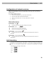
Configuration of network services............................................................................... 58
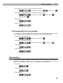
Call forwarding ........................................................................................................... 58
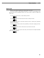
Call waiting ................................................................................................................ 60
Call hold..................................................................................................................... 61
4.2
SMS Sending Input .................................................................................................. 62
4.3
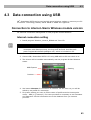
Data connection using USB..................................................................................... 63
Connection to internet–Sierra Wireless module version .............................................. 63
Connection to internet – Simcom module version ....................................................... 64
4.4
SIM Card PIN protection .......................................................................................... 66
PIN Entering by PCManager ...................................................................................... 66
PIN Entering via Telephone Line ................................................................................ 66
Automatic PIN Entering .............................................................................................. 67
5. Technical parameters..................................................... 69
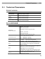
5.1
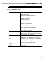
Technical Parameters .............................................................................................. 70
Product versions ........................................................................................................ 70
Sierra UMTS/GSM ..................................................................................................... 70
Simcom UMTS/GSM .................................................................................................. 71
Power Supply............................................................................................................. 72
Battery backup (optional) ........................................................................................... 72
Telephone Interface FXS (for PBX external line or phone set) .................................... 72
Telephone Interface FXO (for PBX extension line)...................................................... 73
Dial thru parameters................................................................................................... 73
SMS Sending Input .................................................................................................... 73
Data Interface ............................................................................................................ 73
Others........................................................................................................................ 74
6. Supplementary Information ........................................... 75
6.1
Regulations and directives ...................................................................................... 76
6.2
Troubleshooting....................................................................................................... 77
6.3
List of Abbreviations................................................................................................ 79
6.4
General Instructions and Cautions ......................................................................... 81
Electric Waste and Used Battery Pack Handling......................................................... 82
1
1.
Product
Overview
In this section, we introduce the 2N® SmartGate UMTS product, outline its
application options and highlight the advantages following from its use. This chapter
also includes safety instructions.
Here is what you can find in this section:
n
Product Description
n
Manual changes description
n
Abbreviations, Terms and Pictograms Used.
7
Product Description
1.1
1.1 Product Description
Basic Features
n
The primary purpose of 2N® SmartGate UMTS is to transmit voice between
UMTS/GSM network and attached phone terminals. You can connect terminal
with FXO interface (trunk line of PBX, phone set, answering machine etc.) to
FXS interface on 2N® SmartGate UMTS (connector with phone icon) and
terminal with FXS interface (extension line of PBX) to FXO interface on 2N®
SmartGate UMTS (connector with crossed out phone icon).
n
You can establish data connections (HSPA, UMTS, EDGE, GPRS, CSD) and
send/receive SMS using 2N® SmartGate UMTS in combination with a PC and
appropriate software.
n
You can send an SMS to a pre-programmed number using the SMS sending
input.
n
Version of SmartGate UMTS with Battery backup allows the function in case of
power failure.
Advantages of 2N® SmartGate UMTS use
n
Call cost cutting – the calls are routed to UMTS/GSM or analog network
according to their number prefix. Route all UMTS/GSM calls from PBX to 2N®
SmartGate UMTS to save a lot on PSTN – UMTS/GSM calls.
n
Easy installation – you can easy program 2N® SmartGate UMTS as you
need with enclosed SW.
n
You get all you need in the delivery – your 2N® SmartGate UMTS delivery
contains all you need to operate the system (the power supply adapter,
telephone cables, PC serial cable, SMS input connector, CD-ROM with
software).
n
Solution for sites without telephone lines – such as mountain chalets,
exhibitions, conferences, etc.
n
DialThru technology – all your calls will be routed most cost-effective way.
n
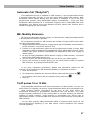
ME – Mobility Extension – you newer miss an incoming call from analog
network. Incoming call will ring on connected phone and on your mobile
phone too.
n
CLIP - 2N® SmartGate UMTS is equipped with the FSK-based CLIP feature,
so if a terminal capable of receiving the CLIP is used you know the caller‘s
number.
n
SMS sending input – simply send an SMS to a pre-programmed number by
closing the contact. Recommended for easy supervision, simple securing, etc.
n
Radiation hazard minimization – you are not exposed to a direct effect of
the antenna RF electromagnetic field while telephoning as opposed to mobile
telephones.
8
Product Description
1.1
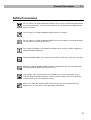
Safety Precautions
Do not switch on 2N® SmartGate UMTS in the vicinity of medical apparatuses
to avoid interference. The minimum distance of the antenna and pacemakers
should be 0.5m.
Do not switch on 2N® SmartGate UMTS aboard of a plane.
Do not switch on 2N® SmartGate UMTS near petrol stations, chemical facilities
or sites where explosives are used.
Any mobile telephone use prohibition based on RF energy radiation applies to
2N® SmartGate UMTS too.
2N® SmartGate UMTS may disturb the function of TV sets, radio sets and PCs.
Warning! 2N® SmartGate UMTS contains components that can be swallowed
by small children (SIM card, antenna, etc.).
The voltage value mentioned on the adapter may not be exceeded. If you
connect 2N® SmartGate UMTS to another power supply, make sure that the
voltage value is in the acceptable range.
When your 2N® SmartGate UMTS comes to the end of its operational life,
dispose of it in accordance with applicable regulations.
9
Changes
1.2
1.2 Changes
Manual
Version
Amendments to Earlier Versions
1.0.0
The User Manual for SmartGate UMTS.
1.0.1
Corrected errors in text
1.0.2
US version included
1.1.0
Version with module SIM5320 added
Caution
n
n
The manufacturer continuously meets customer requirements by
improving the firmware. For the latest 2N® SmartGate UMTS processor
firmware, programming tool and User Manual see www.2n.cz.
For a detailed description of the 2N® SmartGate UMTS firmware upgrade
refer to the section devoted to the PC programming tool.
10
Terms and Symbols Used
1.3
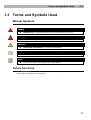
1.3 Terms and Symbols Used
Manual Symbols
Safety
n
Always abide by this information to prevent persons from injury.
Warning
n
Always abide by this information to prevent damage to the device.
Caution
n
Important information for system functionality.
Tip
n
Useful information for quick and efficient functionality.
Note
n
Routines or advice for efficient use of the device.
Future functions
Grey marked text in this document specifies functions of 2N® SmartGate UMTS ,
which will be supported in the future.
11
2
2.
Description and
Installation
This section describes the2N® SmartGate UMTS product and its installation.
Here is what you can find in this section:
n
Product Description
n
Before You Start
n
Mounting
n
Telephone line connection
n
SMS Sending Input connection
13
Description
2.1
2.1 Description
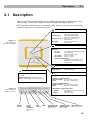
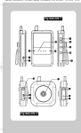
Packing of 2N® SmartGate UMTS contains UMTS/GSM gateway in white plastic cover,
power supply, antenna and cables for connecting phone interfaces and PC
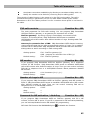
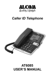
2N® SmartGate UMTS’s status is indicated by LED diodes on its front side. All possible
states are described in the following figure.
Power supply
Light blue
2N® SmartGate UMTS is
powered from the grid.
Light yellow
2N® SmartGate UMTS is
powered from the battery.
Flashes 1x in 2s HW error, contact the
manufacturer
No light
HW error, contact the
manufacturer
Figure 2.1
2N® SmartGate
UMTS LED indicators
UMTS/GSM network
Light blue
Flashes:
1x in 1s
1x in 3s
Registered to UMTS/GSM
not registered, SIM card inserted
not registered,
SIM card not inserted
4x quickly
enter your PIN
8x quickly
enter your PUK
Quickly continuously
All functions are blocked. Your
SIM doesn’t correspond to the
operator lock.
Data
Signal strength/baterry indicator
device connected to PC
No light
Light yellow
no data transmission
data transmission
Telephone line
Steady state – signalization of signal
strenght
No light
FXS line off hook – signalization of
battery state (battery backup type only)
Standby
Orange for FXS interface:
Flashes quickly line off-hook or ringing
Light
call FXS - UMTS/GSM
Green for FXO interface:
Flashes quickly line off-hook or ringing
Light
call FXO - UMTS/GSM
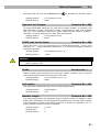
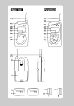
Figure 2.2
2N® SmartGate
UMTS Connectors
Alternately oragne and green:
Quickly
ringing from FXO is connected to
FXS interface
Slowly
call FXS - FXO
Switch
ON/OFF
Power
supply
connector
(DC Jack 2.1
mm)
USB
(USB B)
SIM
Telephone line
FXS interface
(RJ 12, 6/2)
Telephone line
FXO interface
(RJ 12, 6/2)
SMS connector
SMS sending input
14
Description
2.1
Telephone Line Tones – Operational Tones
The UMTS/GSM gateway sends tones to the telephone line to indicate the line status.
The tone frequency is 425 Hz in initial setting. Frequency is programmable; it is
possible to set up double frequency tones.
Dial tone
n
continuous or morse A
n
2N® SmartGate UMTS is ready to receive dialing.
Ringing tone
n
Only
n
The called subscriber's telephone is ringing.
n
The UMTS/GSM network or connected PBX transmits this tone. For connection
to UMTS/GSM network is possible to generate this tone in Gateway according
to setting. This tone is generated till the UMTS/GSM network starts to
transmit Ringback tone.
Busy tone
n
, programmable cadency
In case of call routing to UMTS/GSM network 2N® SmartGate UMTS generate busy
tone in any of the following cases:
n
The SIM card has not been installed.
n
2N® SmartGate UMTS is not registered to UMTS/GSM network.
n
2N® SmartGate UMTS is registered into a foreign network but roaming is
disabled.
n
The called subscriber line is busy.
n
The called subscriber hangs up (disconnection).
n
The called number has too many digits (more than 30).
n
The called number is barred.
In case of call routing to SmartGate UMTS’s FXO interface 2N® SmartGate UMTS
generate busy tone in any of the following cases:
n
Line is not connected. There is no current on the line.
n
The called number has too many digits (more than 30).
n
The called number is barred.
n
If the called subscriber line is busy or called subscriber hangs up, busy tone is
generated by PBX.
15
Description
2.1
Dialing end signaling
n
Only
n
Dialing reception has been terminated. Connection is being established.
PIN tone
n
n
Enter the PIN code.
n
This tone is transmitted upon power up if the PIN has to be entered manually.
PUK tone
n
Enter the PUK code.
n
n
This tone is transmitted upon repeated wrong PIN entering attempts. SIM
card is blocked.
Telephone Line Tones – Programming Mode
Tones confirming/refusing the values entered are transmitted during telephone line
based programming. Each tone has a different melody.
Confirmation
n
n
Confirms that the service password or parameter number entered is correct
and has been accepted.
Refusal
n
n
Incorrect parameter number;
n
Incorrect parameter value
n
Transmitted when a parameter is cancelled with a
.
Saving
n
n
Parameter value entered is correct and has been saved
16
Before You Start
2.2
2.2 Before You Start
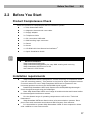
Product Completeness Check
Check the product for completeness before installation please:
n
1× 2N® SmartGate UMTS
n
1× Magnetic Antenna with coax cable
n
1× Supply adapter
n
2× Telephone Cable
n
1× PC-connection USB cable
n
1× SMS sending input connector
n
2× Dowel
n
2× Screw
n
1× CD-ROM with User Manual and software1)
n
1× Quick Installation Guide
Note
n
1)
Enclosed software:
2N® SmartGate PCManager
2N® SmartGate SMS gateway for easy SMS sending and receiving
2N® SmartGate UMTS Driver for PC
User Manual in PDF format
Installation requirements
n
2N® SmartGate UMTS is designed for vertical mounting on suspension holes
(use the mounting pattern). This position is the best for signal reception because
a vertical antenna is used. 2N® SmartGate UMTS can be operated in the
horizontal position too where the UMTS/GSM signal is good.
n
Install 2N® SmartGate UMTS with respect to the UMTS/GSM signal strength –
check the signal strength using the PCManager.
n
Place 2N® SmartGate UMTS out of range of sensitive devices and human bodies
for electromagnetic interference reasons.
n
For the allowed range of operating temperatures refer to the “Technical
Parameters”.
n
2N® SmartGate UMTS can disturb other telecommunication systems. Place
phone lines and connected terminals and PBX’s faraway from antenna.
n
It is impossible to operate 2N® SmartGate UMTS on sites exposed to direct
solar radiation or near heat sources.
17
Before You Start
2.2
n
2N® SmartGate UMTS is designed for indoor use. It may not be exposed to
rain, flowing water, condensed moisture, fog, etc.
n
2N® SmartGate UMTS may not be exposed to aggressive gas, acid vapours,
solvents, etc.
n
2N® SmartGate UMTS is not designed for environments with high vibrations
such as means of transport, machine rooms, etc
Caution
n
Check that you have everything needed for 2N® SmartGate UMTS startup (SIM card, analogue phone set or FXO port of PBX, eventually PC etc.)
18
Mounting
2.3
2.3 Mounting
External Antenna Connection
Screw the antenna cable into the SMA antenna connector.
Caution
n
Tighten the antenna connector gently with your hand – never use
wrenches!
Note
n
For the best signal level fix the antenna in vertical position.
n
Use signal strength indicator to find best place for antenna.
SIM Card Installation
Slot for SIM card is placed on the connector panel. Insert the SIM card to the slot with
contacts oriented to the front panel. Make sure that the card is locked properly.
Cautions
n
Make sure that the UMTS/GSM provider’s SIM card is compatible with the
UMTS/GSM network supported by your 2N® SmartGate UMTS version.
n
Select the required UMTS/GSM provider and SIM card services, such as
call forwarding, call barring, preferred networks, SMS service centre, etc.
in your mobile phone before inserting your SIM card in
2N® SmartGate UMTS.
Power Supply Connection
2N® SmartGate UMTS is fed with 10-16V DC. Where a source other than the included
power supply adapter is used, the voltage range and polarity have to be maintained. See
technical parameters.
2N® SmartGate UMTS with battery option allows to support functionality in case of
power failure. For backup use four pieces of accumulators NiMh size AA. These
accumulators are not part of delivery. Put the accumulators to the battery holder on
the bottom side under the cover prior to installation. Polarity of accumulators is
marked inside of the battery space.
Warning
n
Do not activate the power supply until the antenna is connected to
2N® SmartGate UMTS to avoid the UMTS/GSM module damage.
19
Mounting
2.3
n
For backup use only suggested type of accumulators NiMh size AA. Only
this type of storage batteries is permitted for use!.When another type of
batteries is used, there is a danger of damage of device or even
explosion!
n
The battery should never be placed in municipal waste. Please
check local regulations for disposal of batteries.
20
Telephone line connection
2.4
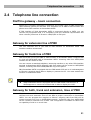
2.4 Telephone line connection
DialThru gateway – basic connection
Phone set is normally connected to extension line of PBX. Wire up 2N® SmartGate
UMTS between phone set and PBX. Link extension line of PBX to FXO interface and
phone set to FXS interface on SmartGate UMTS.
If FXO interface of 2N® SmartGate UMTS is connected directly to PSTN, you can
connect only equipment that is in compliance with the essential requirements and
other relevant provisions of Directive 1999/5/EC to FXS port.
Gateway for extension line of PBX
Link free extension line of your PBX to FXO interface on SmartGate UMTS. FXS
interface remains unconnected.
Gateway for trunk line of PBX
Link free trunk line of your PBX to FXS interface on SmartGate UMTS. Program PBX
to route all UMTS/GSM calls to SmartGate UMTS. Incoming calls from UMTS/GSM
network will be routed to PBX.
You can connect a standard telephone, answering machine or any other FXO-interface
terminal to SmartGate UMTS. Outgoing calls from phone will be routed to UMTS/GSM
network, incoming calls from UMTS/GSM will ring on the phone.
2N® SmartGate UMTS is equipped with the FSK-based CLIP and so it is advantageous
to connect a terminal that is able to display or process the CLI. You must activate the
function on SmartGate UMTS.
Tip
n
2N® SmartGate UMTS is equipped with the FSK-based CLIP and so it is
advantageous to connect a terminal that is able to display the CLIP.
Gateway for both, trunk and extension, lines of PBX
2N® SmartGate UMTS is very flexible thanks to his three routing tables. You can
connect trunk and extension lines of one PBX to proper connectors on SmartGate
UMTS. You can program the complex as follows: outgoing calls from PBX will be
routed through trunk line to UMTS/GSM network. Incoming calls from UMTS/GSM
will be routed to extension line of PBX. This configuration is suitable for PBX’s with
no capability of dial-in on trunk lines.
21
SMS Sending Input Connection
2.5
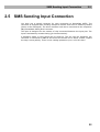
2.5 SMS Sending Input Connection
You have got a special connector for easy connection to SmartGate UMTS. The
connector is equipped with screwing clamps to connect wires from a switching contact
(device to be monitored). The other connector end can be connected to the respective
2N® SmartGate UMTS panel connector.
The input is designed for the contact of relay connected between the input pins. The
input is activated by contact closing (pin interconnection).
A transistor switch or logic signal can be used too. The pin near the telephone line
connector is connected to GND of the device the second one is active. Please, respect
the loop current polarity. There is over-voltage protection up to +12V DC there.
22
3
3.
Configuration
2N® SmartGate
UMTS
This section describes configuration of the product 2N® SmartGate UMTS.
Here is what you can find in this section:
n
PC Connection to 2N® SmartGate UMTS
n
2N® SmartGate UMTS Parameter Programming
n
Table of Parameters
7
23
2N® SmartGate UMTS parameters configuration
3.1
3.1 2N® SmartGate UMTS parameters
configuration
PC Connection
You have got a USB cable for PC connection.
Caution
n
Make sure that a longer cable works properly to avoid errors at high
transmission rates.
2N® SmartGate UMTS Parameter Programming
Most of SmartGate UMTS’s parameters have such default values that meet most users’
demands and need not be changed. Usually you have to program routing tables
according to 2N® SmartGate UMTS usage. There are two possibilities how to program
SmartGate UMTS:
n
Use phone line and DTMF programming from connected phone set. This is not
applicable for all parameters
n
Use a PC with the PCManager installed. Using this way all parameters
supported by 2N® SmartGate UMTS can be programmed.
Telephone Line based Programming
1.
2.
Hook off the telephone, you can hear the dial tone or the busy tone, and the
Line LED starts flashing.
Enter the service password (12345 by default, can be changed) with the
DTMF; to cancel a wrong password hang up before sending the
To confirm password enter a
3.
character.
.
If you have entered a correct password, you hear the confirmation tone. If
not, the dialed number may be sent to the UMTS/GSM network as a call. To
prevent this, hang up when you do not hear the confirmation tone.
4.
2N® SmartGate UMTS shall remain in the programming mode until hang-up.
5.
Enter the number of the parameter to be programmed and press a
. If the
parameter number is correct, you can hear the confirmation tone, if not, you
get the refusal tone and can re-enter the parameter number.
6.
When the parameter number is confirmed, enter the allowed parameter value
. If the parameter value is in the allowed range, you can hear
and press a
the saving tone, if not, you get the refusal tone. You can enter another
parameter number in either case.
24
2N® SmartGate UMTS parameters configuration
3.1
Numeric parameters are programmed using numbers in units included in the
parameter description. The step for setting must be respected. For parameters with
different setting are values defined in the parameters description (in parenthesis).
To cancel any programming step in the programming mode, press a
. Having done
so, you can hear the refusal tone and can enter a new parameter number. Parameters
are saved when the saving tone is transmitted. Hang up to quit programming.
During phone line programming mode is the LED ‘UMTS/GSM Network’ showing the
signal strenght
Example:
Dial
Confirma on
Descrip on
Password entering, OK
Transmission volume parameter, OK
Set to medium level, saved
Non-existent parameter number, refusal
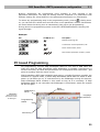
PC based Programming
For programming, connect 2N® SmartGate UMTS to a PC with a USB cable and
make sure that the 2N® SmartGate UMTS PCManager is installed. Programming is
intuitive and easy. All items and parameters are accompanied with texts hints - just
point at anything with the mouse cursor.
2N® SmartGate UMTS data uploading and storing, including firmware upgrade, are
executed in a special mode, in which 2N® SmartGate UMTS waits for about 3s after
power up (all LEDs are on). If instructed so by the PCManager during this timeout,
2N® SmartGate UMTS remains in this mode as long as it is necessary. If 2N®
SmartGate UMTS is not reset after the PCManager is terminated, switch the system
off and on again.
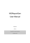
Figure 3.1
Basic screen of
SmartGate UMTS
PC Manager+
PCManager+
setup
Data
handling
Language
selection
Programming
tables
Monitoring
25
2N® SmartGate UMTS parameters configuration
3.1
Installation and setting of SmartGate PCManager (Win7)
1. Connect 2N® SmartGate UMTS to the PC using USB connection. SmartGate
must be switched off.
2. After connecting is the virtual serial port in PC installed automatically. I case,
that the port doesn’t install automatically and unknown device is detected,
install drivers by using file: Drivers/win/CDM20814_Setup.exe.
3. Find the number of virtual port using Device manager. Look at setting of COM
ports and find port marked as USB Serial Port(COMn).
4. Install PCManagerSmG from CD.
5. Run SmartGate PCManager, select the language on the upper bar.
6. In menu Program select Setup. Set the COM port – local and select COM port
number according information from point 3.
Using of PCManager - basic
1. The main purpose of PCManager is setting of configuration and upgrade
firmware of SmartGate.
2. When the configuration in SmartGate should be changed, the configuration
must be first loaded from SmartGate, than edited using PCManager and finaly
loaded back to SmartGate.
3. The groups of parameters are listed is in the left window of the program. All
parameters are described in next part of this manual. There is interactive help
in PCManager for all parameters.
4. When you start with any operation which needs communication with
SmartGate, the gateway must be switched to special programming mode.
PCManager will show you the demand to switch the gateway off and on to set it
to this mode.
Further Data Handling Options
In addition to the 2N® SmartGate UMTS memory, settings can be saved in a PC file
and reloaded into the PCManager. This is recommended for backing up of current
configuration
Caution
n
The table Security includes the PIN code and service password. These
parameters have a special handling. They are not saved in a PC file for
security reasons. If you load a PC file into the PCManager and then into
SmartGate UMTS, the PIN and service password should not change unless
you change them manually before saving.
26
2N® SmartGate UMTS parameters configuration
3.1
Caution
n
All tables are filled-in with default values after PCManager start. It is
recommended to load data from 2N® SmartGate UMTS before parameters
programming and saving. If you only save data after PCManager start, all
parameters except the PIN and service password in the 2N® SmartGate
UMTS memory will have default values.
Caution
n
The PIN and service password can only be modified either manually or by
full initialization.
27
2N® SmartGate UMTS parameters configuration
3.1
Monitoring
Monitoring is active when 2N® SmartGate UMTS is in operation and registered to
the UMTS/GSM network. If 2N® SmartGate UMTS is not registered to UMTS/GSM,
the USB port is blocked and no monitoring can be made.
This simple informative function helps you identify:
The UMTS/GSM module type and IMEI ID;
n
n
The SIM card IMSI ID and selected SMS service centre necessary for SMS
sending;
n
The UMTS/GSM provider's name and signal strength received by 2N®
SmartGate UMTS - this information helps you find the optimum signal location
(the information is updated in 10s intervals);
n
The 2N® SmartGate UMTS line status – standby, outgoing call, incoming call
including telephone number. The COM is locked during dialing and incoming call
ringing, so the PCManager reports COM blocking.
Firmware Upgrade
The manufacturer responds to clients' requirements with periodical firmware
updating. The current 2N® SmartGate UMTS firmware, PCManager and User
Manual are available on www.2n.cz. The latest firmware version is always included in
every new PCManager installation.
Upgrading procedure:
1. Run the PCManager, select the language for displaying texts on the right-hand
side.
2. In menu SmartGate use Upgrade. When the gateway is not in programming
mode, you will be instructed to switch the gateway on and on.
3. If there is more then one file in the PCManager directory, chose one of them.
The upgrade takes place automatically. Do not switch your PC or 2N®
SmartGate UMTS off during the process of upgrading!
Caution
n
The PCManager checks the software version in 2N® SmartGate UMTS and
the upgrade file. If the version in the file is new, everything is all right. An
identical or earlier software version is stored in 2N® SmartGate UMTS too
but the PCManager requires confirmation to be on the safe side.
28
2N® SmartGate UMTS parameters configuration
3.1
Caution
n
The manufacturer responds to clients' requirements with periodical
firmware updating. The latest 2N® SmartGate UMTS firmware, PCManager
and User Manual are available on www.2n.cz.
29
Table of Parameters
3.2
3.2 Table of Parameters
All programmable parameters are listed in this section. Each parameter is
accompanied with the unit used, function number (if avaliable) for programming via
a telephone line, description of SmartGate UMTS's behavior, setting options, setting
step and default (initialization) value.
Numeric parameters must be set in unit listed in the parameter description. For
parameters with different setting are values defined in the parameters description
(for phone line programming in parenthesis). When phone line programming is
used, character
can’t be included in the string, because it is dedicated for
confirmation of the new parameter value.
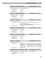
Telephone interface FXS parameters
Dialing parameters
Type of dialing
Function No.:
100
Select the dialing type to be received by 2N® SmartGate UMTS on the FXS
interface. 2N® SmartGate UMTS accepts only the selected type of dialing,
ignoring the others.
Setting options:
DTMF (0) -2N® SmartGate UMTS receives tone dialing
only.
Pulse (1) -2N® SmartGate UMTS receives pulse
dialing only
Default setting:
DTMF
Time to dial [s]
Function No.:
101
Timeout during which 2N® SmartGate UMTS waits for further digits to be dialed.
It starts to establish connection when this timeout passes.
Setting options:
Setting step:
Default setting:
1-255 s
1s
5s
Minimal On Hook [ms]
Function No.:
102
The minimum line current break that 2N® SmartGate UMTS evaluates as hangup.
Setting options:
100-25500 ms
Setting step:
Default setting:
100 ms
500 ms
Beep after dialing end
Function No.:
103
Select a beep to signal the end of dialing (beginning of outgoing call
establishing).
30
Table of Parameters
Setting options:
Default setting:
3.2
YES(1)/NO(0)
YES
Signaling
Line reversal indication for call in progress Function No.:110
Select call in progress signaling by telephone line polarity reversal on FXS
interface. There is voltage of reversed polarity on the telephone line during the
whole call.
Setting options:
YES(1)/NO(0)
Default setting:
NO
Tariff pulse when call starts/ends
Function No.:
111
Signaling of call start or end by tariff pulse.
Setting options:
None (0)-2N® SmartGate UMTS doesn't send tariff
pulse as signaling of callstart/end.
Call end (1) -2N® SmartGate UMTS sends tariff pulse
when call ends.
Call start (2)-2N® SmartGate UMTS sends tariff pulse
when call starts.
Call start and end (3) -2N® SmartGate UMTS sends
tariff pulse when call starts and ends too.
Default setting:
None
Tariff pulse frequency
Function No.:
112
Tariff pulse frequency setting.
Setting options:
16 kHz (0) -2N® SmartGate UMTS transmits 16 kHz
tariff pulses
12 kHz (1)-2N® SmartGate UMTS transmits 12 kHz
tariff pulses
Default setting:
16 kHz
Tone settings
Dial tone – Double frequency tone[Hz]
Function No.:
-
Parameter can be set for all three types of tone (Dial tone, Busy
tone,Ringbacktone). This parameter is intended for switching between single
tone and double tone setting. When the parameter is set, the second frequency
of appropriate tone must be set too. When this parameter isn’t set, the second
frequency is automatically set to the same value, which results in single tone
generation. This parameter can’t be set using phone line programming. When
the phone line programming is used for frequency change, both tones must be
set (for single frequency to the same value).
Setting options:
Default setting:
YES/NO
NO
31
Table of Parameters
Dial tone – frequency 1[Hz]
Function No.:
3.2
120
Setting of frequency 1 of dial tone. This tone is generated after Off-Hook in case
2N® SmartGate UMTS is ready to accept dialing.
Setting options:
Setting step:
efault setting:
1-3400 Hz
1 HzD
425 Hz
Dial tone – frequency 2[Hz]
Function No.:
121
Function No.:
122
Setting of frequency 2 of dial tone.
Setting options:
1-3400 Hz
Setting step:
Default setting:
1 Hz
425 Hz
Dial tone - cadence
Dial tone cadence setting.
Setting options:
Continuous ( 0) -2N® SmartGate UMTS generate
continuous dial tone
Morse A (1) -2N® SmartGate UMTS generate dial tone
with 330/330/660/660 ms timing
Default setting:
Continuous
Busy tone – frequency 1[Hz]
Function No.:
123
Function No.:
124
Function No.:
125
Setting of frequency 1 of busy tone.
Setting options:
Setting step:
Default setting:
1-3400 Hz
1 Hz
425 Hz
Busy tone – frequency 2[Hz]
Setting of frequency 2 of busy tone.
Setting options:
Setting step:
Default setting:
1-3400 Hz
1 Hz
425 Hz
Busy tone - cadence
Busy tone cadence setting.
Setting options:
330/330
200/200
250/250
375/375
500/500
Default setting:
ms
ms
ms
ms
ms
(0)
(1)
(2)
(3)
(4)
-cadence
-cadence
-cadence
-cadence
-cadence
330
200
250
375
500
ms
ms
ms
ms
ms
tone,
tone,
tone,
tone,
tone,
330
200
250
375
500
ms
ms
ms
ms
ms
pause
pause
pause
pause
pause
330/330 ms
Ring back tone – frequency 1 [Hz]
Function No.:
126
Setting of frequency 1 of ringback tone. This tone is send after dialing end,
before UMTS/GSM network starts to generate its own Ringback tone.
Setting options:
1-3400 Hz
Setting step:
1 Hz
32
Table of Parameters
Default setting:
3.2
425 Hz
Ringback tone – frequency 2 [Hz]
Function No.:
127
Setting of frequency 2 of ringback tone.
Setting options:
Setting step:
Default setting:
1-3400 Hz
1 Hz
425 Hz
Ringback tone - cadence
Function No.:
128
Ringback tone cadence setting.
Setting options:
OFF (0) -not generated, only network tone
1000/4000 ms (1) -cadence 1 s tone, 4 s pause
400/200/400/2000 ms (2) -cadence 2x400 ms tone,
2 s pause
1500/3500 ms (3) -cadence 1,5 s tone, 3,5 s pause
2000/4000 ms (4) -cadence 2 s tone, 4 s pause
Default setting:
OFF
Tone after disconnection
Function No.:
129
If the remote subscriber hangs up first, the 2N® SmartGate UMTS subscriber
can hear the tone selected here.
Setting options:
Busy (0)-2N® SmartGate UMTS transmits the busy
tone upon call end.
Permanent (1) -2N® SmartGate UMTS transmits the
permanent tone upon call end.
Default setting:
Busy tone
Volumes
Transmission volume
Function No.:
190
Volume setting for UMTS/GSM transmission with a 4 dB step.
Setting options:
Setting step:
Default setting:
1-5
1
3 = medium volume level
Reception volume
Function No.:
191
Volume setting for UMTS/GSM reception with a 4 dB step.
Setting options:
1-5
Setting step:
1
Default setting:
3 = medium volume level
Ringing signal settings
Ringing signal – frequency [Hz]
Function No.:
140
Ringing signal frequency setting.
33
Table of Parameters
3.2
Setting options:
25 / 50 Hz-2N® SmartGate UMTS rings with 50 or 25
Hz on FXS interface
Default setting:
50 Hz
Ringing signal - cadence
Function No.:
141
Ringing signal cadency setting.
Setting options:
1000/4000 ms (0) - 1 s ring, 4 s pause
400/200/400/2000 ms (1)- 400ms ring, 200ms pause,
400ms ring, 2s pause
1500/3500 ms (2) - 1,5 s ring, 3,5 s pause
2000/4000 ms (3) - 2 s ring, 4 s pause
Default setting:
1000/4000 ms
CLI transmitting
Function No.:
148
Set this item to enable/disable identification of a telephone line calling from a
UMTS/GSM network. The function can be enabled if you have a device on your
telephone line that is capable of receiving FSK according to ETSI standards.
Setting options:
Disable (0) - 2N® SmartGate UMTS does not transmit
the CLI.
FSK during ringing (1) -2N® SmartGate UMTS
transmits the FSK-based CLI according to the ETSI EN
300 659 standard (transmission during ringing).
Default setting:
Disable
Replace character + in CLI by
Function No.:
149
If this parameter is filled, the + character in the international prefix of CLI is
replaced by the defined string. The + character can neither be transmitted by
the FSK protocol nor dialed by the DTMF from a terminal.
Setting options:
0-4 characters (0-9,*,#)
Default setting:
blank
„BabyCall“ – Automatic call
BabyCall number
Function No.:
180
A number to be dialed for the automatic call function. If this item is blank, the
function is disabled.
Setting options:
Default setting:
0-20 characters (0-9,*,#,+)
blank
BabyCall timeout [s]
Function No.:
181
Time between line Off-Hook and automatic call beginning (if enabled). During
this timeout 2N® SmartGate UMTS waits for dialing that cancels the automatic
call. You can make standard call if the BabyCall function is enabled.
Setting options:
Setting step:
0-255 s
1s
Default setting:
0s
34
Table of Parameters
3.2
Telephone interface FXO parameters
Dialing parameters
Number of rings before Off-Hook
Function No.: 200
If 2N® SmartGate UMTS is programmed as FXO gateway, parameter sets the
count of rings before Off-Hook.
Setting options:
1-255
Step:
Default setting:
1
1
Timeout for dialing end recognize [s]
Function No.: 201
If 2N® SmartGate UMTS is programmed as FXO gateway, parameter defines
timeout during which 2N® SmartGate UMTS waits for further digits to be dialed.
It starts to establish connection when this timeout passes.
Setting options:
Setting step:
Default setting:
1-255 s
1s
5s
Time for dialing start
Function No.: 202
If 2N® SmartGate UMTS is programmed as FXO gateway, parameter defines
timeout for first dialing digit. After timeout 2N® SmartGate UMTS hangs up the
line.
Setting options:
Step:
Default setting:
1-255 s
1s
15 s
Beep after dialing end
Function No.: 203
If 2N® SmartGate UMTS is programmed as FXO gateway, parameter enables a
beep to signal the end of dialing (beginning of outgoing call establishing).
Setting options:
Default setting:
YES(1)/NO(0)
YES
Type of transmitted dialing
Function No.: 204
Set type of dialing for automatic dial-in from UMTS/GSM and for dialing during
outgoing call from FXS interface.
Setting options:
DTMF (0)-2N® SmartGate UMTS transmits tone dialingfor future use
Default setting:
DTMF
Minimal On-Hook [ms]
Function No.: 205
Parameter defines minimal time of line On-Hook between calls. Set the
parameter longer then duration of FLASH on your PBX.
Setting options:
100-25500 ms
Step:
Default setting:
100 ms
1500 ms
35
Table of Parameters
Maximal Off-Hook without dialing [s]
3.2
Function No.: 206
Parameter defines maximal time of line Off-Hook before dialing to FXO interface
during outgoing call from FXS interface. Set up shorter time then timeout from
extension line Off-Hook and dialing receiver disconnection on your PBX. In this
case PBX usually changes dial tone to busy tone. If defined timeout passes
before dialing, 2N® SmartGate UMTS shortly hangs up, after that Off-hooks
again and then dials.
Setting options:
Step:
Default setting:
1-255 s
1s
15 s
Signaling
Busy tone detection
Function No.: 210
Set number of busy tone periods for detection of call disconnection from your
PBX. The "0" setting disables busy tone detection.
Setting options:
Step:
0-255
1
Default setting:
4
Continuous tone detection [ms]
Function No.: -
Set duration of constant frequency continuous tone for detection of call
disconnection from your PBX. The "0" setting disables continuous tone
detection.
Setting options:
Step:
0-8900 ms
35 ms
Default setting:
2030 ms
Tone settings
Dial tone – Double frequency tone[Hz]
Function No.:
-
Parameter can be set for all three types of tone (Dial tone, Busy tone,
Ringbacktone). This parameter is intended for switching between single tone and
double tone setting. When the parameter is set, the second frequency of
appropriate tone must be set too. When this parameter isn’t set, the second
frequency is automatically set to the same value, which results in single tone
generation. This parameter can’t be set using phone line programming. When
the phone line programming is used for frequency change, both tones must be
set (for single frequency to the same value).
Setting options:
Default setting:
YES/NO
NO
Dial tone – frequency 1[Hz]
Function No.:
220
Setting of frequency 1 of dial tone. This tone is generated after Off-Hook in case
2N® SmartGate UMTS is ready to accept dialing.
36
Table of Parameters
Setting options:
Setting step:
efault setting:
3.2
1-3400 Hz
1 HzD
425 Hz
Dial tone – frequency 2[Hz]
Function No.:
221
Function No.:
222
Setting of frequency 2 of dial tone.
Setting options:
Setting step:
Default setting:
1-3400 Hz
1 Hz
425 Hz
Dial tone - cadence
Dial tone cadence setting.
Setting options:
Continuous ( 0) -2N® SmartGate UMTS generate
continuous dial tone
Morse A (1) -2N® SmartGate UMTS generate dial tone
with 330/330/660/660 ms timing
Default setting:
Continuous
Ring back tone – frequency 1 [Hz]
Function No.:
226
Setting of frequency 1 of ringback tone. This tone is send after dialing end,
before UMTS/GSM network starts to generate its own Ringback tone.
Setting options:
Setting step:
Default setting:
1-3400 Hz
1 Hz
425 Hz
Ringback tone – frequency 2 [Hz]
Function No.:
227
Setting of frequency 2 of ringback tone.
Setting options:
Setting step:
Default setting:
1-3400 Hz
1 Hz
425 Hz
Ringback tone - cadence
Function No.:
228
Ringback tone cadence setting.
Setting options:
OFF (0) -not generated, only network tone
1000/4000 ms (1) -cadence 1 s tone, 4 s pause
400/200/400/2000 ms (2) -cadence 2x400 ms tone,
2 s pause
1500/3500 ms (3) -cadence 1,5 s tone, 3,5 s pause
2000/4000 ms (4) -cadence 2 s tone, 4 s pause
Default setting:
OFF
Volumes
Transmission volume
Function No.:
190
See FXS interface parameters.
37
Table of Parameters
Reception volume
3.2
Function No.:
191
Function No.:
280
See FXS interface parameters.
„BabyCall“ – Automatic call
BabyCall number
If 2N® SmartGate UMTS is programmed as FXO gateway, parameter defines a
number to be dialed for the automatic call function. If this item is blank, the
function is disabled. If only character ‘#’ is included, after BabyCall timeout
elapsed the interfaces FXO and FXS are connected and dialing to PSTN over FXO
interface is possible.
Setting options:
Default setting:
0-20 characters (0-9,*,#,+)
blank
BabyCall timeout [s]
Function No.:
281
If 2N® SmartGate UMTS is programmed as FXO gateway, parameter defines
time between line Off-Hook and automatic call beginning (if enabled). During
this timeout 2N® SmartGate UMTS waits for dialing that cancels the automatic
call. You can make standard call if the BabyCall function is enabled.
Setting options:
0-255 s
Setting step:
Default setting:
1s
0s
Mobility extension FLASH
Mobility Extension FLASH DTMF code
Function No.: 240
Fill in DTMF code to enable GSM FLASH function. If 2N® SmartGate UMTS
receive DTMF dialing corresponding to filled code during UMTS/GSM - FXO call, it
generates FLASH to FXO interface.
Setting options:
Default setting:
0-4 characters (0-9,*,#)
blank
FLASH length [ms]
Function No.: 241
Time of current loop interruption (line On-Hook) during FLASH.
Setting options:
Step:
Default setting:
100-1500 ms
100 ms
100 ms
FXS routing table parameters
All parameters related to the dialed number and call routing are arranged in three
routing tables. Each table pertains to one interface: FXS, FXO and GSM(UMTS).
According to the prefix of dialed number on FXS interface you can:
38
Table of Parameters
3.2
n
Bar the number to be dialed - the calling subscriber
n
Route the call to UMTS/GSM network, or to PBX through the FXO interface;
n
tone;
Accelerate connection establishing by knowing the number length for the
given prefix;
n
Accelerate connection establishing by allowing to terminate dialing with a #;
n
Modify the number to be dialed by removing and/or adding prefix.
n
Set tariff metering for the given prefix
n
Set time limit for call
Every table line includes a phone number prefix (of variable length) and other
parameters. The parameters define SmartGate UMTS's behavior in case the
beginning of the dialed number matches this prefix on the same table row. The
table contains 120 rows for up to 120 different prefixes.
There may be exceptions to the rule - a number may start with the same digits but
has to be served in a different way. Any table row that starts with the same prefix
followed by one or more digits is considered an exception of the line with shorter
prefix.
Remember to complete the "Other prefixes" line for a number whose prefix is not
found in the table.
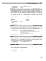
An example in the figure shows how to bar all international calls with the exception
of calls to Slovakia. Calls to Slovakia are routed through FXO interface and the call
is established immediately after 14 digits are dialed. All other calls are enabled and
they are routed to UMTS/GSM network. Their tariff is one impulse every 30 second
and you can accelerate connection establishing by dialing of a # after the dialed
number. Maximal length of the call is 10 minutes.
Operator for Integra
Function No.: 405
In some UMTS/GSM networks you can add to dialed number # character and
PBX subscriber number. Subscriber number is displayed on other side together
with CLI. This parameter take place when dialed number doesn't contain #
character. Common parameter for both FXO and FXS port.
Setting options: 0-8 characters (0-9)
Default setting: blank
39
Table of Parameters
3.2
Caution!
n
Configuration using phone line programming (DTMF) is applicable for line
‘Other prefixes’ only.
Prefix
Function No.: -
Dialed number prefix identifying the call type. "Other numbers" line is used for
calls with prefixes that are not included in the table.
Setting options:
Default setting:
0-16 characters (0-9,*,#)
blank
Call enable
Function No.:
391
This parameter allows/bars calls with corresponding prefixes.
Setting options:
Default setting:
YES(1)/NO(0)
YES
Route to
Function No.: 392
The Route to parameter defines call routing corresponding to the row.
Setting options:
GSM(0) – call is routed only to UMTS/GSM
FXO(1) - call is routed only to FXO interface
GSM, FXO(2) – call is primary routed to UMTS/GSM and
by GSM error is routed to FXO interface
FXO, GSM(3) – call is primary routed to FXO interface
and by FXO error is routed to UMTS/GSM network
Default setting:
GSM
Number length
Function No.:
393
The parameter defines the expected length of dialed number. It enables to start
dialing into UMTS/GSM or FXO interface immediately after the last digit is dialed.
If the telephone number to be dialed is shorter, a timeout is respected. The "0"
setting means that the function is disabled.
Setting options:
Setting step:
Default setting:
0, 3-15
1
0
End with #
Function No.: 394
This parameter enables to establish the call when a # is received. The #
character is removed from the dialed number. If a # should be part of the dialed
number, this function cannot be used for the given prefix.
Setting options:
Default setting:
YES(1)/NO(0)
NO
Remove
Function No.: 395
The Remove parameter is used for automatic call routing. A defined count of
digits (prefix) is removed from the number beginning.
Setting options:
Setting step:
Default setting:
0-20
1
0
40
Table of Parameters
Add
3.2
Function No.: 396
The Add parameter is used for automatic call routing. A defined string (prefix) is
added to the beginning of the number to be dialed.
Setting options:
Default setting:
0-16 characters (0-9,*,#,+)
blank
Extra tariff
Function No.: 397
Pseudo tariff metering setting (tariff is based on call duration) for UMTS/GSM
calls. Connected PBX must send tariff metering pulses for FXO calls. The Extra
tariff parameter defines transmitting of fixed quantity of tariff pulses after call
start. This parameter sets minimal call cost.
Setting options:
0-255
Setting step:
1
Default setting:
0
Tariff [s]
Function No.: 398
Pseudo tariff metering setting (tariff is based on call duration) for UMTS/GSM
calls. Connected PBX must send tariff metering pulses for FXO calls. The Tariff
parameter sets the call cost according to call duration. Set how often in seconds
do you want to transmit pulses. Smaller number means more expansive call. 0
means not to transmit pulses according to call duration.
Setting options:
Setting step:
Default setting:
0-255 s
1s
0 sFAX/DATA routing parameters
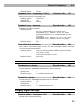
Time limit [min]
Function No.: 399
After time elapsing is call connection terminated immediately. You can hear beep
30s before end of call. 10s before end you can hear beep every second. The "0"
setting means that the function is disabled.
Setting options: 0-255 min
Setting step: 1 min
Default setting: 0 min
FXO routing table parameters
All parameters related to the dialed number and call routing are arranged in three
routing tables. Each table pertains to one interface: FXS, FXO and UMTS/GSM.
Calls from FXO interface are routed according to “FXO calls rote to” parameter. You
can set 2N® SmartGate UMTS as DialThru gateway or as gateway for extension line of
PBX.
You can program ME function for the DialThru gateway.
For gateway for extension line of PBX you can fill in the FXO routing table. According
to the prefix of dialed number on FXO interface you can:
n
Bar the number to be dialed – 2N® SmartGate UMTS hangs up, the call isn’t
established;
n
Accelerate connection establishing by knowing the number length for the
given prefix;
41
Table of Parameters
3.2
n
Accelerate connection establishing by allowing to terminate dialing with a #;
n
Modify the number to be dialed by removing and/or adding prefix.
The principle of table function is the same as in the FXS routing table. The call is
controlled according to parameters on the row with dialed number prefix match.
Remember to fill in the "Other prefixes" line for a number whose prefix is not found in
the table.
FXO calls route to
Function No.: 400
The main parameter for FXO calls routing. You can program 2N® SmartGate
UMTS as DialThru gateway, or as gateway for extension line of PBX.
DialThru gateway: Incoming ringing is immediately connected to FXS
interface. If function ME set, 2N® SmartGate UMTS starts to establish
UMTS/GSM call to ME number after defined number of rings. Routing table FXO
is not active.
Gateway for extension line of PBX: 2N® SmartGate UMTS detects incoming
ringing and Off-Hook the line after programmed number of rings, if it is possible
to make call to UMTS/GSM. 2N® SmartGate UMTS generate dial tone and after
dialing takes an action according to FXO routing table.
Setting options:
FXS - DialThru gateway (0)
GSM - gateway for extension line of PBX (1)
Default setting:
FXS - DialThru gateway
ME number
Function No.: 401
If you program 2N® SmartGate UMTS as DialThru gateway, fill in telephone
number for ME function. 2N® SmartGate UMTS starts to establish UMTS/GSM
call to ME number after defined number of rings. Then you can receive incoming
FXO call on telephone line or in UMTS/GSM network. Blank parameter disables
ME function.
Setting options:
Default setting:
0-16 characters (0-9,*,#,+)
blank
Number of rings to ME
Function No.: 402
If you program 2N® SmartGate UMTS as DialThru gateway and ME number is
filled in, 2N® SmartGate UMTS starts to establish UMTS/GSM call to ME number
after defined number of rings. Then you can receive incoming FXO call on
telephone line or in UMTS/GSM network.
Setting options:
0-255
Step:
1
Default setting:
1
Password for ME activation / disabling
Function No.: 403
If you program 2N® SmartGate UMTS as DialThru gateway and fill in ME
number, function ME is active. If you fill in password for ME activation/disabling,
you can activate/disable function ME without PC programming.
Off-Hook FXS line and dial PASSWORD plus
to disable the function.
42
Table of Parameters
Off-Hook FXS line and dial PASSWORD plus
Setting options:
Default setting:
3.2
to activate the function again.
0-8 characters (0-9)
blank
Operator for Integra
Function No.: 405
In some UMTS/GSM networks you can add to dialed number # character and
PBX subscriber number. Subscriber number is displayed on other side together
with CLI. This parameter take place when dialed number doesn't contain #
character. Common parameter for both FXO and FXS port.
Setting options:
Default setting:
0-8 characters (0-9)
blank
DTMF code for On-Hook
Function No.: 409
Using this code, you can terminate call to UMTS/GSM network, if busy tone
detection on
2N® SmartGate UMTS fails, or if connected equipment doesn't
transmit busy tone.
Setting options:
Default setting:
0-8 characters (0-9,*,#)
blank
Caution
n
Configuration using phone line programming (DTMF) is applicable for line
‘Other prefixes’ only.
Prefix
Function No.: -
Dialed number prefix identifying the call type. "Other numbers" line is used for
calls with prefixes that are not included in the table.
Setting options:
0-16 characters (0-9,*,#)
Default setting:
blank
Call enable
Function No.: 491
This parameter allows/bars calls with corresponding prefixes.
Setting options:
YES(1)/NO(0)
Default setting:
YES
Number length
Function No.: 493
The parameter defines the expected length of dialed number. It enables to start
dialing into UMTS/GSM or FXO interface immediately after the last digit is dialed.
If the telephone number to be dialed is shorter, a timeout is respected. The "0"
setting means that the function is disabled.
Setting options:
Setting step:
0, 3-15
1
Default setting:
0
43
Table of Parameters
End with #
3.2
Function No.: 494
This parameter enables to establish the call when a # is received. The #
character is removed from the dialed number. If a # should be part of the dialed
number, this function cannot be used for the given prefix.
Setting options:
YES(1)/NO(0)
Default setting:
NO
Remove
FunctionNo.: 495
The Remove parameter is used for automatic call routing. A defined count of
digits (prefix) is removed from the number beginning.
Setting options:
Setting step:
Default setting:
0-20
1
0
Add
Function No.: 496
The Add parameter is used for automatic call routing. A defined string (prefix) is
added to the beginning of the number to be dialed.
Setting options:
Default setting:
0-16 characters (0-9,*,#,+)
blank
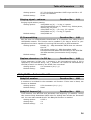
Time limit [min]
Function No.: 499
After time elapsing is call connection terminated immediately. You can hear beep
30s before end of call. 10s before end you can hear beep every second. The "0"
setting means that the function is disabled.
Setting options: 0-255 min
Setting step: 1 min
Default setting: 0 min
UMTS/GSM routing table
All parameters related to the dialed number and call routing are arranged in three
routing tables. Each table pertains to one interface: FXS, FXO and UMTS/GSM.
Incoming calls from UMTS/GSM contain the CLI. According to received CLI 2N®
SmartGate UMTS can do following:
· Reject the call;
· Route the call to FXS or FXO interface;
· Automatic dial in. 2N® SmartGate UMTS dials preprogrammed PBX subscriber
number (for example switchboard operator) to be connected with calling
UMTS/GSM subscriber.
FXS line Off-Hook to DISA timeout [ms]
Function No.: 500
Timeout between FXS line Off-Hook and automatic dial in according to parameter
"Dial in" in the table.
Setting options:
100-25500 ms
Setting step:
100 ms
Default setting:
2000 ms
44
Table of Parameters
FXO line Off-Hook to dial-in timeout [ms]
3.2
Function No.: 501
Timeout between FXS line Off-Hook and automatic dial in according to parameter
"Dial in" in the table.
Setting options:
Setting step:
Default setting:
100-25500 ms
100 ms
1000 ms
Max. ring time for CallBack
Function No.: 502
Parameter sets up a behaviour for CallBack function. You've got 2 options how to
use a Callback on the FXS port:
Simple CallBack - set up for 0. During an incoming call the FXS port gives a
ringing. When the FXS port is off-hooked an incoming call from UMTS/GSM is
rejected and after 10s the gateway calls back the UMTS/GSM number. During
those 10s the caller must hang up to be ready for answering the callback call. On
the FXS port a melody is played.
Advanced Callback - set up for 1-255. During an incoming call the FXS port gives
a ringing. If the caller wants to use a callback functionality he/she must hang up
before the parameter Max. ring time for Callback runs out. The gateway then
calls back immediately. If the call is answered on the analog side earlier the
called party hears the melody. If the call is answered on the UMTS/GSM side first
then the calling party number hears the melody. If the caller doesn't want to use
the Callback he just doesn't hang up and the call is handled as a standard
incoming call.
Setting options: 0-255 s
Setting step: 1 s
Default setting: 5 s
FAX from UMTS/GSM route to
Function No.: 509
Not supported in UMTS version.
DATA from UMTS/GSM route to
No.: 508
Function
Not supported in UMTS version.
Caution
n
Configuration using phone line programming (DTMF) is applicable for line
‘Other prefixes’ only.
CLI – calling number
Function No.: -
Fill in CLI, to route the call according to parameter on the same table line. It is
possible to fill in only prefix for group of CLI's. If parameter "Substring" = 0, you
must fill prefix as you see it on display of your mobile phone - It means inclusive
of + and international prefix if they are included. If parameter "Substring" > 0,
2N® SmartGate UMTS searches filled prefix as substring of the received CLI, but
max. to position given by "Substring" parameter. Positions are counted from
zero. See examples in "Substring" parameter hint.
45
Table of Parameters
Setting options:
Default setting:
3.2
0-16 characters (0-9,*,#,+)
blank
Substring
Function No.: -
Parameter is used to make filling CLI prefix easier. If parameter "Substring" > 0,
2N® SmartGate UMTS searches filled prefix as substring of the received CLI, but
max. to position given by "Substring" parameter. Positions are counted from
zero.
for
example
received
CLI
+420603198222
CLI - calling number
+420603198222
+420603
+420
603198222
603
Setting options:
Step:
Default setting:
corresponds
with
settings:
Substring
any setting
any setting
any setting
4, or more
4, or more
0-15
1
0
Route to
Function No.: 591
It is possible to route incoming UMTS/GSM call to FXS or FXO interface, or reject
it. When the call is routed to FXS port you can use the CallBack feature. For
correct functionality please set up "Max. ring time for Callback" parameter.
Setting options:
FXS -incoming call is routed to FXS
FXO -incoming call is routed to FXO
FXS CallBack -incoming call is routed to FXS with
CallBack functionality
reject -incoming call is rejected
Default setting:
FXS
Dial in
Function No.: 592
Parameter "Dial in" is used for automatic connection to switchboard operator, or
directly to other subscriber. If this parameter is blank, calling person has
telephone line fully at disposal and has to dial the subscriber number by DTMF.
You can fill only # character to disable Integra function.
Setting options:
Default setting:
0-16 characters (0-9,*,#)
blank
Time limit [min]
Function No.: 599
After time elapsing is call connection terminated immediately. You can hear beep
30s before end of call. 10s before end you can hear beep every second. The "0"
setting means that the function is disabled.
Setting options:
Setting step:
Default setting:
0-255 min
1 min
0 min
46
Table of Parameters
3.2
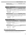
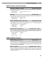
SMS Sending Input Parameters
Telephone number for SMS
Function No.:600
The telephone number to which an SMS is sent upon SMS input activation. If
blank, the function is off.
Setting options:
Default setting:
0-16 characters (0-9,*,#,+)
blank
SMS text
Function No.: -
The SMS text to be sent to the preset telephone number. If the SMS text is
blank, SMS with signal strength is sent.
Setting options:
0-40 characters
Default setting:
blank
Send if activated longer than [ms]
Function No.: 601
Set the SMS activation time necessary for SMS sending. This parameter prevents
SMS sending in the event of short-time activation. If a "0" is selected, SMS is
sent immediately upon the input activation.
Setting options:
0-25500 ms
Setting step:
100 ms
Default setting:
0 ms
Timeout after sending [s]
Function No.:
602
Set the Time of inactivity after SMS sending. During this timeout no SMS is sent
even if the SMS input gets activated. This prevents sending multiple SMS units in
the case of repeated activation of the input.
Setting options:
0-2550 s
Setting step:
Default setting:
10 s
0s
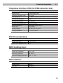
GSM & SIM Parameters
UMTS/GSM operator lock
Function No.:
-
Provider blocking is set by manufacturer in SmartGate UMTS. If 2N® SmartGate
UMTS is blocked to a UMTS/GSM provider, no other UMTS/GSM provider's SIM
card can be used. If an unacceptable SIM card is used, the UMTS/GSM module
does not register to UMTS/GSM and the UMTS/GSM network LED flashes quickly
on the 2N® SmartGate UMTS panel.
CLIR - incognito
Function No.:
701
Sets the calling line identification restriction (CLIR) for outgoing calls from
SmartGate UMTS. Attention, before enabling it is necessary to activate this
feature by UMTS/GSM operator, otherwise outgoing calls can be rejected by
UMTS/GSM network.
47
Table of Parameters
3.2
Setting options:
-According to provider (0) - depending on how the
function is selected in the UMTS/GSM network
-Activation (1) - ID is not sent.
-Suppression (2) - ID is always sent.
Default setting:
According to provider
Roaming enable/disable
Function No.:
702
You can make 2N® SmartGate UMTS work even if it is registered to a foreign
UMTS/GSM network.
Setting options:
-Disable (0) -The UMTS/GSM module logs out of a
foreign network and attempts to register again in within
5 minutes.
-Enable (1) - 2N® SmartGate UMTS works in any
UMTS/GSM network.
Default setting:
Disable
GPRS APN
Function No.: -
GPRS APN (Access Point Name) for automatic setting.
Setting options:
0-40 characters
Default setting:
blank
Wireless network selection
Function No.: -
Select the type of network used to connection.
Setting options:
UMTS+GSM, only UMTS, only GSM
Default setting:
UMTS+GSM
Call Handover workaround
Function No.:
703
This parameter offers a workaround to prevent problems during call handover
into the 1900 MHz (or 1800 MHz) band, caused by non-conforming
configurations of the 1900 MHz (or 1800 MHz) UMTS/GSM network.
Setting options:
-Disable (0) - Disable workaround.
-Enable (1) - Enable workaround. Select only when
handover into a 1800/1900MHz band fails.
Default setting:
Disable
Time period for low credit checking [h]Function No.:
710
Set to change time interval between credit checks. If your credit drops under
defined value, 2N® SmartGate UMTS sends SMS "LOW CREDIT". The "0" setting
means that the function is disabled.
Setting options:
0-255 h
Step:
Default setting:
1h
0
Code for credit checking
Function No.:
711
Credit in prepaid SIM cards is checked by network function, which displays text
message on mobile phone display. Code of network function must be terminated
with "#" symbol.
48
Table of Parameters
3.2
ATTENTION - find out if you have to pay for this function. Every check can lower
your credit.
Setting options:
Default setting:
0-8 characters (0-9,*,#,+)
blank
Minimal credit
Function No.:
712
Set minimal credit value to send warning SMS "LOW CREDIT". If credit is lower
then given value, warning SMS is send after every credit check, until you
recharge your SIM card.
Setting options:
Step:
Default setting:
0-999
1
0
Credit value position in received SMS
Function No.:
713
If there are more numbers except credit value in text answer (e.g. date, time
and so on) 2N® SmartGate UMTS seeks the number corresponding with credit
value from given position in text. The seek algorithm skips every non-number
character. If credit value is the first number in text you can leave setting 0. If
there are other numbers before credit value, set parameter to text position, from
which the algorithm will seek.
Setting options:
Step:
Default setting:
0-180
1
0
Telephone number for service SMS
Function No.:
714
Telephone number for service SMS. The number is common for GGMC SMS and
"LOW CREDIT" SMS on prepaid SIM cards.
Setting options:
0-16 characters (0-9,*,#,+)
Default setting:
blank
Service Parameters
Hardware version
Function No.:
-
2N® SmartGate UMTS hardware version - for information only (cannot be
modified). Must be used for communication with the manufacturer.
Firmware version
Function No.:
-
2N® SmartGate UMTS firmware version - 2N® SmartGate UMTS central
processor program version. The manufacturer can issue upgrades to extend
functions. To load new firmware into 2N® SmartGate UMTS use the Upgrade
function. Keep communicating with the manufacturer.
Serial number
Function No.: -
2N® SmartGate UMTS serial number - for information only (cannot be changed).
Must be used for communication with the manufacturer.
49
Table of Parameters
UMTS/GSM operator lock
3.2
Function No.: -
Refer to GSM & SIM Parameters.
Time period for GGMC SMS [h]
Function No.:970
Time interval for GGMC SMS sending. GGMC = GSM Gateway Monitoring Centre.
The "0" setting means that the function is disabled.
Setting options:
Step:
Default setting:
0-255 h
1h
0
Telephone number for service SMS
Function No.:714
Telephone number for service SMS. The number is common for GGMC SMS and
"LOW CREDIT" SMS on prepaid SIM cards.
Setting options:
0-16 characters (0-9,*,#,+)
Default setting:
blank
Initialization
All programmable parameters are arranged in tables according to their functions.
You can initialize either all parameters at once or one table of parameters.
Telephone line initialization FXS
Function No.: -
Initialization of all parameters necessary for the telephone line FXS.
Telephone line initialization FXO
Function No.: -
Initialization of all parameters necessary for the telephone line FXO.
Call table initialization FXS
Function No.: -
Initialization of all parameters related to FXS routing table.
Call table initialization FXO
Function No.:
Initialization of all parameters related to FXO routing table.
Call table initialization GSM
Function No.: -
Initialization of all parameters related to UMTS/GSM routing table.
Initialization of GSM & SIM
Function No.: -
Initialization of all parameters related to the UMTS/GSM network and SIM card
(except the PIN code).
SMS input initialization
Function No.: -
Initialization of all parameters for SMS sending upon SMS input activation.
50
Table of Parameters
Global initialization
3.2
Function No.: 999
Initialization of all 2N® SmartGate UMTS parameters including the PIN and
service password.
Only Global initialization can be done by phone line programming. As parameter
must be used. This operation
of this function service password followed by
isn’t followed by confirmation tone. Successful setting is followed by pause
(aprox.10s), during this time period is performed reset of configuration memory.
Than is the gateway restarted.
Security Parameters
PIN – value
Function No.: 700
Fill in the PIN value for automatic PIN entering upon 2N® SmartGate UMTS
power up. It is applied only if the SIM card is PIN secured. If the given PIN fails
to match the SIM, it is deleted automatically. If entered via a telephone line
upon 2N® SmartGate UMTS start, the PIN is stored automatically.
Setting options:
0, 4-8 characters (0-9)
Upon full initialization:blank
Service password
Function No.: 900
Fill the service password for programming via a telephone line. Some parameters
can be programmed by DTMF dialing and so the access to programming must be
password-protected.
Setting options:
4-8 characters (0-9)
Upon full initialization:
12345
51
4
4.
Function and
Use
This section describes the basic and extending functions of the product
2N® SmartGate UMTS .
Here is what you can find in this section:
n
Voice function
n
SMS Sending Input
n
USB – monitoring, internet, SMS
n
SIM Card PIN protection.
53
Voice function
4.1
4.1 Voice function
Outgoing and incoming call establishing procedures is for illustration described for
analog phone connected to FXS interface and extension line of PBX connected to
FXO interface on SmartGate UMTS. In case of other equipment connection, please
check SmartGate UMTS’s function by connecting a phone.
Suppose that a SIM card has been inserted, the PIN code entered or not required,
the antenna connected and 2N® SmartGate UMTS registered to UMTS/GSM
network – the UMTS/GSM network LED is permanently on and you can hear the dial
tone upon line off-hook.
DialThru gateway
Extension line of PBX is connected to FXO interface and phone is connected to FXS
interface on SmartGate UMTS.
Outgoing call on FXS interface
1. Hook off the telephone, you can hear the dial tone and the Line LED starts
flashing.
2. Dial the required subscriber number. 2N® SmartGate UMTS receives tone
dialing (DTMF) by default. If your telephone transmits pulse dialing only,
program 2N® SmartGate UMTS to receive pulse dialing. The delay between
dialed digits may not exceed 5 s (programmable parameter). The number is
evaluated as complete after this timeout.
3. A short delay follows the last-dialed digit for 2N® SmartGate UMTS to await
further dialing. Then, the dialing end is signaled and connection is established.
4. Prefix of dialed number is compared with filled rows of FXS routing table. The
call is rejected, routed to UMTS/GSM network or to FXO interface according to
the routing table.
5. If the called subscriber is available, you can hear the ringing tone. If not, you
can hear the busy tone or any of the UMTS/GSM provider’s messages.
6. When the called subscriber answers the call, a call is established. The Line LED
is permanently on during the call (Orange for calls to UMTS/GSM. GreenOrange alternate for FXS-FXO calls).
7. Hang up to terminate the call. The Line LED goes off. If the called subscriber
hangs up first, you can hear the busy tone.
Incoming call from UMTS/GSM network
1. The CLI is compared with filled rows of GSM routing table. The call is rejected,
routed to FXS interface – connected phone, or to FXO interface according to the
routing table. Routing to FXO interface isn’t usually used in case of DialThru
gateway.
2. Ringing on FXS interface signals incoming call. The Line LED flashes during
ringing. If programmed so, 2N® SmartGate UMTS transmits the CLIP by FSK
between the first and second rings. Advanced telephone sets are able to display
the CLI.
3. Hook off the phone to establish the call. The Line LED is permanently on during
the call.
54
Voice function
4.1
4. Hang up to terminate the call. The Line LED goes off. If the called subscriber
hangs up first, you can hear the busy tone.
Incoming call on FXO interface
1. 2N® SmartGate UMTS detects a ringing signal and immediately interconnects it
to FXS interface – the phone starts to ring.
2. The CLIP transmitting must provide connected PBX.
3. If you hook off the phone the call is established.
Gateway for extension line of PBX
Extension line of PBX is connected to FXO interface on SmartGate UMTS. FXS
interface remains unconnected.
You have to program parameter “FXO call route to” for proper function on FXO
interface. You can fill in some rows in FXO routing table to reject given calls, for
automatic call routing etc.
Fill in GSM routing table to route an incoming UMTS/GSM calls to FXO interface.
It is necessary to set up conditions for call-disconnect detection from PBX. If
2N® SmartGate UMTS detects busy tone or continuous tone from PBX, it
disconnects the established UMTS/GSM call.
Outgoing call on FXO interface
1. 2N® SmartGate UMTS detects a ringing signal from PBX and, if it is possible to
establish UMTS/GSM call, it hooks off the line after preprogrammed number of
rings. 2N® SmartGate UMTS transmits dial tone and green LED for line starts
flashing.
2. Dial the UMTS/GSM subscriber number using DTMF. The delay between dialed
digits may not exceed 5 s (programmable parameter). The number is evaluated as
complete after this timeout.
3. A short delay follows the last-dialed digit for 2N® SmartGate UMTS to await
further dialing. Then, the dialing end is signaled and connection is established.
4. Prefix of dialed number is compared with filled rows of FXO routing table. The
call is rejected or routed to UMTS/GSM network according to the routing table.
5. If the called subscriber is available, you can hear the ringing tone. If not, 2N®
SmartGate UMTS hangs up.
6. When the called subscriber answers the call, a call is established. The green
Line LED is permanently on during the call.
7. Hang up to terminate the call. PBX sends busy tone to SmartGate UMTS’s
subscriber line, 2N® SmartGate UMTS detects it and disconnects the
UMTS/GSM call.
Incoming call from UMTS/GSM network
1. The CLI is compared with filled rows of GSM routing table. The call is rejected,
or routed to FXO interface – extension line of PBX according to the routing
table.
2. 2N® SmartGate UMTS hooks off the line. If there is filled in the “Dial in”
parameter for given CLI, 2N® SmartGate UMTS dials it using DTMF.
55
Voice function
4.1
3. The UMTS/GSM subscriber hears the ringing tone from PBX if the automatic dial
in function was applied, if not he hears dial tone from PBX and he can dial
required extension himself.
4. The call termination is the same as in case of outgoing call.
Gateway for trunk line of PBX
Outgoing and incoming call establishing procedures is for illustration described
for analog phone connected to FXS interface. The rules for call establishing in case
of trunk line connection are the same, you have to program your PBX to route
UMTS/GSM calls to SmartGate UMTS. We strongly recommend to check SmartGate
UMTS’s function by connecting a phone in case of interconnection with PBX trunk
line.
Outgoing call on FXS interface
1. Hook off the telephone, you can hear the dial tone and the orange Line LED
starts flashing.
2. Dial the required UMTS/GSM subscriber number. 2N® SmartGate UMTS
receives tone dialing (DTMF) by default. If your telephone transmits pulse
dialing only, program 2N® SmartGate UMTS to receive pulse dialing. The delay
between dialed digits may not exceed 5 s (programmable parameter). The number
is evaluated as complete after this timeout.
3. A short delay follows the last-dialed digit for 2N® SmartGate UMTS to await
further dialing. Then, the dialing end is signaled and connection is established.
4. Prefix of dialed number is compared with filled rows of FXS routing table. The
call is rejected, or routed to UMTS/GSM network according to the routing table.
5. If the called subscriber is available, you can hear the ringing tone. If not, you
can hear the busy tone or any of the UMTS/GSM provider’s messages.
6. When the called subscriber answers the call, a call is established. The orange
Line LED is permanently on during the call.
7. Hang up to terminate the call. The Line LED goes off. If the called subscriber
hangs up first, you can hear the busy tone.
Incoming call from UMTS/GSM network
1. The CLI is compared with filled rows of UMTS/GSM routing table. The call is
rejected, or routed to FXS interface – connected phone according to the routing
table.
2. Ringing on FXS interface signals incoming call. The orange Line LED flashes
during ringing. If programmed so, 2N® SmartGate UMTS transmits the CLIP by
FSK between the first and second rings. Advanced telephone sets are able to
display the CLI.
3. Hook off the phone to establish the call. The Line LED is permanently on during
the call.
4. Hang up to terminate the call. The Line LED goes off. If the called subscriber
hangs up first, you can hear the busy tone.
56
Voice function
4.1
Automatic Call ("BabyCall")
If the BabyCall function is enabled on FXS interface, a pre-programmed timeout
is counted down after off-hook. If you don’t start dialing within this timeout, 2N®
SmartGate UMTS signals dialing end and starts to establish a call to the preprogrammed number using UMTS/GSM network automatically – from now 2N®
SmartGate UMTS behaves as if a standard outgoing call to UMTS/GSM had been
established. Any dialing during the BabyCall timeout cancels this function and a
standard outgoing call can be made.
ME- Mobility Extension
ME function takes place during ringing on FXS interface if 2N® SmartGate UMTS
is programmed as DialThru gateway.
Fill in telephone number for ME function and number of rings to ME function start
on FXO routing table sheet.
1. 2N® SmartGate UMTS detects a ringing signal and immediately interconnects it
to FXS interface – the phone starts to ring.
2. If there is no call connection before the pre-programmed number of rings, 2N®
SmartGate UMTS simultaneously establishes call to UMTS/GSM network. Some
timeout take place between UMTS/GSM call establishing start and ringing of
mobile phone.
3. As long as 2N® SmartGate UMTS detects ringing on FXO interface, connected
analog and UMTS/GSM phones ring.
4. You can receive the call on analog line as well as on your mobile phone.
5. During call received on mobile phone you can send FLASH to PBX, for special
PBX functions, by preprogrammed DTMF code.
If you want repeatedly temporarily disable and afterwards enable the ME
function, fill in Password for ME activation/disabling. If password is filled in:
1. Hook off the phone.
2. For temporarily disabling the function dial the password and confirm by
For activation the function dial the password and confirm by
3. Hang up.
.
Tariff pulses 16 or 12 kHz
2N® SmartGate UMTS has tariff pulse transmitter on FXS interface. You can use
tariff pulses for outgoing call pricing. 2N® SmartGate UMTS offer pseudotariff only
– tariff metering doesn’t correspond to real price of call, tariff pulses are
transmitted according to programmed parameters and call duration. You must
program specific parameters in FXS routing table to set tariff metering for different
prefixes of dialed numbers. Tariff metering is transmitted only during calls to
UMTS/GSM network. Connected PBX must provide the tariff metering during calls to
FXO interface.
You can also program 2N® SmartGate UMTS to transmit tariff pulses as call
connect/disconnect signaling if your PBX cannot receive telephone line polarity
reversal signaling.
57
Voice function
4.1
Configuration of network services
2N® SmartGate UMTS provides some of network services to improve possibility of
usage. The configuration is done by standard Star-Hash codes you can know from
mobile phones.
To configure these services:
1.
Hook off the telephone, you can hear the dial tone.
2.
Enter the Star-Hash code described below.
3.
Wait for information tone. You may wait about 3 seconds.
4.
Hook on.
Information tones:
Confirmation - OK:
n
Confirms that the service was configured correctly.
Confirmation - bad:
n
Service was not correctly configured
n
Service isn’t activated by your provider
Confirmation - service activated:
n
Confirms that the service was configured correctly and the service is
activated.
Confirmation - service deactivated:
n
Confirms that the service was configured correctly and the service is
deactivated.
Call forwarding
For forwarding activation you must specify <Telephone number> the calls will be
forwarded to. You may specify <Call type>, if you want to forward specified call
type only. You may specify <Delay time> in seconds for forwarding if no answer
too.
Description of <Call type> field codes:
Voice:
Data:
Fax:
58
Voice function
4.1
Call forwarding unconditional
If activated, incoming calls will be always forwarded to the configured telephone
number.
Activation for all call types:
<Telephone number>
Activation for selected call type:
<Telephone number>
<Call type>
Deactivation:
Status check:
Call forwarding if busy
If activated, incoming calls will be forwarded to the configured telephone number
if there is call in progress on SmartGate UMTS.
Activation for all call types:
<Telephone number>
Activation for selected call type:
<Telephone number>
<Call type>
Deactivation:
Status check:
Call forwarding if no answer
If activated, incoming calls will be forwarded to the configured telephone number
if incoming call isn’t answered during specified timeout. Default timeout is 20
seconds.
Activation for all call types:
<Telephone number>
Activation for selected call type:
<Telephone number>
<Call type>
59
Voice function
4.1
Activation for all call types and specified delay time:
<Telephone number>
<Delay time>
Activation for selected call type and specified delay time:
<Telephone number>
<Call type>
<Delay time>
Deactivation:
Status check:
Call forwarding if not accessible
If activated, incoming calls will be forwarded to the configured telephone number
if your 2N® SmartGate UMTS is not accessible in the UMTS/GSM network.
Activation for all call types:
<Telephone number>
Activation for selected call type:
<Telephone number>
<Call type>
Deactivation:
Status check:
Call waiting
If the call waiting is activated the incoming call isn’t refuse if there is call in
progress on SmartGate UMTS. If there is the other incoming call during connected
call it will be indicated by tone. See 0. for multiple calls management.
Activation:
Deactivation:
Status check:
60
Voice function
4.1
Call hold
Check if your network supports the service before you use it.
This service relates to Call waiting described in 0. If there is call waiting on the
line, you have more possibilities what to do. Every action is made by FLASH and
DTMF code:
To terminate all held calls, or reject waiting call dial:
To terminating active call and accept the held or waiting call dial:
To place the active call on hold and accept the held or waiting call (switching
between two calls) or
To place the active call on hold to have possibility to dial other outgoing call dial:
To place all held calls to active calls and set up conference call dial:
To connect the two calls (active and held) and disconnect the 2N® SmartGate
UMTS from both calls dial:
61
SMS Sending Input
4.2
4.2 SMS Sending Input
This universal input is intended especially for reporting alarm or error statuses of
any equipment provided with the appropriate contact (a relay contact, e.g.).
By activating this input (electric input pin interconnection) you send one SMS to
one pre-programmed telephone number.
Caution
n
Do not use in life-supporting or property-protection applications because
of the character of SMS service and 2N® SmartGate UMTS equipment.
The manufacturer shall not be liable for health and property damage
incurred as a result of SMS sending failure.
62
Data connection using USB
4.3
4.3 Data connection using USB
2N® SmartGate UMTS can be used as high speed wireless modem to connect your PC
to internet. Technology HSDPA, UMTS. EDGE or GPRS are supported.
Connection to internet–Sierra Wireless module version
For Internet connection management is used program AirCard Watcher.
Internet connection setting
1. Install program ‘Watcher_Generic_B2849.msi’ from CD.
Note
n
In some versions of Windows 7 is known bug, when runtime error
connected with VBscript occurs, the bug must be fixed. Use Microsoft
patch ‘RegisterWindowsScriptEngine.msi’, which is included on CD.
2. Connect 2N® SmartGate UMTS k PC using USB cable to PC ant switch it on.
3. The drivers will be installed automatically and the program AirCard Watcher
starts.
SMS Express
Setting
Provider
4. Use button Connect for connection to internet. For the first run you will be
asked to set profile for connection.
5. For profile setting you have to fill the name of profile and the Access point
name – APN (e.g ‘internet’). For some providers is necessary to set Username
and Password. All this information are to be obtained from you internet
provider.
63
Data connection using USB
4.3
APN
6. Confirm the saving of your profile (OK). You will be connected to internet
automatically.
SMS sending and receiving
Program AirCard Watcher supports sending and receiving SMS – select menu SMS
Express. Simple SMS application is activated.
Connection to internet – Simcom module version
USB driver installation
For communication over USB port of EasyGate is necessary to install USB driver. The
installation is usually automatic after connection to USB port by delivered USB cable.
The connection is described in detail in part 3.1 - “Installation and setting of EasyGate
PCManager”.
Internet connection
You can use the provider’s installation wizard in case it supports the module used in
gateway (Cinterion MC55i-w for GSM version, Simcom SIM5320E (A, J) for UMTS
version). When this wizard is not available, you have to use manual setting according
following instructions.
Module driver installation
For communication using module is necessary to install modem driver from CD-ROM
Easy Gate.
Driver for MC55i-w on CD is named: ‘mdm2n_vx.x.inf,x’ (x – driver version).
Drivers for SIM5320 are available for 32 and 64 bits Windows systems, they are
placed in appropriate directories.
APN setting
For internet connection is necessary to set the APN of your mobile provider. It could
be set in gateway using PCManager (GSM&SIM - GPRS APN) or in modem extra
settings in PC:
Example: at+cgdcont=1,"IP","internet.t-mobile.cz"
64
Data connection using USB
4.3
APN name must be received from your mobile provider, in example is the APN of
T-Mobile Czech republic used.
Network connection setting
· Ask you mobile provider for Internet connection instructions because they can be
different for each provider (especially the telephone number to be dialed, eventually
Username, Keyword, DNS, etc.). Set phone connection in your PC using Network
connection setting and select appropriate modem. Set the connection parameters
(Username, Password, Dial number) according to information from your mobile
provider (obviously Username ‘internet’, Keyword is empty an Dial number
*99***1#). Finally use button ‘Dial’ to establish connection to internet.
Caution
n
Mobile providers mostly specify the *99# number to be dialed for GPRS
connection in their instructions. Cinterion GSM modules require the
*99***1# format.
SMS sending and receiving
It is possible to send and receive SMS units using appropriate AT commands. There
are a number of PC programs that are based on this principle. You can send and
receive SMS even during EasyGate voice calls.
65
SIM Card PIN protection
4.4
4.4 SIM Card PIN protection
If a SIM card is PIN-protected and the PIN is not programmed in SmartGate UMTS,
UMTS/GSM LED indicates the state and the PIN tone is transmitted on telephone
line.
PIN Entering by PCManager
Like other parameters, the PIN code can be entered using a PC programming tool.
The PIN will be entered automatically upon every 2N® SmartGate UMTS power up.
PIN Entering via Telephone Line
PIN entering via a telephone line connected to FXS interface:
1. Hook off the phone, you can hear the PIN tone.
2. Enter the PIN using the DTMF. You can cancel the wrong PIN by entering
of a
, or you can hang up before sending a
.
3. To confirm enter a
.
4. If you hear the busy tone in a while (a few seconds), you have entered
the PIN correctly. Hang up and wait for registering to the UMTS/GSM
network.
5. If you hear the PIN tone again in a while, you have entered a wrong PIN.
Re-enter the PIN correctly.
6. If you hear the PUK tone in a while, you have entered a wrong PIN and
the SIM card is blocked. Use the mobile phone to unblock the SIM card.
PIN entering via a telephone line connected to FXO interface if 2N® SmartGate
UMTS is used as gateway for extension line of PBX:
1. Dial the SmartGate UMTS’s extension number on your PBX. 2N®
SmartGate UMTS detects ringing and after off hook generates the PIN
tone.
2. Enter the PIN using the DTMF. You can cancel the wrong PIN by entering
of a
, or you can hang up before sending a
.
3. To confirm enter a
.
4. If 2N® SmartGate UMTS after a while (a few seconds) hangs up, you
have entered the PIN correctly.
5. If you hear the PIN tone again in a while, you have entered a wrong PIN.
Re-enter the PIN correctly.
6. If you hear the PUK tone in a while, you have entered a wrong PIN and
the SIM card is blocked. Use the mobile phone to unblock the SIM card.
A correctly entered PIN is stored in SmartGate UMTS’s memory as if you had
programmed it using the PCManager. The PIN will be entered automatically upon
every 2N® SmartGate UMTS power up.
66
SIM Card PIN protection
4.4
Automatic PIN Entering
You need not enter the PIN upon power up if it is stored in 2N® SmartGate UMTS –
it is entered automatically. This function is useful in case of power failure; 2N®
SmartGate UMTS is operable in a short time after power recovery without any
intervention by the operating staff.
Caution!
n
One PIN entering option is exhausted by the attempt to enter the PIN
automatically upon SIM card or PIN change. If wrong, the automatically
entered PIN is cleared from the internal memory to avoid another false
attempt upon next power on. There are still two manual PIN-entering
attempts after such unsuccessful automatic entering. To prevent the
unsuccessful automatic PIN entering, delete or program properly the 2N®
SmartGate UMTS PIN using the PCManager in the case of SIM card
change.
67
5
5.
Technical
parameters
This section describes the technical parameters of the product
2N® SmartGate UMTS.
69
Technical Parameters
5.1
5.1 Technical Parameters
Product versions
Sierra Wireless
Ordering numbers 501428x
Sierra Wireless backup
version
Ordering numbers 501438x
Simcom
Ordering numbers 501448
Simcom backup verzion
Ordering numbers 501458x
Sierra UMTS/GSM
SL8082 – Euro version
UMTS: 900/2100 MHz
UMTS/GSM
module, bandwidth
GSM/EGSM: 850/900/1800/1900 MHz
SL8080 – US version
UMTS 900/1900 MHz
GSM/EGSM: 850/900/1800/1900 MHz
0,25W UMTS 900/1900/2100 MHz
Transmission power
Receiver sensitivity
2W
EGSM 850 / 900 MHz,
1W
GSM 1800 / 1900 MHz
-108 dBm
UMTS 900/1900/2100 MHz
-106 dBm
GSM
850/900/1800/1900 MHz
HR+FR+EFR Half rate+Full rate+Enhanced full rate
Audio
Echo cancellation, Echo suppression, WDCMA AMR
Adaptive Multirate
CSD max. 14.4 kbps;Coding scheme CS 1-4,MCS 1-9
GPRS Class 10, 4+2, max. 85.6 kbps
DATA
EDGE Class 12, 4+2, max 236 kbps
UMTS/HSDPA cat.8, MS Class A (Simultaneous Voice
and Data), max 3,6Mbps downlink, 384 kbps uplink
Antenna
850/900/1800/1900/2100 MHz 50 W
SMA antenna connector
70
Technical Parameters
SIM card
5.1
3V/1,8 plug-in
Simcom UMTS/GSM
SIM5320E – Euro version
UMTS: 900/2100 MHz
GSM/EGSM: 850/900/1800/1900 MHz
UMTS/GSM
module, bandwidth
SIM5320A – US version
UMTS 850/1900 MHz
GSM/EGSM: 850/900/1800/1900 MHz
SIM5320J – Japanese version
UMTS 850/2100 MHz
GSM/EGSM: 850/900/1800/1900 MHz
0,25W UMTS 850/900/1900/2100 MHz
Transmission power
Receiver sensitivity
Audio
2W
EGSM 850 / 900 MHz,
1W
GSM 1800 / 1900 MHz
-106 dBm
HR+FR+EFR (Half rate+Full rate+Enhanced full rate)
Echo cancellation, Echo suppression
CSD max. 14.4 kbps
GPRS Class 12, max. 85.6 kbps (DL), 42,8 kbps (UL)
DATA
EDGE Class 12 max. 236,8 kbps (DL), 118 kbps (UL)
WCDMA max. 384 kbps (DL), 384 kbps (UL)
HSDPA max 3,6 Mbps (DL)
Antenna
SIM card
850/900/1800/1900/2100 MHz 50 W
SMA antenna connector
3V/1,8 plug-in
71
Technical Parameters
5.1
Power Supply
DC power supply
10 to 16 V DC (accumulator 12V)
12V consumption
Supply connector
Standby
100 mA
Call/data
max. 500 mA
DC Jack 5,5/2,1 mm positive to center
Power source must meet the criteria for SELV standard
Battery backup (optional)
Accumulator type
Charging cell NiMh size AA
Number of pieces
4
Power consumption
batteries
from Standby
Call/data
Charging current
300 mA
max. 1200 mA
Typ. 60 mA, max 120 mA, regulated
Accumulators are not part of delivery
Telephone Interface FXS (for PBX external line or
phone set)
Interface type
2-wire analog, FXS
Telephone connector type
RJ 12, 6/2
Line impedance
600 W
Loop voltage on hook
48 V DC
Loop current
max. 40 mA
Loop resistance
max. 800 W
Tone frequency
adjustable, default 425 Hz
Dialing type
tone (DTMF) or pulse
Ringing voltage
42 Vrms 50/25 Hz
Calling line identification
CLI during ringing according to ETSI FSK
Tariff pulses
f=16/12 kHz ; Umin=100 mVef on 200 W
Answer supervision
polarity reversal, 12/16 kHz pulses
72
Technical Parameters
5.1
Telephone Interface FXO (for PBX extension line)
Interface type
2-wire analog, FXO
Telephone connector type
RJ 12, 6/2
Line impedance
Zr (TBR21) or 600 W (According to model of Gateway)
On-hook DC resistance
1 MW
Off-hook line current
10 - 65 mA
Off-hook line voltage (typ.)
4,5 V for 25 mA
Dial tone frequency
adjustable, default 425 Hz
Dialing type
tone (DTMF)
Ringing voltage
Min. 20 Vrms 25-50 Hz
Ringing impedance
4 - 10 kW / 50 Hz
Dial thru parameters
Voltage drop (typ.)
1,7V / 25 mA
Closed loop resistance (typ.)
6W
SMS Sending Input
Closed loop resistance
max. 1 kW
Open loop resistance
Min. 25 kW
Input overvoltage protection
max. +/- 12 V
Data Interface
Interface type
USB 2.0
Connector
USB type B
73
Technical Parameters
5.1
Others
Dimensions (w/o connectors)
170 x 130 x 45 mm
Operating temperature
0°C to 45°C
Operating status signaling
4 LEDs (on, UMTS/GSM network, line, data)
Signal strength indicator
74
6
6.
Supplementary
Information
This section describes supplementary information of the product
2N® SmartGate UMTS.
Here is what you can find in this section:
n
Regulations and directives
n
Troubleshooting
n
List of Abbreviations
n
General Instructions and Cautions.
75
Regulations and directives
6.1
6.1 Regulations and directives
2N® SmartGate UMTS conforms to the following directives and regulations:
n
Directive 1999/5/EC of the European Parliament and of the Council, of 9
March 1999 – on radio equipment and telecommunications terminal equipment
and the mutual recognition of their conformity
n
Directive 2006/95/EC of the European Parliament and of the Council of 12
December 2006 on the harmonisation of the laws of Member States relating to
electrical equipment designed for use within certain voltage limits
n
Directive 2004/108/EC of the European Parliament and of the Council of 15
December 2004 on the approximation of the laws of the Member States relating
to electromagnetic compatibility and repealing Directive 89/336/EEC
n
Directive 2002/96/EC of the European Parliament and of the Council of 27
January 2003 on waste electrical and electronic equipment
n
Regulation (EC) No 1907/2006 of the European Parliament and of the Council
of 18 December 2006 concerning the Registration, Evaluation, Authorisation and
Restriction of Chemicals (REACH), establishing a European Chemicals Agency,
amending Directive 1999/45/EC and repealing Council Regulation (EEC) No
793/93 and Commission Regulation (EC) No 1488/94 as well as Council Directive
76/769/EEC and Commission Directives 91/155/EEC, 93/67/EEC, 93/105/EC and
2000/21/EC
n
Directive 2002/95/EC of the European Parliament and of the Council of
27 January 2003 on the restriction of the use of certain hazardous substances in
electrical and electronic equipment
76
Troubleshooting
6.2
6.2 Troubleshooting
For tips for the solution of other potential problems see faq.2n.cz.
´
No LED is on after power up
u Check the power supply.
´
All LEDs are on. No call is currently in progress.
u 2N® SmartGate UMTS is in the special PCManager-based programming
mode - exit the PCManager to reset SmartGate UMTS
u Try to switch 2N® SmartGate UMTS off and on, the LEDs should go off in
3s and signal the status of SmartGate UMTS
´
2N® SmartGate UMTS does not register to UMTS/GSM
u Check the SIM card.
u Check the PIN.
u Check the antenna connection.
u Select a place with a good UMTS/GSM signal.
´
No tone can be heard after line off-hook
u Check the telephone line connection.
u 2N® SmartGate UMTS is not initialized properly upon start (approx. 10s
after power up).
u 2N® SmartGate UMTS is not supplied with power.
´
2N® SmartGate UMTS keeps transmitting a tone during dialing, not receiving
the dialing
u Select the correct dialing type (DTMF or pulse).
´
Voice disturbance on telephone lines during UMTS/GSM call
u Check signal strength using PCManager monitor. Place 2N® SmartGate
UMTS to place with good UMTS/GSM signal.
u Check distance between telephone lines and SmartGate UMTS’s antenna.
Distance between antenna and other telecommunication systems should
be as long as possible.
u If there are still problems, use the antenna with coax cable.
77
Troubleshooting
´
6.2
2N® SmartGate UMTS does not communicate with PC
u Check the serial cable connection.
u Check the COM number setting on PC.
u Check the COM parameters (1200-115200 bps, 8N1).
u 2N® SmartGate UMTS is not registered to UMTS/GSM network.
u A dialing or outgoing call establishing process takes place on SmartGate
UMTS.
u An incoming call is ringing on SmartGate UMTS.
78
List of Abbreviations
6.3
6.3 List of Abbreviations
n
APN (Access Point Name)
Necessary for the GPRS service.
n
CLIP (Calling Line Identification Presentation)
n
CSD (Circuit Switched Data)
n
COM
A PC Serial port.
n
DTMF (Dual Tone MultiFrequency)
Tone dialling.
n
FSK (Frequency Shift Keying)
A transmission protocol using variable signal frequencies for logic level
encoding.
n
FXO
An interface electrically identical with a standard telephone
(opposite side = FXS interface).
n
FXS
A telephone interface allowing a standard telephone connection
(opposite side = FXO interface).
n
FW (Firmware)
Similar to SW, a term for the central microprocessor program.
n
GSM (Group Switched Mobile system)
The present-day standard digital mobile telephone network.
n
GPRS (General Packet Radio Service)
High-speed data transmission for UMTS/GSM networks.
n
HW (Hardware)
An electronic device, circuit, board, component, etc. in this context.
n
P(A)BX (Private (Automatic) Branch Exchange)
n
PC (Personal Computer)
A personal computer based on the IBM PC standard.
n
PIN (Personal Identification Number)
A SIM card securing password.
n
PSTN
Public Switched Telephone Network.
n
PUK (Personal Unblocking Key)
A password used for releasing a blocked SIM card after repeated wrong PIN
entering.
n
RS-232C
A PC serial port standard.
n
SIM (Subscriber Identity Module)
A chip-equipped module to be inserted in a UMTS/GSM device for
identification.
n
SmG
2N® SmartGate UMTS
79
List of Abbreviations
6.3
n
SMS (Short Message Service)
A term for the system and one unit (message).
n
SW
Software.
n
TTL (Transistor-Transistor Logic)
A standard digital technology defining voltage for levels 0 and 1.
n
PSTN
Public Switched Telephone Network
n
UMTS (Universal Mobile Telecommunications System)
n
WCDMA
Wideband Code Division Multiple Access – technology of wireless transmitting
in UMTS network, allows higher data transmit rate than
80
General Instructions and Cautions
6.4
6.4 General Instructions and Cautions
Please read this User Manual carefully before using the product. Follow all instructions
and recommendations included herein.
Any use of the product that is in contradiction with the instructions provided herein
may result in malfunction, damage or destruction of the product.
The manufacturer shall not be liable and responsible for any damage incurred as a
result of a use of the product other than that included herein, namely undue
application and disobedience of the recommendations and warnings in contradiction
herewith.
Any use or connection of the product other than those included herein shall be
considered undue and the manufacturer shall not be liable for any consequences
arisen as a result of such misconduct.
Moreover, the manufacturer shall not be liable for any damage or destruction of the
product incurred as a result of misplacement, incompetent installation and/or undue
operation and use of the product in contradiction herewith.
The manufacturer assumes no responsibility for any malfunction, damage or
destruction of the product caused by incompetent replacement of parts or due to the
use of reproduction parts or components.
The manufacturer shall not be liable and responsible for any loss or damage incurred
as a result of a natural disaster or any other unfavourable natural condition.
The manufacturer shall not be held liable for any damage of the product arising during
the shipping thereof.
The manufacturer shall not make any warrant with regard to data loss or damage.
The manufacturer shall not be liable and responsible for any direct or indirect damage
incurred as a result of a use of the product in contradiction herewith or a failure of the
product due to a use in contradiction herewith.
All applicable legal regulations concerning the product’s installation and use as well as
provisions of technical standards on electric installations have to be obeyed. The
manufacturer shall not be liable and responsible for damage or destruction of the
product or damage incurred by the consumer in case the product is used and handled
contrary to the said regulations and provisions.
The consumer shall, at its own expense, obtain software protection of the product. The
manufacturer shall not be held liable and responsible for any damage incurred as a
result of the use of deficient or substandard security software.
The consumer shall, without delay, change the access password for the product after
installation. The manufacturer shall not be held liable or responsible for any damage
incurred by the consumer in connection with the use of the original password.
The manufacturer also assumes no responsibility for additional costs incurred by the
consumer as a result of making calls using a line with an increased tariff.
81
General Instructions and Cautions
6.4
Electric Waste and Used Battery Pack Handling
Do not place used electric devices and battery packs into municipal waste containers.
An undue disposal thereof might impair the environment!
Deliver your expired electric appliances and battery packs removed therefrom to
dedicated dumpsites or containers or give them back to the dealer or manufacturer for
environmental-friendly disposal. The dealer or manufacturer shall take the product
back free of charge and without requiring another purchase. Make sure that the
devices to be disposed of are complete.
Do not throw battery packs into fire. Battery packs may not be taken into parts or
shirt-circuited either.
82
2N TELEKOMUNIKACE a.s.
Modřanská 621, 143 01 Prague 4, Czech Republic
Tel.: +420 261 301 500, Fax: +420 261 301 599
E-mail: [email protected]
Web: www.2n.cz
1699v1.1.0