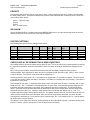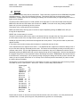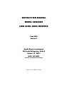
1
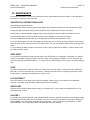
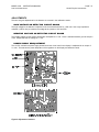
INSTRUCTION MANUAL
MODEL 6030/6025
LOW LEVEL AREA MONITOR
Sept 2000
Version 1
Health Physics Instruments
330 South Kellogg Ave, Suite D
Goleta, CA 93117
(805) 967-8422
Division of Far West Technology
Fuse at ½ A Slo Blow 5 x 20 mm
MODEL 6030
INSTRUCTION MANUAL
Low Level Area Monitor
PAGE 1
Health Physics Instruments
TABLE OF CONTENTS
I.
II.
III.
INTRODUCTION ..................................................................................................................... 2
OPERATION
2
INSTALLATION...................................................................................................................... 2
DETECTOR
DISPLAY
DETECTOR AND DISPLAY CONNECTIONS
I/O CONNECTIONS
CONNECTOR PART NUMBERS
INTERFERENCE
CONTACT CLOSURE FOR EXTERNAL ALARM
RS232
EXTERNAL INTEGRATOR RESET BUTTON
IV.
V.
FRONT PANEL 4
ALARMS
5
ALARM ACTIVATION
ALARM 1
ALARM 2
ALARM 3
FAIL
PRIORITY
NO ALARM
FACTORY SETTINGS
CHECK DISPLAY OR VIEWING THE ALARM CONDITIONS
VI.
APPENDIX I
16
17
17
18
USER TABLES
XII.
XIII.
14
14
14
14
14
14
15
16
16
CIRCUIT DESCRIPTION........................................................................................................ 16
GENERAL
DETECTOR
DISPLAY
XI.
12
12
MAINTENANCE 14
SHORTCUTS & OPERATIONAL HINTS
ZERO DRIFT
FUSE
LCD CONTRAST
DESICCANT
FAILURE 1
ADJUSTMENTS
MAINTENANCE MODE
TESTING DISPLAY
X.
11
11
CALIBRATION 12
ZERO ADJUSTMENT
CALIBRATION PROCEDURE
IX.
8
8
8
8
8
8
9
9
9
10
10
RS232 SERIAL OUTPUT....................................................................................................... 10
STATUS BYTE
BIT FUNCTION
VIII.
5
5
5
5
5
6
6
6
6
SETUP 7
PRESET
ZERO
TRIPSET
DELAY
PAUSE
ALM SETUP (ALARM SETUP)
BUZZER
DECIMAL
START TIME
FAIL TIME
TURNING THE ALARMS OFF
VII.
2
3
3
3
3
4
4
4
4
PARTS LIST 20
SCHEMATICS 27
18
MODEL 6030
INSTRUCTION MANUAL
Low Level Area Monitor
PAGE 2
Health Physics Instruments
I. INTRODUCTION
The Model 6030/6025 Area Monitor is designed to measure low levels of gamma and neutron radiation. It has
several alarms and trip points that are user set. The front panel display shows the radiation level and the status of
the instrument. The detector is model number 6030 and the display/readout is model number 6025.
II. OPERATION
The operation of the 6030/6025 is very simple. The first line of the display shows the radiation level from the detector.
It is updated every second. The second line shows the integrated dose and is updated every second. The lights on
the front panel also show the status of the alarms. The front panel controls reset the integrated dose, set the alarm
levels, and change the operational parameters.
When the instrument is first turned on there is a wait until the instrument stabilizes. The number of seconds
remaining until normal operation begins is shown on the display along with the version number of the software. The
detector may take longer than the wait period to completely stabilize to background levels, however this should not
effect the alarms because the level is close to background.
III. INSTALLATION
The 6030/6025 is easily installed. It consists of 2 parts, the detector unit (6030) and the display or readout unit
(6025). There is a single 4 wire connection between the two and a short cable is supplied with the instrument.
The detector and display can be remoted up to 100 feet. If you wish to use a longer cable you will need to assemble
your own cable. The connectors at each end of the cable are crimp type that can be easily assembled in the field.
We recommend Belden 8723 cable. This is a 2 pair shielded cable. For short distances any 4 conductor cable will
work. For longer distances or if it is used in a noisy environment we recommend a shielded cable. The connectors
are wired the same on both ends of the cable.
After setting up the instrument, review the section on ALARMS to know how to change the alarm configurations, on
SETUP to know how to change the alarm and zero settings, and on FRONT PANEL to know how to operate the
controls on the front panel.
DETECTOR
The detector is installed by first fixing the detector mounting bracket. The detector unit may be mounted in any
orientation. It is best if the side of the detector faces the radiation source. The detector sets into the mounting
bracket and is held in place with the two thumbscrews. Plug one end of the cable into the circular connector on top
of the detector.
MODEL 6030
INSTRUCTION MANUAL
Low Level Area Monitor
PAGE 3
Health Physics Instruments
DISPLAY
Plug the cable from the detector into the smaller circular connector on the back of the unit. Plug the power cable
into the back of the unit and the other end into the wall (110 VAC 60 Hz). Turn the instrument on using the on-off
switch on the back panel of the display. The display should turn on and show the warm-up time counting down.
DETECTOR AND DISPLAY CONNECTIONS
Small circular connector on the back of the display and on the top of the detector.
PIN #
DESCRIPTION
WIRE COLOR
To Display
1
DATA
WHITE
2
DATA
GREEN
8
+12 VDC
RED
9
GROUND
BLACK AND
SHIELD
I/O CONNECTIONS
Large circular connector on the back of the display.
PIN #
DESCRIPTION
1
RELAY N.C. (opens on alarm and power
off)
RELAY COMMON
2
3
4
RELAY N.O. (closes on alarm and power
off)
EXTERNAL RESET SWITCH
8
TXD FOR RS232
9
RXD FOR RS232 (Not used)
10
GROUND FOR RS232
13
+12 VOLTS (not used)
14
GROUND for External Reset Switch
CONNECTOR PART NUMBERS
This table lists the connectors that mate with the connectors in the 6030/6025. All are plastic and made by AMP.
PART
SMALL CIRCULAR
CONNECTOR
LARGE CIRCULAR
CONNECTOR
CONNECTOR PLUG
AMP 20678081
13-9 std
AMP 206044
17-14 rev
CABLE CLAMP
AMP 206966-1
AMP 206070-1
CONTACTS
AMP 661094 (socket)
661074 (pin)
MODEL 6030
INSTRUCTION MANUAL
Low Level Area Monitor
PAGE 4
Health Physics Instruments
INTERFERENCE
Interference can cause annoying false alarms. The most likely cause of interference is from noisy AC switches and
lamp dimmers. Plugging the offending product into a line filter can often eliminate the interference.
CONTACT CLOSURE FOR EXTERNAL ALARM
The contact closure from the internal relay is on pins 1,2 and 3 of the large circular connector on the rear of the
display. Normally an external alarm would be connected between pin 2 and 3. This alarm operates in the fail-safe
mode. If you were to remove power to the display, the relay would open closing contacts on pin 2 and 3. If you are
using this relay in a interlock system, connect it between pin 1 and 2. Contacts rated 0.5 A 115 VAC, 1 A 24 VDC
resistive.
RS232
An RS232 output is available between pin 9 (TXD) and pin 10 (ground) of the large circular connector on the rear of
the display. The RXD (pin 8) is not supported with this software.
EXTERNAL INTEGRATOR RESET BUTTON
If you want an external reset button for the integrate range, connect a N.O. switch between pin 4 and 14 on the large
circular connector on the back of the display. Push the button when you want to reset the integrated dose. You
should hold the button down for 1 second to assure that the integrate range is reset. To test this connection see
Maintenance Mode.
IV. FRONT PANEL
The front panel of the display contains the LCD display, the alarm LEDs, the beeper, and the four pushbuttons.
The LCD shows the radiation level on the top line and the integrated dose on the bottom line. There is a dot on the
right hand side of the display that flashes every second to show that the instrument is functioning. There is no
overrange indication. The maximum level is shown on the calibration report.
There are 4 LED lights along the bottom of the front panel. Their action and colors are from left: unused, red-alarm1,
yellow-alarm2, and green-no alarms and no fail. The factory settings use the red LED for the alarm, the yellow LED
for a warning and the green LED to indicate that all is OK.
The 4 pushbuttons control the setting of the alarms, the fail and turn on delays, and resetting the integrated dose.
Pushing the MENU button will cycle through the two possible settings. The first display allows resetting the
integrated dose and the second allows setting the alarm levels and other alarm and operational parameters.
To reset the dose, push MENU until the display shows “Integrated Dose?” Then push both YES buttons at the
same time. The settings menu works the same way. Push MENU until the display shows “SETTINGS?” Then
push both YES buttons at the same time. See the section on ALARMS and SETTINGS for more information.
MODEL 6030
INSTRUCTION MANUAL
Low Level Area Monitor
PAGE 5
Health Physics Instruments
V. ALARMS
There are 4 alarms built into the instrument. All are based on the radiation level and all are adjustable both for the
level and for their control over the indicators and relays. The only thing that is not adjustable is their priority.
Alarm 1, 2, and 3 all trip if the count level exceeds the alarm setting. The Fail alarm occurs if there are no counts
from the detector for a preset time. Each alarm has different settings, and each alarm is designed to look at a
different part of the level. Each alarm may be individually turned off if it is not needed by setting the trip level to 0.
Alarm 1, 2, and 3 all have several settings associated with them. The different parts of the settings are:
1.
TRIP SET
This is the alarm level. This setting is a number that is compared with the level from the detector.
2.
DELAY
alarms.
This is the number of intervals that the alarm must be consecutively activated to actually trip the
3.
PAUSE
This is the number of seconds after the level has decreased below the trip set that the alarm will
remain activated. It is used to keep the alarm on longer than one second. It is usually set around 10 seconds.
ALARM ACTIVATION
Alarms 1, 2, and 3 work in the following manner. When the level rises above the tripset, the delay counts down
every interval period from its preprogrammed level. When it reaches zero it turns the alarm on. Until the alarms are
activated if the level decreases below the tripset, the delay will reset to its preprogrammed level. This helps to keep
noise from tripping the alarm. The pause works like the delay in that it too counts down every second from its
preprogrammed level once the level drops below the tripset. When it reaches zero the alarms will be deactivated for
that alarm. If other alarms are still activated they will continue to be activate. If during the pause period the level
rises above the tripset again, even for one interval, the pause will be reset to the preprogrammed level. Thus once
activated the alarms will stay on for at least the pause period following the last occurrence of a trip. This helps to
keep the alarms from cycling on and off in a marginal situation.
ALARM 1
This alarm has the highest priority. It trips if the level rises above the tripset. It is usually setup to trip the front
panel RED LED and to activate the relay and beeper. When tripped it will show ALARM 1 on the second line of the
CHECK DISPLAY. It is usually set with the highest alarm level, a short delay and a 10 second pause.
ALARM 2
This alarm is identical to alarm 1 except it has the second highest priority. It is usually setup to trip the front panel
YELLOW LED and to not activate the relay and beeper. It is used with a short delay and a 10 second pause. When
tripped it will show ALARM 2 on the second line of the check display.
ALARM 3
This alarm has the third highest priority. It is usually not activated but can be used for any additional configuration.
For example, it could be set to a very low level with a long delay to look for slowly changing levels. When tripped it
will show ALARM 3 on the second line of the CHECK DISPLAY.
FAIL
This alarm is used to indicate that the detector is not functioning. It turns off the alarms and indicators and shows
FAILURE in the display. It will not activate the relay because there is no known hazard. This alarm will activate if
there are no counts from the detector for a number of seconds. The number of seconds is the only setting. When
tripped it will show FAIL on the second line of the CHECK DISPLAY.
MODEL 6030
INSTRUCTION MANUAL
Low Level Area Monitor
PAGE 6
Health Physics Instruments
PRIORITY
The following table shows the priority of the alarms. Alarm 1 has the highest priority which means it will supersede
the lower priority alarms. Fail has the lowest priority because if the instrument fails, it obviously has no counts and
cannot set the other alarms.
Alarm 1 Highest Priority
Alarm 2
Alarm 3
Fail
Lowest Priority
NO ALARM
The NO ALARM condition is usually used with the GREEN LED turned on, the relay and beeper turned off and the
display showing OK on the second line of the CHECK DISPLAY.
FACTORY SETTINGS
The following table lists the factory settings for the alarms.
ALARM
USE
DELAY
PAUSE
YELLOW
LED
OFF
ON
GREEN
LED
OFF
OFF
RELAY
BEEPER
10
10
RED
LED
ON
OFF
1
2
3
FAIL
Normal
High Levels
Warning
Not used
Detector Failure
No Trip
0
0
ON
OFF
ON
OFF
N/a
N/a
N/a
N/a
OFF
OFF
OFF
OFF
OFF
ON
OFF
OFF
OFF
OFF
CHECK DISPLAY OR VIEWING THE ALARM CONDITIONS
The CHECK DISPLAY shows the pause and trip status on the 2nd line of the LCD during normal operation by pushing
the right hand push-button. When the push-button is down, the status of the three alarms will be displayed on the
LCD.
When both right hand buttons are pushed at the same time, then the display changes to three groups of
characters/digits. Each represents an alarm and are in the following order from left to right: alarm 1, alarm 2, alarm
3 and the fail time. If an alarm is off its values will be displayed as *--.
The first character of each group is an ‘*’ if the alarm is not tripped and a ‘T’ if the alarm is tripped. The next number
is a 2 digit hex number of either the delay or the pause. If the alarm is not tripped then it is the delay. If the alarm is
tripped then it is the pause.
This example will use alarm 1. Assume that the delay is set to 5 and the pause is set to 8. Normally, with no trip it
would read ‘*05’. The ‘*’ indicates it is not tripped and the ‘05’ is the delay. If the level was brought higher than the
tripset then the delay would start to count down every interval period until it reached zero. This shows the delay
period. If the level were to decrease below the trip set during the time it was counting down, then the delay would
revert back to its level which is 5. When the delay reaches zero, the indicator will change from a ‘*’ to a ‘T’ to
indicate it has been tripped, and the alarms will be set. The display will then show ‘T8’ and will continue to show ‘T8’
until the level is brought down below the tripset. When the level is brought below the tripset, the pause will start
counting down, decreasing by 1 every second. When it reaches zero, the ‘T’ will change back to a ‘*’ and the alarms
will be set to the no alarm condition.
The fail time is a hex value of the seconds remaining before the fail mode will be activated. It will start counting down
if there is a failure. When it reaches zero it sets the alarms to the fail setting.
MODEL 6030
INSTRUCTION MANUAL
Low Level Area Monitor
PAGE 7
Health Physics Instruments
VI. SETUP
The instrument has been setup with its preset values. These values are programmed into the EEPROM (changeable
permanent memory). They can be changed by the user. This section shows how to change these presets.
APPENDIX I contains blank forms for recording your settings. We recommend that you copy this page and use it to
figure out your changes.
The setup mode is different from the normal operation of the instrument. To enter into the setup mode first push
MENU twice then the two YES buttons at the same time. NOTE: To exit this mode, keep pushing the MENU
button until you have cycled through all of the choices.
The buttons on the control panel will do the following:
MENU (left hand button) will bring up the next item to adjust. Repeatedly pushing the MENU button will cycle
through all the adjustments.
RESET (left of center button) is not used.
UP(right of center button) will move the arrow on the bottom line from one digit to the next. Every time it is pushed
the arrow will move left to the next digit. When it gets to the last digit it will jump to the first digit.
DOWN (far right hand button) will increment the digit that the arrow points to. Every time the button is pushed the
digit will increase.
It only takes a few seconds of playing with the buttons to understand how they function.
Some adjustments have 3 digits and some have 4. The adjustments with 3 digits have a maximum setting of 255. If
they are set above 255 they will actually be set to 255. The bottom line of the display reminds you that they have a
maximum value of 255. The four digit adjustments have no restrictions, they can be adjusted from 00.00 to 99.99.
Repeatedly pushing the MENU button will cycle the display through all of the adjustments. After the last adjustment
the program will go back to normal operation. Most of the settings are saved in EEPROM after the last item which is
the fail-safe time, consequently if you are part way through changing the settings and decide you don’t want the new
values you can turn power off then back on or if the top cover is removed push the reset button (S1) which is under
the ribbon cable to the display.
The following is a list of the parameters in the order that they are seen on the display along with the factory presets.
The letters A1, A2 etc. refer to alarm 1, alarm 2 etc. DELAY A2 is the delay value for alarm 2.
Presets @255
ZERO
TRIPSET 1
TRIPSET A2
TRIPSET A3
DELAY A1
DELAY A2
DELAY A3
PAUSE A1
PAUSE A2
PAUSE A3
Alm Setup A1
Alm Setup A2
Alm Setup A3
No alm Setup
Start Time
Fail Time
60
1.00
0.80
0
1
1
10
10
10
10
137
137
4
2
255
100
Please read the section on the alarms to become familiar with the action of the alarms. All of the parameters are
reviewed below. You must cycle through all of the parameters to get back to a normal display.
MODEL 6030
INSTRUCTION MANUAL
Low Level Area Monitor
PAGE 8
Health Physics Instruments
PRESET
Set this value to 255 if you want all of the adjustments to be reset to their factory preset values. If you do not want
the factory preset settings, then push MENU again to go to the next item.
ZERO
This is the value that is subtracted from the reading from the detector. The level in the detector is elevated above
zero. See the calibration section.
TRIPSET
This is the alarm level. This setting is a 4 digit number that is compared with the reading from the detector.
DELAY
This is the number of intervals that the alarm must be consecutively activated to actually trip the alarms.
PAUSE
This is the number of seconds after the level has decreased below the trip set that the alarm will remain activated. It
is used to keep the alarm on longer than one interval. It is usually set around 10 seconds. It can be set longer but it
usually is determined by how long the beeper (or external alarm) needs to be on to arouse someone that there is a
problem.
ALM SETUP (ALARM SETUP)
This is a number that is used to set the condition of the alarms, indicators and external outputs. There are 4 setups,
one for each of the three alarms and one for no alarms. Below is a description of the alarms, indicators and external
outputs. Each can be set to only two values, 0 or 1. Following the descriptions is the method used to calculate the
values and to determine the decimal value.
RELAY
This controls the relay. The contacts of the relay are brought out to the large circular connector. When the relay is
set to 0, the relay is closed. When the relay is 1, the relay is open. The relay is operated in the fail-safe mode
(OFF actually energizes the relay). The signal to control the relay is also routed to pin 8 on P4 on the main circuit
board in the display.
P4:5
This is pin 5 on plug P4 which is located on the main circuit board in the display. When the relay is set to 1 then
this pin is high. This pin has no normal function and is not used in normal operation of the monitor.
P4:6
This is pin 6 on plug P4 which is located on the main circuit board in the display. When P4:6 is set to 1 then this
pin is high. This pin has no normal function and is not used in normal operation of the monitor.
P4:7
This is pin 7 on plug P4 which is located on the main circuit board in the display. When P4:7 is set to 1 then this
pin is high. This pin has no normal function and is not used in normal operation of the monitor.
P4:8
MODEL 6030
INSTRUCTION MANUAL
Low Level Area Monitor
PAGE 9
Health Physics Instruments
This is pin 8 on plug P4 which is located on the main circuit board in the display. When P4:7 is set to 1 then this
pin is high. This pin has no normal function and is not used in normal operation of the monitor.
RED LED
This is the front panel red LED. If the RED LED is set to 1 then the LED is on.
YELLOW LED
This is the front panel yellow LED. If the YELLOW LED is set to 1 then the LED is on.
GREEN LED
This is the front panel green LED. If the GREEN LED is set to 1 then the LED is on.
BUZZER
This is the front panel buzzer. If BUZZER is set to 1 then the buzzer is turned on and emits a loud continuous beep.
DECIMAL
The following table is a compilation of the settings of all the parts of the alarm setup. The value is a decimal value
that is calculated from the results of the table. The line of one’s and zero’s on a row is actually a binary number.
This number is converted to decimal and that is the decimal number. For example the first line of the table below
shows:
alarm * * * 0 11 0 0
If you change the * to zeros it becomes the number 00001100. This is a binary number. To find its decimal
equivalent, look at the binary to decimal conversion table in the appendix. Look at the first binary column from the
left and about 13 numbers down. You should find the number 00001100. Next to it is the number 12. This is the
decimal conversion. 0001100 in binary is 12 in decimal. This decimal number is the number you enter into the
alarm setup.
The following is a table that shows the normal operation of the instrument as it is setup using the factory presets.
P4:8
P4:7
P4:6
BEEPER
*
RELAY
and P4:5
0
1
RED
LED
1
YELLOW
LED
0
GREEN
LET
0
DECIMAL
VALUE
12
Alarm 1
*
*
Alarm 2
*
*
*
1
0
0
1
0
18
Alarm 3
*
*
*
1
0
0
0
0
16
No Alarm
*
*
*
1
0
0
0
1
17
FAIL
0
0
0
1
0
0
0
0
16
•
*Setting does not matter for normal operation. We suggest each of these be set to 0.
The decimal calculations assume that the items marked * are set to 0.
FAIL is only show for information purposes, it is not changeable.
START TIME
When the instrument is turned on it waits before going into normal operation. This gives time for the instrument to
stabilize. The display shows the seconds counting down until normal operation. The start time is the starting
number for the countdown. It can also be thought of as the start delay. If it is set to a low number the detector may
not stabilize in time causing the alarms to trip.
MODEL 6030
INSTRUCTION MANUAL
Low Level Area Monitor
PAGE 10
Health Physics Instruments
FAIL TIME
If the display does not receive a signal from the detector it will show a failure in the display. The fail time is the
number of seconds after the last signal before the instrument will activate the failure mode. If the fail time is set to
60 seconds, it will take 60 seconds after the detector fails before the instrument will display FAILURE. The factory
setting is 30. The detector should send a signal representing 0.01 mR/h at least every second if it is operating
normally.
TURNING THE ALARMS OFF
Each of the alarms can be turned off. To turn off alarm 1, 2 or 3, set the tripset to zero.
VII. RS232 SERIAL OUTPUT
The serial output only sends RS232 data. It does not receive data.
SIGNON MESSAGE
At turn-on the instrument sends a signon message then a packet of data. The message is:
HPI 6030 VER 1.0
000064 000050 000000 00 00 00 00 00 00
The version number of the software is shown on the first line.
The data on the second line from left to right:
1
XXXXXX
3 hex digits Alarm trip level for alarm 1
space
2
XXXXXX
3 hex digits Alarm trip level for alarm 2
space
3
XXXXXX
3 hex digits Alarm trip level for alarm 3
space
4
XX XX
2 hex digits separated by a space. The first is the delay. The second is the
pause. Both are for alarm 1.
space
5
XX XX
2 hex digits separated by a space. The first is the delay. The second is the
pause. Both are for alarm 2
space
6
XX XX
2 hex digits separated by a space. The first is the delay. The second is the
pause. Both are for alarm 3
SERIAL STREAM
Every second the display sends out a packet of data via the RS232 serial output. The packet is the data at the time
it was sent and should look like:
000001 0000000000 00
the data from left to right is:
1
XXXXXX 3 hex digits Counts per second from detector. The same value as on the display. When
converted to decimal add decimal point 2 digits from the right: X.XX mR/h.
MODEL 6030
INSTRUCTION MANUAL
Low Level Area Monitor
PAGE 11
Health Physics Instruments
2
XXXXXXXXXX
5 hex digits integrated dose. When converted to decimal add decimal point 2
digits from the right: X.XX mR.
3
XX
1 hex digit This is the status byte. See below for a description.
STATUS BYTE
The status byte consists of 8 bits. The bits are represented as follows: Bit 0 is the LSB and bit 7 is the MSB. Only
bits 0 thru 4 are used. Use the lookup table in the appendix to change from hex to binary.
BIT FUNCTION
0
1
2
3
0=no trip, 1=trip for alarm 1
0=no trip, 1=trip for alarm 2
0=no trip, 1=trip for alarm 3
0=no fail, 1=fail
MODEL 6030
INSTRUCTION MANUAL
Low Level Area Monitor
PAGE 12
Health Physics Instruments
VIII. CALIBRATION
The instrument has three adjustments for calibration, two are for the zero and the other is the calibration adjust.
ZERO ADJUSTMENT
The detector is biased above zero, i.e. when it is exposed to no radiation it still sends a signal to the display. The
display digitally subtracts a zero offset value from this level. This is the value that is shown on the LCD. It is
possible to show the level without the zero offset subtracted from the reading by pushing the right hand button and
holding it down. The level on the top line is the level without the zero subtracted. The right hand number on the
bottom line is the zero offset value. It can be changed through the setup menu. The factory setting is 0.60 mR/h.
There are two ways to approach the zero adjustment. The first is to adjust the zero offset in the SETUP menu to the
factory setting of 0.60 mR/h then adjust the zero trimmer in the detector until the normal display shows a value
above zero, then to slowly back it off to zero. The second is to leave the zero adjustment in the detector where it is
and adjust the zero offset in the display until the display shows zero. There is some noise on the signal and either
adjustment is made to just eliminate any reading when the detector is not exposed to any radiation. It is a good
idea to monitor the zero for a few minutes to make sure it is correct.
We recommend a combination of the two. First set the zero offset in the display to 0.60 mR/h. Then adjust the
zero trimmer in the detector until the display just reads zero most of the time. Then use the zero offset as a fine
adjustment if you need to. The zero offset in the display should be set somewhere from 0.30 to 0.80 mR/h. If it is
set too low then the fail may not work properly. If it is set too high then the reading may drift. Remember that if the
instrument is reset to the factory settings then the zero offset will be set to 0.60 mR/h.
You can check the zero adjustment by integrating for several hours in the Maintenance Mode. The integrated dose
(mR) will show you where the zero is set because Maintenance Mode removes the zero offset from both the rate and
integrate ranges. It is always best to let the instrument sit for several hours before adjusting the zero.
CALIBRATION PROCEDURE
Figure 1 shows the locations of the adjustments on the circuit board in the detector housing.
1.
Connect the display to the detector and turn the instrument on. Wait for the stabilization period to end.
2.
Check and adjust zero by adjusting either the zero in the detector or the zero offset in the display or both. See
the ZERO ADJUSTMENT section above.
3.
Expose the detector to a known quantity of radiation. Adjust the calibration adjust in the detector until the
reading in the CHECK DISPLAY is the correct value.
4.
Check zero and readjust if necessary. Alternate between step 2 and 3 until both zero and the calibration are
correct.
5.
Check at least 1 point on every decade. (1, 10, 100 mR/h)
6.
Continue to expose the detector to higher and higher levels until the display reaches a maximum, usually from
100 to 300 mR/h. Note this maximum level on the calibration report.
7.
The integrate range should be checked. Do not exceed the maximum dose rate. There are 2 ways to check
this range. The first is to turn time the source and the second is to time the exposure after the instrument is
reading the correct rate. For the first method of timing the source, wait for the exposure rate to drop to zero
before starting the exposure (and timer). After the timer has timed out and exposure stopped, wait for the
exposure rate on the display to return to 0 before taking the exposure numbers from the display. You want the
ramp up and down.
MODEL 6030
INSTRUCTION MANUAL
Low Level Area Monitor
PAGE 13
Health Physics Instruments
For the second method, expose the instrument to the calibrated rate and wait for the rate display to stabilize.
Reset the integrated dose and start your timer. When the time is up, read the dose on the fly.
Figure 1 Calibration And Zero Adjustment Locations
MODEL 6030
INSTRUCTION MANUAL
Low Level Area Monitor
PAGE 14
Health Physics Instruments
IX. MAINTENANCE
This section discusses the circuit of the instrument and any adjustments that may be needed. It also describes a
test mode for checking out the instrument.
SHORTCUTS & OPERATIONAL HINTS
The 6030/25 has several shortcuts.
Push the RESET button on the front panel of the display during the warm-up period to cancel the warm-up period.
Pushing the right hand button during normal operation to see the status and to see the zero offset.
Pushing the two right hand buttons together during normal operation to show the status of the alarms and fail.
Push the RESET button on the control panel during normal operation to cancel the local buzzer.
Push the DOWN BUTTON and keeping it on during power up will enter the maintenance mode.
If you have the complete cover off of the display, the reset button (S1) on the top of the circuit board can be used to
abort the setup routine. Just push it while in the setup routine. You can also abort the setup routine by turning off the
power.
If you are testing the alarms and the noise is too loud, put a piece of tape over the beeper. It will not make it quiet
but it will reduce the volume.
ZERO DRIFT
If you notice the zero drifting change the zero offset in the SETUP Menu to compensate. Remember you want the
reading on the display to read zero most of the time if there is only background radiation. You can see where the
zero is by looking at the CHECK DISPLAY. It is best to let the instrument warm up for a day or so before adjusting
zero.
FUSE
The fuse is located in the socket for the line cord. Remove the line cord and pry out the fuse holder. Replace the
fuse with a 5 x 20 mm fuse rated at ½ A slow blow. Fast-acting will also work in an emergency however we have
found that they occasionally blow because of the type of load.
LCD CONTRAST
The LCD contrast is on the large circuit board in the display. Remove the top cover and turn R2 to adjust the
contrast. It is located under the ribbon cable that goes to the LCD display .
DESICCANT
The desiccant is inside the electrometer housing in the detector box. It only needs to be replaced if the zero is
excessively high or erratic.
FAILURE 1
If the display should show FAILURE 1 this indicates that the eeprom is defective and that all of the settings including
the alarm levels and zero offset may be corrupted. You can try to re-program the eeprom to the factory settings by
pushing MENU. This will change the display to the setup menu. Then try setting the preset settings. If it still
shows FAILURE 1 then replace the eeprom and repeat with the factory settings.
MODEL 6030
INSTRUCTION MANUAL
Low Level Area Monitor
PAGE 15
Health Physics Instruments
ADJUSTMENTS
The zero and gain adjustments for the detector are covered in the calibration section.
HIGH VOLTAGE ON DETECTOR CIRCUIT BOARD
The high voltage for the detector is adjusted on the circuit board with R37 to –800 volts. Use a high impedance
voltmeter (>10E12 ohm) to measure the voltage at the junction of C27 and R30.
NEGATIVE VOLTAGE ON DETECTOR CIRCUIT BOARD
The negative voltage for the preamp electrometer is adjusted to 0.1 volt. Place a voltmeter between ground and pin 6
of U9. Adjust R26 until the voltage is 0.1 volt.
P O W E R S U P P L Y R E A DJ U S T M E N T
The 12 VDC 110/220 Volt power supply located under the circuit board in the display is readjusted for an output of
11 volts. This reduces the power dissipation of the regulators on the display and detector boards.
Figure 2 Adjustment Locations
MODEL 6030
INSTRUCTION MANUAL
Low Level Area Monitor
PAGE 16
Health Physics Instruments
MAINTENANCE MODE
This is a special display that allows you to monitor the rate, integrate, maximum and minimum level of the detector.
Use this mode to check the zero reading from the display. You can enter this mode and let it sit for a day or two to
check both the maximum and minimum level. This shows if there is excessive noise in the display. The integrated
dose can also show if the average is too high. Remember to mentally subtract the zero offset from the readings,
both rate and integrate.
To enter into Maintenance Mode, hold down the DOWN button while you turn on the display.
The display shows the radiation level on the top line of the LCD followed by the maximum level since reset. The
bottom line shows the integrated dose followed by the minimum level since reset. The radiation level, and minimum
and maximum levels all read in mR/h. The integrated dose is in mR.
All levels are actual levels without the zero offset subtracted from the readings.
When the external integrate reset button is pushed, the lower right hand digit will change to a
*.
Pushing RESET will reset the minimum and maximum levels.
Pushing the UP button will activate the relay.
Pushing the MENU button will cycle through the alarms and annunciators.
TESTING DISPLAY
The display alarms and annunciators can be tested by pushing down the MENU button on the front panel. When it is
held down the instrument will cycle through 10 different annunciators in the following
order:
Green LED
Yellow LED
Red LED
Front panel buzzer
Relay and P4:5
All off
P4:6
P4:7
P4:8
All lights on
The cycle will then repeat as long as the MENU button is held down. (P4 is not available except on the circuit
board.)
X. CIRCUIT DESCRIPTION
GENERAL
The detector sends a frequency to the display that depends on the radiation level. The frequency can vary from 0 to
about 20,000 Hz. Each Hz represents 0.01 mR/h. The zero of the electrometer is also biased up from absolute
zero. Thus with no radiation the detector has a signal of 0.60 mR/h. A frequency of 360 Hz from the detector is
thus displayed as 3.00 mR/h; 360 is 3.60 mR/h and subtract the zero offset of .60 results in 3.00. The signal
between the detector and the display is based on a RS485 driver and is a complimentary signal, i.e. both signal
lines change state.
MODEL 6030
INSTRUCTION MANUAL
Low Level Area Monitor
PAGE 17
Health Physics Instruments
DETECTOR
The detector measures a small amount of current from the ion chamber and creates a frequency output. The
detector needs a high voltage supply to function properly.
The detector V1 is a 3 liter three terminal ion chamber. Ionizing radiation produces ion pairs inside the detector that
are collected on the center signal portion of the detector. This current is integrated onto U101, an electrometer
amplifier with a high value feedback resistor (R101). The negative ion chamber current makes the output of the
electrometer move positive. The input filter C104 and R 103 smooth any peak transients from pulsed radiation.
The output of the electrometer goes from 0 volt to 4 volts. U1 acts as a buffer amplifier and it buffers the voltage to
frequency converter U2. The output of U2 goes to U4:A which is a pulse generator. The pulse from U4:A is sent to
the 75176 line driver and then to the cable to the readout.
The high voltage power supply is a switching type generating -800 volts. U10 is an oscillator that feeds the one-shot
U10B. The output of this one-shot turns on Q2 creating a pulse in the primary of T1. The secondary of T2 feeds a
voltage quadrupler. The high voltage is measured by U11:A which turns the one-shot on and off to regulate the
voltage. R48, R30 and C27 and C37 form a filter to remove any ripple from the high voltage. U11:B monitors the high
voltage and turns off the output signal if the HV falls too low.
DISPLAY
The display measures the frequency from the detector, subtracts background using software, and sets the alarms
and relays according to the settings in memory. It contains the line power supply to power the detector and itself.
The display is controlled by the microprocessor, U3. U1 is an address latch that separates the address and data.
U5 is the LCD display. U2 is the EEPROM that stores the variables. U8 is the address decoder for the LCD and for
the input latch U19 and the output latch U18. The relay is connected directly to the microprocessor through U9:D
and Q1. This is done to make the relay fail-safe. If the microprocessor is reset either by power on or by the
watchdog timer U4, then the output pin P33 (~INT) will float high opening the relay. U7 is a space for extra RAM
should it be needed.
U12 and U13 are RS232 and RS485 outputs respectively.
U18 is an output latch that feeds the output buffers U16 and U17 this drives the front panel LED’s. U19 is an input
latch for the pushbuttons and for the external reset switch. U21 is an A/D converter. U24 is a DAC.
The incoming pulses from the detector go to U26 and then to the microprocessor U3 where they are counted.
R1 adjusts the contrast. U4 is a watchdog timer for the MPU and it needs a pulse on P1.0 (clock) at least every
second to keep the watchdog from timing out and resetting the microprocessor.
U10 is a 5 volt regulator and U11 generates a negative 5 volts for the LCD.
U20 is an optocoupler that separates the external reset signal from the internal circuit board. It is used to reset the
integrator.
MODIFICATIONS
Not all of the parts on the circuit board and schematic are included in this model. They are included for future
changes or to allow this circuit board to be used in different ways The detector board has a place for U14, a
microprocessor. The designators marked A on the circuit boards are the same as designators marked without an A.
The display has more options. It includes jumpers for RS232 and RS485 inputs and outputs on both the
communications lines and the data lines from the detectors. The lines from the detector are designed to accept
pulses or serial data from the detector. The watchdog can be disabled by removing JP1. This board also contains
an ACD, a DAC, and extra outputs and inputs that are not used. You may want to consult the factory if you need
any of these enabled or changed because several are software dependent.
MODEL 6030
INSTRUCTION MANUAL
Low Level Area Monitor
PAGE 18
Health Physics Instruments
XI. APPENDIX I
USER TABLES
The blank tables below are useful to determine how you want the alarms setup. Copy it and fill it out not only for
ease of programming, but also for your records.
DATE______________
SERIAL NUMBER____________ __________________
LOCATION ________________________BY_______________________________
ALARM SETUP
P4:7
P4:6
P4:5
RELAY
BEEPER
RED LED
YELLOW
LED
GREEN
LET
DECIMAL
VALUE
Alarm 1
1
Alarm 2
2
Alarm 3
3
No Alarm
4
ENTER THE DECIMAL NUMBERS FROM THE DECIMAL VALUE BOXES ABOVE INTO THE SETUP BOXES
BELOW
SUMMARY OF SETTINGS
TRIPSET
DELAY
PAUSE
SETUP
ALARM 1
1
ALARM 2
2
ALARM 3
3
NO ALARM
4
START TIME
_________
FAIL TIME
_________
MODEL 6030
INSTRUCTION MANUAL
Low Level Area Monitor
.APPENDIX II
DECIMAL/HEX/BINARY
CONVERSION TABLE
DEC HEX BINARY
0 00 00000000
1 01 00000001
2 02 00000010
3 03 00000011
4 04 00000100
5 05 00000101
6 06 00000110
7 07 00000111
8 08 00001000
9 09 00001001
10 0A 00001010
11 0B 00001011
12 0C 00001100
13 0D 00001101
14 0E 00001110
15 0F 00001111
16 10 00010000
17 11 00010001
18 12 00010010
19 13 00010011
20 14 00010100
21 15 00010101
22 16 00010110
23 17 00010111
24 18 00011000
25 19 00011001
26 1A 00011010
27 1B 00011011
28 1C 00011100
39 1D 00011101
30 1E 00011110
31 1F 00011111
32 20 00100000
33 21 00100001
34 22 00100010
35 23 00100011
36 24 00100100
37 25 00100101
38 26 00100110
39 27 00100111
40 28 00101000
41 29 00101001
42 2A 00101010
43 2B 00101011
44 2C 00101100
45 2D 00101101
46 2E 00101110
47 2F 00101111
48 30 00110000
49 31 00110001
50 32 00110010
51 33 00110011
52 34 00110100
53 35 00110101
54 36 00110110
55 37 00110111
56 38 00111000
57 39 00111001
58 3A 00111010
59 3B 00111011
60 3C 00111100
61 3D 00111101
62 3E 00111110
63 3F 00111111
64 40 01000000
65 41 01000001
66 42 01000010
67 43 01000011
68 44 01000100
69 45 01000101
70 46 01000110
71 47 01000111
72 48 01001000
73 49 01001001
74 4A 01001010
75 4B 01001011
76 4C 01001100
77 4D 01001101
78 4E 01001110
79 4F 01001111
80 50 01010000
81 51 01010001
82 52 01010010
83 53 01010011
84 54 01010100
85 55 01010101
86 56 01010110
87 57 01010111
88 58 01011000
89 59 01011001
90 5A 01011010
91 5B 01011011
92 5C 01011100
93 5D 01011101
94 5E 01011110
95 5F 01011111
96 60 01100000
97 61 01100001
98 62 01100010
99 63 01100011
100 64 01100100
101 65 01100101
102 66 01100110
103 67 01100111
104 68 01101000
105 69 01101001
106 6A 01101010
107 6B 01101011
108 6C 01101100
109 6D 01101101
110 6E 01101110
111 6F 01101111
112 70 01110000
113 71 01110001
114 72 01110010
115 73 01110011
116 74 01110100
117 75 01110101
118 76 01110110
119 77 01110111
120 78 01111000
121 79 01111001
122 7A 01111010
123 7B 01111011
124 7C 01111100
125 7D 01111101
126 7E 01111110
127 7F 01111111
PAGE 19
Health Physics Instruments
128
129
130
131
132
133
134
135
136
137
138
139
140
141
142
143
144
145
146
147
148
149
150
151
152
153
154
155
156
157
158
159
160
161
162
163
164
165
166
167
168
169
170
171
172
173
174
175
176
177
178
179
180
181
182
183
184
185
186
187
188
189
190
191
80
81
82
83
84
85
86
87
88
89
8A
8B
8C
8D
8E
8F
90
91
92
93
94
95
96
97
98
99
9A
9B
9C
9D
9E
9F
A0
A1
A2
A3
A4
A5
A6
A7
A8
A9
AA
AB
AC
AD
AE
AF
B0
B1
B2
B3
B4
B5
B6
B7
B8
B9
BA
BB
BC
BD
BE
BF
10000000
10000001
10000010
10000011
10000100
10000101
10000110
10000111
10001000
10001001
10001010
10001011
10001100
10001101
10001110
10001111
10010000
10010001
10010010
10010011
10010100
10010101
10010110
10010111
10011000
10011001
10011010
10011011
10011100
10011101
10011110
10011111
10100000
10100001
10100010
10100011
10100100
10100101
10100110
10100111
10101000
10101001
10101010
10101011
10101100
10101101
10101110
10101111
10110000
10110001
10110010
10110011
10110100
10110101
10110110
10110111
10111000
10111001
10111010
10111011
10111100
10111101
10111110
10111111
192
193
194
195
196
197
198
199
200
201
202
203
204
205
206
207
208
209
210
211
212
213
214
215
216
217
218
219
220
221
222
223
224
225
226
227
228
229
230
231
232
233
234
235
236
237
238
239
240
241
242
243
244
245
246
247
248
249
250
251
252
253
254
255
C0
C1
C2
C3
C4
C5
C6
C7
C8
C9
CA
CB
CC
CD
CE
CF
D0
D1
D2
D3
D4
D5
D6
D7
D8
D9
DA
DB
DC
DD
DE
DF
E0
E1
E2
E3
E4
E5
E6
E7
E8
E9
EA
EB
EC
ED
EE
EF
F0
F1
F2
F3
F4
F5
F6
F7
F8
F9
FA
FB
FC
FD
FE
FF
11000000
11000001
11000010
11000011
11000100
11000101
11000110
11000111
11001000
11001001
11001010
11001011
11001100
11001101
11001110
11001111
11010000
11010001
11010010
11010011
11010100
11010101
11010110
11010111
11011000
11011001
11011010
11011011
11011100
11011101
11011110
11011111
11100000
11100001
11100010
11100011
11100100
11100101
11100110
11100111
11101000
11101001
11101010
11101011
11101100
11101101
11101110
11101111
11110000
11110001
11110010
11110011
11110100
11110101
11110110
11110111
11111000
11111001
11111010
11111011
11111100
11111101
11111110
11111111
MODEL 6030
INSTRUCTION MANUAL
Low Level Area Monitor
PAGE 20
Health Physics Instruments
XII. Parts List
The designators marked A on the circuti boards are the same as designators marked without an A.
DISPLAY READOUT
DESIGNATOR
QUAN
R1
R2
R3
R4
R5
R6
R7
R8
R9
R10
R11
R12
R13
R14
R15
R16
R17
R18
R19
R20
R21
R22
R23
R24
R25
R26
R27
R28
R29
R30
R31
R32
R33
R34
R35
R36
R37
R38
R39
R40
R41
R42
R43
R44
R45
R46
R47
R48
1
1
1
0
0
1
0
0
0
0
0
0
0
0
0
1
1
1
1
1
1
1
1
1
1
1
0
1
1
0
0
0
0
0
0
0
0
0
0
0
0
0
0
0
0
0
0
0
PART VALUE
NUMBER
10K
20K
10K
1K
0 Ohm
0 Ohm
0 Ohm
0 Ohm
1K
10K
1K
1K
1K
1K
1K
1K
10K
510
DESCRIPTION
Resistor Network, 1/4W, 5%, CF
Trimmer, 1T
Resistor, 1/4W, 5%, CF
Resistor, 1/4W, 5%, CF
Resistor, 1/4W, 5%, CF
Resistor, 1/4W, 5%, CF
Resistor, 1/4W, 5%, CF
Resistor, 1/4W, 5%, CF
Resistor, 1/4W, 5%, CF
Resistor, 1/4W, 5%, CF
Resistor, 1/4W, 5%, CF
Resistor, 1/4W, 5%, CF
Resistor, 1/4W, 5%, CF
Resistor, 1/4W, 5%, CF
Resistor, 1/4W, 5%, CF
Resistor, 1/4W, 5%, CF
Resistor, 1/4W, 5%, CF
Resistor, 1/4W, 5%, CF
Resistor, 1/4W, 5%, CF
Resistor network, 1/4W, 5%, CF
Resistor, 1/4W, 5%, CF
Resistor, 1/4W, 5%, CF
Resistor, 1/4W, 5%, CF
Resistor, 1/4W, 5%, CF
Resistor, 1/4W, 5%, CF
Resistor, 1/4W, 5%, CF
Resistor, 1/4W, 5%, CF
Resistor, 1/4W, 5%, CF
Resistor, 1/4W, 5%, CF
Resistor, 1/4W, 5%, CF
Resistor, 1/4W, 5%, CF
Resistor, 1/4W, 5%, CF
Resistor, 1/4W, 5%, CF
Resistor, 1/4W, 5%, CF
Resistor, 1/4W, 5%, CF
Resistor, 1/4W, 5%, CF
Resistor, 1/4W, 5%, CF
Resistor, 1/4W, 5%, CF
Resistor, 1/4W, 5%, CF
Resistor, 1/4W, 5%, CF
Resistor, 1/4W, 5%, CF
Resistor, 1/4W, 5%, CF
Resistor, 1/4W, 5%, CF
Resistor, 1/4W, 5%, CF
Resistor, 1/4W, 5%, CF
Resistor, 1/4W, 5%, CF
Resistor, 1/4W, 5%, CF
Resistor, 1/4W, 5%, CF
MFG
DRAWING NO.
SBC3-001 Display
SBC3-001 Display
SBC3-001 Display
SBC3-001 Display
SBC3-001 Display
SBC3-001 Display
SBC3-001 Display
SBC3-001 Display
SBC3-001 Display
SBC3-001 Display
SBC3-001 Display
SBC3-001 Display
SBC3-001 Display
SBC3-001 Display
SBC3-001 Display
SBC3-001 Display
SBC3-001 Display
SBC3-001 Display
SBC3-001 Display
SBC3-001 Display
SBC3-001 Display
SBC3-001 Display
SBC3-001 Display
SBC3-001 Display
SBC3-001 Display
SBC3-001 Display
SBC3-001 Display
SBC3-001 Display
SBC3-001 Display
SBC3-001 Display
SBC3-001 Display
SBC3-001 Display
SBC3-001 Display
SBC3-001 Display
SBC3-001 Display
SBC3-001 Display
SBC3-001 Display
SBC3-001 Display
SBC3-001 Display
SBC3-001 Display
SBC3-001 Display
SBC3-001 Display
SBC3-001 Display
SBC3-001 Display
SBC3-001 Display
SBC3-001 Display
SBC3-001 Display
SBC3-001 Display
MODEL 6030
INSTRUCTION MANUAL
Low Level Area Monitor
DESIGNATOR
QUAN
R49
R50
R51
R52
R53
R54
R55
0
0
0
0
0
1
0
C1
C2
C3
C4
C5
C6
C7
C8
C9
C10
C11
C12
C13
C14
C15
C16
C17
C18
C19
C20
C21
C22
C23
C24
C25
C26
C27
C28
1
1
1
1
1
0
0
1
1
1
1
1
1
0
0
0
0
0
0
0
0
0
0
0
0
0
0
0
CX1
CX2
CX3
CX4
CX5
CX6
CX7
CX8
CX9
CX10
1
1
1
1
1
1
1
1
1
1
D1
D2
D3
D4
D5
D6
0
0
0
0
1
1
PAGE 21
Health Physics Instruments
PART VALUE
NUMBER
MFG
DRAWING NO.
Resistor, 1/4W, 5%, CF
Resistor, 1/4W, 5%, CF
Resistor, 1/4W, 5%, CF
Resistor, 1/4W, 5%, CF
Resistor, 1/4W, 5%, CF
Resistor, 1/4W, 5%, CF
Resistor, 1/4W, 5%, CF
SBC3-001 Display
SBC3-001 Display
SBC3-001 Display
SBC3-001 Display
SBC3-001 Display
SBC3-001 Display
SBC3-001 Display
22 pF
22 pF
0.47 uF
470 uF
33 uF
Capacitor, mono ceram
Capacitor, mono ceram
Capacitor, mono ceram
Capacitor, Electro
Capacitor, Tantalum
33 uF
33 uF
1 uF
1 uF
1 uF
1 uF
Capacitor, Tantalum
Capacitor, Tantalum
Capacitor, Tantalum
Capacitor, Tantalum
Capacitor, Tantalum
Capacitor, Tantalum
SBC3-001 Display
SBC3-001 Display
SBC3-001 Display
SBC3-001 Display
SBC3-001 Display
SBC3-001 Display
SBC3-001 Display
SBC3-001 Display
SBC3-001 Display
SBC3-001 Display
SBC3-001 Display
SBC3-001 Display
SBC3-001 Display
SBC3-001 Display
SBC3-001 Display
SBC3-001 Display
SBC3-001 Display
SBC3-001 Display
SBC3-001 Display
SBC3-001 Display
SBC3-001 Display
SBC3-001 Display
SBC3-001 Display
SBC3-001 Display
SBC3-001 Display
SBC3-001 Display
SBC3-001 Display
SBC3-001 Display
0.1 uF
0.1 uF
0.1 uF
0.1 uF
0.1 uF
0.1 uF
0.1 uF
0.1 uF
0.1 uF
0.1 uF
Capacitor, mono ceram
Capacitor, mono ceram
Capacitor, mono ceram
Capacitor, mono ceram
Capacitor, mono ceram
Capacitor, mono ceram
Capacitor, mono ceram
Capacitor, mono ceram
Capacitor, mono ceram
Capacitor, mono ceram
SBC3-001 Display
SBC3-001 Display
SBC3-001 Display
SBC3-001 Display
SBC3-001 Display
SBC3-001 Display
SBC3-001 Display
SBC3-001 Display
SBC3-001 Display
SBC3-001 Display
Diode, fast switching
Diode, fast switching
SBC3-001 Display
SBC3-001 Display
SBC3-001 Display
SBC3-001 Display
SBC3-001 Display
SBC3-001 Display
100K
1N4148
1N4148
DESCRIPTION
MODEL 6030
INSTRUCTION MANUAL
Low Level Area Monitor
DESIGNATOR
QUAN
D7
D8
D9
D10
D11
D12
D13
D14
D15
D16
D17
D18
D19
D20
D21
D22
D23
D24
D25
D26
D27
1
1
1
1
1
1
1
1
1
1
1
1
1
1
0
0
0
0
0
0
0
Q1
1
U1
U2
U3
U4
U5
1
1
1
1
1
PART VALUE
NUMBER
1N4148
1N4148
1N4148
1N4148
1N4148
1N4148
1N4148
1N4148
1N4148
1N4148
1N4148
1N4148
1N4148
1N4148
PAGE 22
Health Physics Instruments
DESCRIPTION
MFG
DRAWING NO.
Diode, fast switching
Diode, fast switching
Diode, fast switching
Diode, fast switching
Diode, fast switching
Diode, fast switching
Diode, fast switching
Diode, fast switching
Diode, fast switching
Diode, fast switching
Diode, fast switching
Diode, fast switching
Diode, fast switching
Diode, fast switching
SBC3-001 Display
SBC3-001 Display
SBC3-001 Display
SBC3-001 Display
SBC3-001 Display
SBC3-001 Display
SBC3-001 Display
SBC3-001 Display
SBC3-001 Display
SBC3-001 Display
SBC3-001 Display
SBC3-001 Display
SBC3-001 Display
SBC3-001 Display
SBC3-001 Display
SBC3-001 Display
SBC3-001 Display
SBC3-001 Display
SBC3-001 Display
SBC3-001 Display
SBC3-001 Display
IRF530
FET, Power, N channel
SBC3-001 Display
Octal Latch
EEPROM
8 Bit Microprocessor
Supervisor/Watchdog
LCD 2 x 16 Supertwist
W/Backlight
SBC3-001 Display
SBC3-001 Display
SBC3-001 Display
SBC3-001 Display
SBC3-001 Display
U11
U12
U13
U14
U15
U16
74HC573
24C02
80C31BH
MAX813L
DMC16202NY LY
1
27C256
W/Program
0
1
74HC139
1
74HC00
1
LM29405.0
1
ICL7660
1
MAX232
0
0
0
1
DS2003
U17
U18
U19
U20
U21
U22
U23
U24
U25
U26
0
1
1
1
0
0
0
0
0
1
U6
U7
U8
U9
U10
Maxim
Optrex
EPROM
SBC3-001 Display
Address Latch
Quad NAND Gate
Volt Regulator
SBC3-001 Display
SBC3-001 Display
SBC3-001 Display
SBC3-001 Display
Volt Generator
RS232 Driver/PS
Buffer
74HC574
74HC573
4N32P
Octal Latch
Octal Latch
Optocoupler
4013B
Flip Flop
National
Semi
Maxim
National
Semi
SBC3-001 Display
SBC3-001 Display
SBC3-001 Display
SBC3-001 Display
SBC3-001 Display
SBC3-001 Display
SBC3-001 Display
SBC3-001 Display
SBC3-001 Display
SBC3-001 Display
SBC3-001 Display
SBC3-001 Display
SBC3-001 Display
SBC3-001 Display
SBC3-001 Display
SBC3-001 Display
MODEL 6030
INSTRUCTION MANUAL
Low Level Area Monitor
DESIGNATOR
QUAN
U27
U28
0
0
S1
K1
X1
1
1
1
X2
0
PAGE 23
Health Physics Instruments
PART VALUE
NUMBER
DESCRIPTION
MFG
DRAWING NO.
SBC3-001 Display
SBC3-001 Display
EVQ
G5V-1
7.3728
MHz
Switch, Momentary
Relay, SPDT
Crystal
Omron
SBC3-001 Display
SBC3-001 Display
SBC3-001 Display
SBC3-001 Display
DETECTOR VFC BOARD
DESIGNATOR
QUAN
R1
R2
R3
R4
R5
R6
R7
R8
R9
R10
R11
R12
R13
R14
R15
R16
R17
R18
R19
R20
R21
R22
R23
R24
R25
R26
R27
R28
R29
0
0
1
0
1
0
1
1
0
0
0
0
0
1
1
R30
R31
R32
R33
R34
R35
R36
1
1
1
1
1
0
1
PART VALUE
NUMBER
10 Ohm
10 Ohm
100K
8.06K
8.06K
100K
1
1
0
0
0
1
1
0
1
1
1
0
0
10K
1.5K
2K
2K
10 Ohm
100K
100K
MOX300
MOX300
100
Ohm
200M
430K
2.7K
1K
200M
499K
DESCRIPTION
MFG
Resistor, 1/4W, 5%, CF
Resistor, 1/4W, 5%, CF
Resistor, 1/4W, 5%, CF
Resistor, 1/4W, 5%, CF
Resistor, 1/4W, 5%, CF
Resistor, 1/4W, 5%, CF
Trimmer, 20T, Top, 3/8
Resistor, 1/4W, 1%, MF
Resistor, 1/4W, 5%, CF
Resistor, 1/4W, 5%, CF
Resistor, 1/4W, 5%, CF
Resistor, 1/4W, 5%, CF
Resistor, 1/4W, 5%, CF
Resistor, 1/4W, 1%, MF
Trimmer, 20T, Top, 3/8
Resistor, 1/4W, 5%, CF
Resistor, 1/4W, 5%, CF
Resistor, 1/4W, 5%, CF
Resistor, 1/4W, 5%, CF
Resistor, 1/4W, 5%, CF
Resistor, 1/4W, 5%, CF
Resistor, 1/4W, 5%, CF
Resistor, 1/4W, 5%, CF
Resistor, 1/4W, 5%, CF
Resistor, 1/4W, 5%, CF
Trimmer, 20T, Top, 3/8
Resistor, 1/4W, 5%, CF
Resistor, 1/4W, 5%, CF
Resistor, 1/4W, 5%, CF
Resistor, 1/4W, 5%, CF
Resistor, 1/4W, 5%, CF
Resistor, 1/4W, 5%, CF
Resistor, 1/4W, 5%, CF
Resistor, 1/4W, 5%, CF
Resistor, 1/4W, 5%, CF
Resistor, 1/4W, 1%, MF
DRAWING NO.
6030U-001
6030U-001
6030U-001
6030U-001
6030U-001
6030U-001
6030U-001
6030U-001
6030U-001
6030U-001
6030U-001
6030U-001
6030U-001
6030U-001
6030U-001
6030U-001
6030U-001
6030U-001
6030U-001
6030U-001
6030U-001
6030U-001
6030U-001
6030U-001
6030U-001
6030U-001
6030U-001
6030U-001
6030U-001
Victoreen
Victoreen
6030U-001
6030U-001
6030U-001
6030U-001
6030U-001
6030U-001
6030U-001
MODEL 6030
INSTRUCTION MANUAL
Low Level Area Monitor
DESIGNATOR
QUAN
R37
R38
R39
R40
R41
R42
R43
R44
R45
R46
R47
R48
R49
1
1
1
0
0
0
0
0
0
0
0
1
1
R50
R51
1
1
C1
C2
C3
C4
C5
C6
C7
C8
0
1
1
1
1
1
1
1
C9
C10
C11
C12
C13
C14
C15
C16
C17
C18
C19
C20
C21
C22
C23
1
1
0
0
1
1
0
1
1
1
0
1
1
1
1
C24
C25
1
1
C26
1
C27
1
C28
1
C29
C30
0
1
PAGE 24
Health Physics Instruments
PART VALUE
NUMBER
100K
51K
100K
DESCRIPTION
MFG
DRAWING NO.
Trimmer, 20T, Top, 3/8
Resistor, 1/4W, 5%, CF
Resistor, 1/4W, 5%, CF
Resistor, 1/4W, 5%, CF
Resistor, 1/4W, 5%, CF
Resistor, 1/4W, 5%, CF
Resistor, 1/4W, 5%, CF
Resistor, 1/4W, 5%, CF
Resistor, 1/4W, 5%, CF
Resistor, 1/4W, 5%, CF
Resistor, 1/4W, 5%, CF
Resistor, 1/4W, 5%, CF
Resistor, 1/4W, 5%, CF
6030U-001
6030U-001
6030U-001
6030U-001
6030U-001
6030U-001
6030U-001
6030U-001
6030U-001
6030U-001
6030U-001
6030U-001
6030U-001
Resistor, 1/4W, 5%, CF
Resistor, 1/4W, 5%, CF
6030U-001
6030U-001
0.1 uF
10 uF
0.1 uF
0.1 uF
0.1 uF
0.1 uF
0.022
uF
0.01 uF
0.01 uF
Capacitor, mono ceram
Cpacitor, Tantalum
Capacitor, mono ceram
Capacitor, mono ceram
Capacitor, mono ceram
Capacitor, polypropelyne
Capacitor, polypropelyne
6030U-001
6030U-001
6030U-001
6030U-001
6030U-001
6030U-001
6030U-001
6030U-001
0.1 uF
0.1 uF
Capacitor, mono ceram
Capacitor, mono ceram
1000 uF
0.1 uF
0.1 uF
Capacitor, Electrolytic
Capacitor, mono ceram
Capacitor, mono ceram
100 uF
0.1 uF
100 uF
0.022
uF 3kV
100 uF
0.022
uF 3kV
0.022
uF 3kV
0.022
uF
1.6kV
0.022
uF 3kV
Capacitor, Tantalum
Capacitor, mono ceram
Capacitor, Tantalum
Capacitor, Disc Ceram
6030U-001
6030U-001
6030U-001
6030U-001
6030U-001
6030U-001
6030U-001
6030U-001
6030U-001
6030U-001
6030U-001
6030U-001
6030U-001
6030U-001
6030U-001
Capacitor, Tantalum
Capacitor, Disc Ceram
6030U-001
6030U-001
Capacitor, Disc Ceram
6030U-001
Capacitor, Polyproplene
6030U-001
Capacitor, Disc Ceram
6030U-001
Capacitor, mono ceram
6030U-001
6030U-001
10M
100
Ohm
100K
100K
0.001
uF
Capacitor, polypropelyne
Capacitor, mono ceram
MODEL 6030
INSTRUCTION MANUAL
Low Level Area Monitor
PAGE 25
Health Physics Instruments
DESIGNATOR
QUAN
PART VALUE
NUMBER
100 pF
DESCRIPTION
C31
C32
C33
C34
C35
C36
C37
1
0
1
0
0
0
1
Capacitor, mono ceram
0.1 uF
Capacitor, mono ceram
0.05 uF
1.6kV
Capacitor, Polyproplene
CX1
CX2
1
1
0.1 uF
0.1 uF
Capacitor, mono ceram
Capacitor, mono ceram
D1
D2
D3
D4
D5
D6
D7
D8
D9
D10
D11
D12
0
0
0
0
1
1
1
1
0
0
0
0
FR107
FR107
FR107
FR107
1 kV
1 kV
1 kV
1 kV
Rectifier, Fast recovery
Rectifier, Fast recovery
Rectifier, Fast recovery
Rectifier, Fast recovery
T1
1
6030-T1
Transformer
U1
U2
1
1
TLC271CP
VFC121
Op Amp
Volt to Freq Converter
U3
U4
U5
U6
U7
U8
U9
U10
U11
U12
U13
U14
U15
1
1
1
1
1
1
1
1
1
0
0
0
0
75176
4538
LM2940
LM336-2.5
LM336-2.5
ICL7660
TLC271CP
ICL7665
TLC27M2
RS485 Line Driver/Rcvr
Dual Mono
Volt Reg
Volt Reference 2.5 V
Volt Reference 2.5 V
Volt Converter
Op Amp
Dual Timer
Dual Op Amp
MFG
DRAWING NO.
6030U-001
6030U-001
6030U-001
6030U-001
6030U-001
6030U-001
6030U-001
6030U-001
6030U-001
6030U-001
6030U-001
6030U-001
6030U-001
6030U-001
6030U-001
6030U-001
6030U-001
6030U-001
6030U-001
6030U-001
6030U-001
6030U-001
6030U-001
HPI
Burr
Brown
6030U-001
6030U-001
6030U-001
6030U-001
6030U-001
6030U-001
6030U-001
6030U-001
6030U-001
6030U-001
6030U-001
6030U-001
6030U-001
6030U-001
6030U-001
6030U-001
PREAMP ELECTROMETER BOARD
DESIGNATOR
QUAN
R101
1
R102
R103
R104
1
1
0
PART VALUE
NUMBER
104
5x
10E10
Ohm
10 Ohm
MOX300 1000M
DESCRIPTION
MFG
DRAWING NO.
Hi Meg Resistor
Eltec
6030-006
Resistor, 1/4W, 5%, CF
Resistor, 1/4W, 5%, CF
Victoreen
6030-006
6030-006
6030-006
MODEL 6030
INSTRUCTION MANUAL
Low Level Area Monitor
PAGE 26
Health Physics Instruments
R105
R106
R107
R108
R109
R110
0
1
1
0
0
0
C101
C102
C103
C104
C105
C106
C107
1
1
1
1
1
1
1
U101
1
LMC6041
Op Amp
U102
0
4052B
SS Switch
Q101
0
10 Ohm
100.0K
Resistor, 1/4W, 5%, CF
Resistor, 1/4W, 1%, MF
0.1 uF
100 pF
10 uF
1000 pF
0.1 uF
0.1 uF
10 uF
Capacitor, Mono Ceram
Capacitor, Polystyrene
Capacitor, Tantalum
Capacitor, Polystyrene
Capacitor, Mono Ceram
Capacitor, Mono Ceram
Capacitor, Tantalum
6030-006
6030-006
6030-006
6030-006
6030-006
6030-006
6030-006
6030-006
6030-006
6030-006
6030-006
6030-006
6030-006
National
Semi
6030-006
6030-006
6030-006
DETECTOR CHASSIS
DESIGNATOR
QUAN
M1
M2
M3
M4
M5
M6
M7
M8
1
1
1
1
1
1
1
1
M9
M10
M11
M12
M13
M14
1
1
1
1
1
2
PART VALUE
NUMBER
6030-M1
6030-M2
6030-M3
6030-M4
1055-6030
6030-M6
6030-M7
6030-M8
6030-M9
6030-M10
6030-M11
6030-M12
6030-M13
6030-M14
DESCRIPTION
MFG
DRAWING NO.
MFG
DRAWING NO.
Chassis Back Cover
Chassis Suround
Chassis Front Cover
Electrometer Box with Cover
Detector
Detector Mounting
Detector Straps
Electrometer Circuit Board
Complete
VFC Circuit Board Complete
Cable Electrometer to VFC
Cable VFC to Circular Chassis
Desiccant
Mounting Bracket
Thumbscrews
READOUT CHASSIS
DESIGNATOR
QUAN
M1
M2
M3
M4
M5
1
1
1
1
1
PART VALUE
NUMBER
6025-M1
6025-M2
6025-M3
6025-M4
6025-M5
M6
M7
1
1
6025-M6
6025-M7
DESCRIPTION
Chassis Back Cover
Chassis Bottom Cover
Chassis Front Cover
Chassis Top Cover
Power Supply w/MOV and
Jumpers for 110VAC
SBC3 Large Circuit Board
LCD Display
MODEL 6030
INSTRUCTION MANUAL
Low Level Area Monitor
DESIGNATOR
QUAN
M8
M9
M10
M11
M12
M13
RX1
1
1
1
1
1
1
1
D1
D2
D3
Dx blank
1
1
1
1
PART VALUE
NUMBER
6025-M8
6025-M9
6025-M10
6025-M11
6025-M12
6025-M13
100
Ohm
6025-M14
Red
6025-M15 Yellow
6025-M16
Green
6025-M17
M14
M15
M16
M17
1
1
1
1
6025-M18
6025-M15
6025-M16
6025-M17
M18
F1
1
1
6025-M18
6025-M19
XIII. SCHEMATICS
The Schematics are on the following pages.
PAGE 27
Health Physics Instruments
DESCRIPTION
Push Button Circuit Board
Buzzer
Line Cord
Line Recepticle w/Fuse Holder
Power Switch
Rear Panel I/O Connector
Resistor 5W
LED Annunciator w/Circuit Board
LED Annunciator w/Circuit Board
LED Annunciator w/Circuit Board
BLANK LED Annunciator
wo/Circuit Board
Wiring Harness w/Connectors
Cable LCD to Display PCB
Cable Push Button to Display PCB
Cable LED Annunciators to Display
PCB
Cable 6025 to 6030 6' Long
Fuse 1/2 A 5 x 20 mm
MFG
DRAWING NO.