1
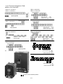
5000VG7S Series
INSTRUCTION MANUAL
High-Performance, Vector Control Inverter
CT Use (150%)
200V Series
0.75kW/FRN0.75VG7S-2
∼90kW/FRN90VG7S-2
400V Series
3.7kW/FRN3.7VG7S-4
∼400kW/FRN400VG7S-4
VT Use (110%)
200V Series
1.5kW/FRN0.75VG7S-2
∼110kW/FRN90VG7S-2
400V Series
5.5kW/FRN3.7VG7S-4
∼500kW/FRN400VG7S-4
HT Use (200%/170%)
200V Series
3.7kW/FRN3.7VG7S-2
∼55kW/FRN55VG7S-2
400V Series
3.7kW/FRN3.7VG7S-4
∼55kW/FRN55VG7S-4
CAUTION
■ Read all operating instructions
before installing, connecting
(wiring), operating, servicing, or
inspecting the inverter.
■ Ensure that this instruction manual
is made available to the final user
of the inverter.
■ Store this manual in a safe,
convenient location.
■ The product is subject to change
without prior notice.
INR-HF51306 c-E
Instructions
Thank you for purchasing our FRENIC5000VG7S series inverter. This product is used to drive a 3-phase
induction motor at variable speed. As incorrect use of this product may result in personal injury and/or
property damage, read all operating instructions before using.
As this manual does not cover the use of function cords and option cards, etc., refer to FRENIC5000VG7S
Users Manual.
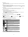
Safety Instructions
Read this manual carefully before installing, connecting (wiring), operating, servicing, or inspecting the inverter.
Familiarize yourself with all safety features before using the inverter.
In this manual, safety messages are classified as follows:
Improper operation may result in serious personal injury or death.
Improper operation may result in slight to medium personal injury or
property damage.
Situations more serious than those covered by CAUTION will depend on prevailing circumstances.
Always follow instructions.
Instructions on use
· This inverter is designed to drive a 3-phase induction motor and is not suitable for a single-phase motor or
others, as fire may result.
· This inverter may not be used (as is) as a component of a life-support system or other medical device
directly affecting the personal welfare of the user.
· This inverter is manufactured under strict quality control standards. However, safety equipment must be
installed if the failure of this device may result in personal injury and/or property damage.
There is a risk of accident.
Instructions on installation
· Mount this inverter on an incombustible material such as metal.
There is a risk of fire.
· Do not place combustible or flammable material near this inverter, as fire may result.
· The inverter housed in IP00 (18.5kW or over) should be installed in a place where no one can touch it
easily.
Electric shock or injury may result.
0-1
· Do not hold or carry this inverter by the surface cover. Inverter may be dropped causing injury.
· Ensure that the inverter and heat sink surfaces are kept free from foreign matter (lint, paper dust, small
chips of wood or metal chips), as fire or accident may result.
· Do not install or operate a damaged inverter or an inverter with missing parts, as injury may result.
· When changing installation bracket position, use the attached screws, as injury may result.
Instructions on wiring
· Confirm that the phases and rated voltage of this product match those of the AC power supply, as injury
may result.
· Do not connect the AC power supply to the output terminals (U, V, and W), as injury may result.
· Do not connect a braking resistor directly to the DC terminals (P(+) and N(-)), as fire may result.
· When using DC power input, ensure that the fan power switching connector (CN RXTX) is correctly
engaged in the inverter as a trouble may occur.
· When using DC power input of 18.5kW or larger inverter, be sure to connect AC power to terminals R0
and T0 for a power supply of fan as a trouble may occur.
· Ensure that the noise generated by the inverter, motor, or wiring does not adversely affect peripheral
sensors and equipment, as accident may result.
0-2
Instructions on operation
· Be sure to install the surface cover before turning on the power (closed). Do not remove the cover while
power to the inverter is turned on.
Electric shock may occur.
· Do not operate switches with wet hands, as electric shock may result.
· When the retry function is selected, the inverter may restart automatically after tripping. (Design the
machine to ensure personal safety in the event of restart)
Accident may result.
· When the torque limiting function is selected, operating conditions may differ from preset conditions
(acceleration/deceleration time or speed). In this case, personal safety must be assured.
Accident may result.
· As the STOP key is effective only when a function setting has been established, install an emergency
switch independently, and when an operation via the external signal terminal is selected, the STOP key
on the KEYPAD panel will be disabled.
Accident may result.
· As operations start suddenly if alarm is reset with a running signal input, confirm that no running signal is
input before resetting alarm.
Accident may result.
· When an alarm is activated, the motor coasts. If the motor needs to be stopped in such a case, install a
brake to the machine with the motor.
Accident may result.
· If AUTO RESTART is selected in the restart mode after momentary power failure (function code F14), the
inverter restarts automatically starting the motor rotation when the power is recovered.
Accident may result.
· When the tuning (function code H01) is started, the motor, machine or equipment starts and stops
repeatedly. Ensure safety before performing tuning.
Accident may result.
· If the user set the function codes wrongly or without completely understanding this user’s manual, the
motor may rotate with a torque or at a speed not permitted for the machine.
Accident or injury may result.
· Do not touch inverter terminals when energized even if inverter has stopped.
Electric shock may result.
· Do not start or stop the inverter using the main circuit power.
Failure may result.
· Do not touch the heat sink or braking resistor because they become very hot.
Burns may result.
· As the inverter can set high speed operation easily, carefully check the performance of motor or machine
before changing speed settings.
Injury may result.
· Do not use the inverter braking function for mechanical holding.
Injury may result.
· During pre-excitation, the speed adjuster does not function and the motor may be rotated by load
disturbance. When using pre-excitation, therefore, also use the mechanical brake.
Injury may result.
· If improper data is set at the function code related with speed adjuster as in the case of setting high gain
abruptly, the motor may hunt.
Injury may result.
0-3
Instructions on maintenance, inspection, and replacement
· Wait a minimum of five minutes (15kW or less) or ten minutes (18.5kW or more) after power has been
turned off (open) before starting inspection. (Also confirm that the charge lamp is off and that DC voltage
between terminals P(+) and N(-) does not exceed 25V.)
Electric shock may result.
· Only authorized personnel should perform maintenance, inspection, and replacement operations.
(Take off metal jewelry, such as watches and rings. Use insulated tools.)
Electric shock or injury may result.
Instructions on disposal
· Treat as industrial waste when disposing it.
Injury may result.
Other instructions
· Never modify the product.
Electric shock or injury may result.
General Instructions
Although figures in this manual may show the inverter with covers and safety screens removed for
explanation purposes, do not operate the device until all such covers and screens have been replaced.
0-4
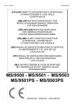
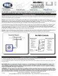
Warning Label Position
Inverter with a small capacity (15kW or lower)
Inverter with a middle capacity (18.5kW or higher)
0-5
Warning Label Position for Inside the Inverter
0-6
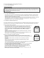
Compliance with UL/cUL Standards
1. Overview
The UL standard is an abbreviation for Underwriters Laboratories Inc. and is a safety standard for preventing
fires and other accidents, and protecting users, servicemen, and general people in the United States.
The cUL standard is a standard which the UL constituted to meet the CSA standard. Products approved by
the cUL standard are as valid as produces approved by the CSA standard.
2. Notes
See the following notes when you use your inverters as UL/cUL approved products.
CAUTION for UL/cUL requirements
・Hazard of electrical shock. Disconnect incoming power before working on this control.
・Dangerous voltage exists until charge lights is off.
・More than one live circuit.
・Use 60/75℃ or 90℃ copper wire only.
・A Class 2 circuit wired with class1 wire.
・Field wiring connection must be made by a UL Listed and CSA Certified closed-loop terminal
connector sized for the wire gauge involved. connector must be fixed using the crimp tool
specified by the connector manufacturer.
・Connect the power supply to main power supply terminals via the Molded-case circuit
breaker(MCCB) or the earth leakage circuit breaker(ELCB) to apply the UL Listing Mark.
(See Instruction Manual basic connection diagram Fig.2-3-1).
・In case of using auxiliary control-power input (R0,T0), connect it referring to Instruction Manual Basic
connection diagram Fig.2-3-1.
・Solid state motor overload protection is provided in each model.
See Users Manual : MHT263□ for details.
0-7
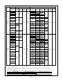
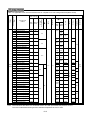
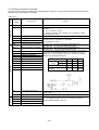
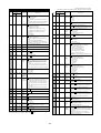
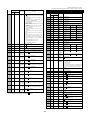
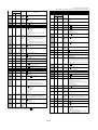
Tightening torque and wire range
1. 60℃/75℃ copper wire
CT/HT Use
Inverter type
Voltage
FRN□
VG7S-2/4
0.75
1.5
2.2
3.7
5.5
7.5
11
15
18.5
3Phase
200V
Required torque [lb-inch](N.m)
Auxiliary
Main
Ground control- Control
terminal
power
31.0
(3.5)
31.0
(3.5)
51.3
(5.8)
51.3
(5.8)
22
30
37
45
239
(27)
6.2
(0.7)
119
(13.5)
55
75
90
3.7
5.5
7.5
11
15
18.5
425
(48)
239
(27)
31.0
(3.5)
31.0
(3.5)
51.3
(5.8)
51.3
(5.8)
22
30
37
45
119
(13.5)
55
119
(13.5)
75
3Phase
400V
90
239
(27)
10.6
(1.2)
110
132
160
200
220
280
315
355
400
239
(27)
425
(48)
L1/R,L2/S,
L3/T
14
(2.1)
12 (3.3)
8 (8.4)
6 (13.3)
8X2 (8.4X2)
6X2 (13.3X2)
4X2 (21.2X2)
10.6
(1.2)
119
(13.5)
Wire range [AWG] (mm2)
6.2
(0.7)
3X2
(26.7X2)
2X2
(33.6X2)
1X2
(42.4X2)
2/0X2
(67.4X2)
3/0X2
(85X2)
2/0X2
(67.4x2)
600
(304)
12 (3.3)
10 (5.3)
8 (8.4)
6 (13.3)
4 (21.2)
3 (26.7)
6X2
(13.3X2)
2 (33.6)
1 (42.4)
3X2
(26.7X2)
2X2
(33.6X2)
2/0
(67.4)
3/0
(85)
1X2
(42.4X2)
350
(177)
3/0X2
(85X2)
4/0X2
(107.2X2)
250X2
(127X2)
400X2
(203X2)
250X3
(127X3)
600X2
(304X2)
350X3
(177X3)
0-8
U,V,W
14
(2.1)
Auxiliary
P1,P(+) P(+),DB, controlN(-)
power
14
(2.1)
14
10 (5.3)
10
(2.1)
(5.3)
8 (8.4)
6 (13.3)
6 (13.3)
4 (21.2)
4 (21.2)
3 (26.7)
12 (3.3)
3
6X2
(26.7)
(13.3X2)
10
(5.3)
4X2
4X2
(21.2X2) (21.2X2)
1/0
3X2
8
(53.5)
(26.7X2)
(8.4)
3/0
4/0
(85)
(107.2)
6
(13.3)
4/0
1X2
(107.2)
(42.4X2)
1/0X2
2/0X2
4
(53.5X2) (67.4X2)
(21.2)
3/0X2
4/0X2
2
(85X2)
(107.2X2) (33.6)
4/0X2
250X2
1
(107.2X2) (127X2)
(42.4)
14 (2.1)
14
(2.1)
12 (3.3)
10 (5.3)
10
(5.3)
14
8
(2.1)
(8.4)
6
(13.3)
6(13.3)
4 (21.2)
3 (26.7)
2
(33.6)
1/0
(53.5)
3/0
(85)
4/0
(107.2)
1/0X2
(53.5X2)
400
(203)
3/0X2
(85X2)
250X2
(127X2)
300X2
(152X2)
400X2
(203X2)
250X3
(127X3)
600X2
(304X2)
350X3
(177X3)
Control
16
(1.3)
24
(0.2)
16
(1.3)
24
(0.2)
4 (21.2)
3 (26.7) 12(3.3)
2 (33.6)
10
1
(5.3)
(42.4)
3X2
8
(26.7X2)
(8.4)
4/0
(107.2)
6
(13.3)
1X2
(42.4X2)
1/0X2
4
(53.5X2) (21.2)
3/0X2
3
(85X2)
(26.7)
4/0X2
2
(107.2x2) (33.6)
300X2
1/0
(152X2)
(53.5)
350X2
2/0
(177X2)
(67.4)
250X3
(127X3)
3/0
(85)
300X3
(152X3)
400X3
(203X3)
250
(127)
500X3
(253X3)
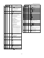
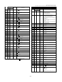
VT Use
Inverter type
Voltage
FRN□
VG7S-2/4
0.75
1.5
2.2
3.7
5.5
Required torque [lb-inch](N.m)
Auxiliary
Main
Ground control- Control
terminal
power
31.0
(3.5)
31.0
(3.5)
51.3
(5.8)
51.3
(5.8)
11
3Phase
200V
18.5
22
30
45
3X2
(26.7X2)
10.6
(1.2)
6.2
(0.7)
10.6
(1.2)
6.2
(0.7)
119
(13.5)
37
239
(27)
119
(13.5)
55
75
90
3.7
5.5
7.5
11
15
18.5
22
30
37
45
425
(48)
239
(27)
31.0
(3.5)
31.0
(3.5)
51.3
(5.8)
51.3
(5.8)
119
(13.5)
55
119
(13.5)
75
3Phase
400V
90
239
(27)
110
132
160
200
220
280
239
(27)
425
(48)
315
355
400
L1/R,L2/S,
L3/T
14 (2.1)
12 (3.3)
8 (8.4)
6 (13.3)
8X2 (8.4X2)
6X2
(13.3X2)
4X2 (21.2X2)
7.5
15
Wire range [AWG] (mm2)
3X2
(26.7X2)
1X2
(42.4X2)
2/0X2
(67.4X2)
3/0X2
(85X2)
2/0X2
(67.4X2)
4/0
(107.2X2)
250X2
(127X2)
10 (5.3)
8 (8.4)
6 (13.3)
4 (21.2)
3 (26.7)
6X2
(13.3X2)
1 (42.4)
3X2(26.7X2)
2X2
(33.6X2)
3X2
(26.7X2)
3/0
(85)
1X2
(42.4X2)
1/0X2
(53.5X2)
3/0X2
(85X2)
4/0X2
(107.2X2)
250X2
(127X2)
350X2
(177X2)
4/0X3
(107.2X3)
300X3
(152X3)
350X3
(177X3)
500X3
(253X3)
U,V,W
14
(2.1)
10 (5.3)
8 (8.4)
6 (13.3)
8X2
(8.4X2)
3 (26.7)
6X2
(13.3X2)
4X2
(21.2X2)
3X2
(26.7X2)
2X2
(33.6X2)
4/0
(107.2)
1/0X2
(53.5X2)
3/0X2
(85X2)
4/0X2
(107.2X2)
300X2
(152X2)
12 (3.3)
10 (5.3)
8
(8.4)
6 (13.3)
4 (21.2)
3 (26.7)
2
(33.6)
1/0
(53.5)
2X2
(33.6X2)
4/0
(107.2)
1/0X2
(53.5X2)
2/0X2
(67.4X2)
3/0X2
(85X2)
250X2
(127X2)
300X2
(152X2)
400X2
(203X2)
250X3
(127X3)
300X3
(152X3)
350X3
(177X3)
600X3
(304X3)
P1,P(+)
P(+),DB,
N(-)
14
(2.1)
10
14
(5.3)
(2.1)
6 (13.3)
10X2
(5.3X2)
3 (26.7) 12 (3.3)
6X2
(13.3X2)
10
(5.3)
4X2
(21.2X2)
3X2
8
(8.4)
(26.7X2)
2X2
(33.6X2)
6
(13.3)
1X2
(42.4X2)
2/0X2
4
(67.4X2)
(21.2)
4/0X2
2
(107.2X2) (33.6)
250X2
(127X2)
1
(42.4)
350X2
(177X2)
14 (2.1)
10
(5.3)
14
(2.1)
6
(13.3)
4 (21.2)
3 (26.7) 12 (3.3)
2 (33.6)
10
(5.3)
1 (42.4)
3X2
8
(8.4)
(26.7X2)
2X2
(33.6X2)
6
(13.3)
1X2
(42.4X2)
1/0X2
4
(53.5X2)
(21.2)
3/0X2
3
(85X2)
(26.7)
4/0X2
2
(107.2X2) (33.6)
300X2
1/0
(152X2)
(53.5)
350X2
2/0
(177X2)
(67.4)
500X2
(253X2)
3/0
(85)
300X3
(152X3)
400X3
(203X3)
500X3
250
(127)
(253X3)
600X3
(304X3)
Auxiliary
controlpower
Control
16
(1.3)
24
(0.2)
16
(1.3)
24
(0.2)
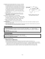
・“Suitable for use on a circuit capable or delivering not more than 42,000 rms symmetrical amperes, 230V maximum”
rated for 200V class input.
・“Suitable for use on a circuit capable or delivering not more than 42,000 rms symmetrical amperes, 480V maximum”
rated for 400V class input.
Connect power supplies described in the following table as the input power supply for your inverters. (short circuit standard)
Inverter model
Maximum input voltage
Input power supply current
FRN0.75VG7S-2 - FRN90VG7S-2
AC230V
42,000A or less
FRN3.7VG7S-4 - FRN400VG7S-4
AC480V
0-9
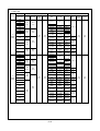
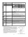
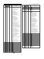
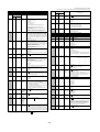
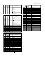
2. 90℃ copper wire
CT/HT Use
Inverter type
Voltage
FRN□
VG7S-2/4
0.75
1.5
2.2
3.7
5.5
7.5
11
15
18.5
3Phase
200V
Required torque [lb-inch](N.m)
Auxiliary
Main
Ground control- Control
terminal
power
51.3
(5.8)
31.0
(3.5)
51.3
(5.8)
10.6
(1.2)
119
(13.5)
37
45
239
(27)
6.2
(0.7)
119
(13.5)
55
75
90
3.7
5.5
7.5
11
15
18.5
22
30
37
45
425
(48)
239
(27)
31.0
(3.5)
31.0
(3.5)
51.3
(5.8)
51.3
(5.8)
119
(13.5)
55
90
119
(13.5)
239
(27)
10.6
(1.2)
110
132
160
200
239
(27)
220
280
315
355
400
425
(48)
10 (5.3)
8 (8.4)
6 (13.3)
3 (26.7)
6X2
(13.3X2)
4X2
(21.2X2)
3X2
(26.7X2)
4/0
(107.2)
1/0X2
(53.5X2)
2/0X2
(67.4X2)
350
(177)
500
(253)
14 (2.1)
12 (3.3)
10 (5.3)
8 (8.4)
6 (13.3)
75
3Phase
400V
L1/R,L2/S,
L3/T
14 (2.1)
31.0
(3.5)
22
30
Wire range [AWG] (mm2)
6.2
(0.7)
U,V,W
Auxiliary
P1,P(+) P(+),DB, controlN(-)
power
14 (2.1)
14 (2.1)
10 (5.3)
8 (8.4)
6 (13.3)
4 (21.2)
6X2
(13.3X2)
1
(42.4)
2/0
(67.4)
3/0
(85)
1X2
(42.4X2)
400
(203)
600
(304)
14 (2.1)
10 (5.3)
8 (8.4)
4 (21.2)
3 (26.7)
2 (33.6)
1/0 (53.5)
4X2
(21.2X2)
1/0 (53.5)
4 (21.2)
2 (33.6)
1
(42.4)
2/0 (67.4)
3/0 (85)
3/0 (85)
4/0
(107.2)
250 (127)
400
(203)
600
(304)
4/0X2
(107.2X2)
300X2
(152X2)
350X2
(177X2)
500X2
(253X2)
600X2
(304X2)
1X2
(42.4X2)
300 (152)
400
(203)
600
(304)
4/0X2
(107.2X2)
350X2
(177X2)
400X2
(203X2)
500X2
(253X2)
600X2
(304X2)
0-10
6 (13.3)
12 (3.3)
8 (8.4) 14 (2.1)
6 (13.3)
4 (21.2)
3 (26.7)
6X2
(13.3X2)
1/0
10
(53.5)
(5.3)
3/0
(85)
8
(8.4)
4/0
(107.2)
1/0X2
6
(53.5X2) (13.3)
3/0X2
4
(85X2)
(21.2)
4/0X2
2
(107.2X2) (33.6)
Control
16
(1.3)
24
(0.2)
16
(1.3)
24
(0.2)
14 (2.1)
12 (3.3)
8 (8.4)
14 (2.1)
6 (13.3)
4 (21.2)
3 (26.7)
2 (33.6) 12 (3.3)
1/0
10
(53.5)
(5.3)
3/0 (85)
8
4/0
(8.4)
(107.2)
1X2
6
(42.4X2) (13.3)
400(203)
4
3/0X2
(21.2)
(85X2)
250X2
1
(127X2)
(42.4)
300X2
1/0
(152X2)
(53.5)
400X2
(203X2)
2/0
(67.4)
500X2
(253X2)
300X3
(152X3)
4/0
(107.2)
400X3
(203X3)
VT Use
Inverter type
Voltage
FRN□
VG7S-2/4
0.75
1.5
2.2
3.7
5.5
Required torque [lb-inch](N.m)
Auxiliary
Main
Ground control- Control
terminal
power
18.5
3Phase
200V
31.0
(3.5)
31.0
(3.5)
51.3
(5.8)
51.3
(5.8)
10.6
(1.2)
22
30
119
(13.5)
37
45
239
(27)
6.2
(0.7)
119
(13.5)
55
75
90
3.7
5.5
7.5
11
15
18.5
22
30
37
45
425
(48)
239
(27)
31.0
(3.5)
31.0
(3.5)
51.3
(5.8)
119
(13.5)
55
90
119
(13.5)
239
(27)
10.6
(1.2)
110
132
160
200
220
280
239
(27)
425
(48)
315
355
400
10 (5.3)
8 (8.4)
6 (13.3)
8X2
(8.4X2)
6X2
(13.3X2)
4X2
(21.2X2)
3X2
(26.7X2)
2X2
(33.6X2)
1/0X2
(53.5X2)
2/0X2
(67.4X2)
1/0X2
(53.5X2)
3/0X2
(85X2)
4/0X2
(107.2X2)
12 (3.3)
10 (5.3)
8 (8.4)
6 (13.3)
51.3
(5.8)
75
3Phase
400V
L1/R,L2/S,
L3/T
14 (2.1)
7.5
11
15
Wire range [AWG] (mm2)
6.2
(0.7)
4 (21.2)
3 (26.7)
2 (33.6)
1/0 (53.5)
4X2
(21.2X2)
1/0
(53.5)
3/0
(85)
4/0
(107.2)
1X2
(42.4X2)
400
(203)
3/0X2
(85X2)
4/0X2
(107.2X2)
300X2
(152X2)
350X2
(177X2)
4/0X3
(107.2X3)
600X2
(304X2)
400X3
(203X3)
U,V,W
P1,P(+)
14 (2.1)
14 (2.1)
10 (5.3)
8 (8.4)
6
(13.3)
4
(21.2)
12 (3.3)
8 (8.4)
6
(13.3)
4 (21.2)
3 (26.7)
6X2
(13.3X2)
6X2
(13.3X2)
4X2
(21.2X2)
4x2
3X2
(21.2x2) (26.7X2)
3/0
4/0
(85)
(107.2)
1x2
1/0X2
(42.4x2) (53.5X2)
2/0X2
3/0X2
(67.4X2)
(85X2)
3/0X2
4/0X2
(85X2)
(107.2)
4/0X2
300X2
(107.2X2) (152X2)
14 (2.1)
10 (5.3)
Auxiliary
controlpower
Control
16
(1.3)
24
(0.2)
16
(1.3)
24
(0.2)
14
(2.1)
10
(5.3)
8
(8.4)
6
(13.3)
4
(21.2)
2
(33.6)
14 (2.1)
12 (3.3)
8 (8.4)
8 (8.4)
P(+),DB,
N(-)
6 (13.3)
4 (21.2)
4 (21.2)
3 (26.7)
2 (33.6)
2 (33.6)
1
1/0
(42.4)
(53.5)
4X2
3X2
(21.2X2) (26.7X2)
3/0
4/0
(85)
(107.2)
1X2
1X2
(42.4X2) (42.4X2)
2/0X2
1/0X2
(53.5X2) (67.4X2)
400
3/0X2
(203)
(85X2)
250X2
(127X2)
4/0X2
(107.2X2) 300X2
(152X2)
400X2
350X2
(177X2)
(203X2)
400X2
250X3
(203X2)
(127X3)
250X3
300X3
(127X3)
(152X3)
600X2
400X3
(304X2)
(203X3)
500X3
600X3
(253X3)
(304X3)
14
(2.1)
6 (13.3)
12 (3.3)
10
(5.3)
8
(8.4)
6
(13.3)
4
(21.2)
1
(42.4)
1/0
(53.5)
2/0
(67.4)
4/0
(107.2)
・“Suitable for use on a circuit capable or delivering not more than 42,000 rms symmetrical amperes, 230V maximum”
rated for 200V class input.
・“Suitable for use on a circuit capable or delivering not more than 42,000 rms symmetrical amperes, 480V maximum”
rated for 400V class input.
Connect power supplies described in the following table as the input power supply for your inverters. (short circuit standard)
Inverter model
FRN0.75VG7S-2 - FRN90VG7S-2
FRN3.7VG7S-4 - FRN400VG7S-4
Maximum input voltage
AC230V
AC480V
0-11
Input power supply current
42,000A or less
Compliance with European Standard
The CE marking presented on Fuji products is related to the Council Directive 89/336/EEC and the Low
Voltage Directive 73/23/EEC for the Electromagnetic Compatibility (EMC) in Europe.
Compliant standards
・EN 61800-3: 1997
・EN 50178: 1997
Only the models in the 400V series comply with the standards above among the "FRENIC5000 VG7S" series.
The 200V series do not conform to the standards. Please note that products of the CT/HT use 18.5 kW and
the VT use 22 kW do not comply with the standards, and if you need to use compliant products, you should
use the products of the CT/HT use 22 kW and the VT use 30 kW which are models with larger capacities by
one grade.
1. Compliance with Low Voltage Directive
1-1 Overview
Inverters are subject to the Low Voltage Directive in Europe. Fuji has obtained an approval for the compliance
from a European inspection organization, and voluntarily declares the compliance with the Low Voltage
Directive.
1-2 Notes
See the notes below when you use the inverters in your products compliant with the Low Voltage Directive in
Europe.
・ The contact capacity for the alarm relay output (30A, B, C) and the relay signal output (Y5A, Y5C) is DC
48V, 0.5A.
・ Connect your inverter to the ground securely.
・ Connect a ring terminal to a wire when you attach it to the main circuit and inverter ground terminals.
・ Use an independent wiring for the inverter ground terminal G. (Do not connect two or more wires)
・ When you use an earth leakage breaker (RCD), you can use only the Type B for protection for the power
supply.
Also you should use a transformer for double insulation or reinforced insulation to insulate your inverter
from the power supply.
・ Use a molded case circuit breaker (MCCB) and a magnetic contactor (MC) compliant with the EN or IEC
standard.
・ For a power supply system (I-T NET) where a neutral point is not grounded, the control terminals are
provided as basic insulation in respect to the main circuit. When a person may touch them directly, you
should add an external insulation circuit for double insulation.
・ Use your inverter under a condition corresponding to the overvoltage category III and the pollution degree 2
or more prescribed in the IEC664. Install your inverter in a control panel (IP54 or more) with a structure
preventing water, oil, carbon and dusts from entering for meeting the pollution degree 2 or more.
・ Use a wire with the diameter and the type prescribed in the Appendix C of the EN 60204 for the
input/output wiring for your inverter.
・ When you install an external heatsink which is a heatsink for inverter external to the control panel, you
should install a protection cover preventing a capacitor and a breaking resistor installed on the heatsink
from being touched.
・ When you install an optional AC reactor, a DC reactor, and an external braking resistor, follow the
description below to prevent an electric shock due to touching the terminals and active electrical parts.
1) Install them in a casing or wall of the IP4X when a person may have an easy access to them.
2) Install them in a casing or wall of the IP2X when a person does not have an easy access to them.
0-12
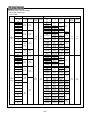
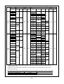
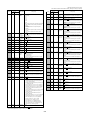
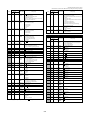
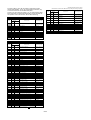
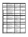
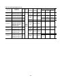
Table 1-2 Applicable main circuit motor/wire size for compliance to Low Voltage Directive(400V series)
3.7 3.7VG7S-4(CT/HT)
10
15
5.5 3.7VG7S-4(VT)
15
20
20
30
30
40
40
50
3.5
11 11VG7S-4(CT/HT)
15 11VG7S-4(VT)
15 15VG7S-4(CT/HT)
18.5 15VG7S-4(VT)
5.8
10
(10)
6
6
6
(6)
16
(16)
10
10
25
(16)
75
100
16
(16)
16X2
(16)
25
25
100
125
25
(16)
50
(25)
35
35
100
150
35
(25)
25X2
(25)
50
50
125
175
50
(25)
35X2
(35)
25X2
25X2
175
-
25X2
-
35X2
35X2
95
95
13.5
55 55VG7S-4(CT/HT)
75 55VG7S-4(VT)
400V
series
75 75VG7S-4(CT)
90 75VG7S-4(VT)
13.5
200
-
225
-
300
-
90 90VG7S-4(CT)
110 90VG7S-4(VT)
27
110 110VG7S-4(CT)
132 110VG7S-4(VT)
-
50X2
70X2
70X2
-
70X2
150X2
-
150X2
185X2
185X2
(185)
-
240X2
240X2
-
240X2
(240)
-
240X2
185X3
800
-
240X2
(240)
-
150X3
185X3
1,000
-
185X3
(300)
-
185X3
240X3
1,200
-
240X3
-
300X3
300X3
500
-
600
-
700
27
48
400 400VG7S-4(CT)
500 400VG7S-4(VT)
50X2
(50)
120X2
-
355 355VG7S-4(CT)
400 355VG7S-4(VT)
50X2
240
(120)
315 315VG7S-4(CT)
355 315VG7S-4(VT)
35X2
-
400
280 280VG7S-4(CT)
315 280VG7S-4(VT)
-
95X2
-
220 220VG7S-4(CT)
280 220VG7S-4(VT)
95
(50)
-
350
200 200VG7S-4(CT)
220 200VG7S-4(VT)
0.7
185
160 160VG7S-4(CT)
200 160VG7S-4(VT)
1.2
70(35)
2.5 95X2
to
240
6 120X2
132 132VG7S-4(CT)
160 132VG7S-4(VT)
120X2
(120)
240
4
6
10
16
25
50
300X2
70
Note: The used wires are 600V PVC insulated electric wire with permissible temperature of 70°C.
This wire is selected assuming that the ambient temperature is 50°C or less.
0-13
Controller
P(+),DB,N(-)
2.5
10
45 45VG7S-4(CT/HT)
55 45VG7S-4(VT)
P1,P(+)
4
(4)
60
37 37VG7S-4(CT/HT)
45 37VG7S-4(VT)
4
(4)
40
30 30VG7S-4(CT/HT)
37 30VG7S-4(VT)
2.5
4
(4)
22 22VG7S-4(CT/HT)
30 22VG7S-4(VT)
2.5
6
(6)
7.5 7.5VG7S-4(CT/HT)
11 7.5VG7S-4(VT)
2.5
R0,T0
With Without
DCR DCR
U,V,W
Controller
L1/R,L2/SL3/T
( G)
2.5
(2.5)
5.5 5.5VG7S-4(CT/HT)
7.5 5.5VG7S-4(VT)
R0,T0
With Without
DCR DCR
G
Inverter type
FRN□
Recommended wire size [mm2]
Tightening torque [N.m]
L1/R,L2/S,L3/T
U,V,W
P1,P(+),DB,N(-)
Applicable motor
KW
Voltage
Fuse/MCCB
Rated current [A]
0.2
~
0.75
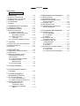
Contents
Instructions
Safety Instructionss
1. Before Use
・・・・・・・・・・・・・・・・・・・・・・ 1-1
1-1 Inspection After Receipt ・・・・・・・・・・・・ 1-1
1-2 External View of the Product ・・・・・・・・ 1-1
1-3 Handling of the Product ・・・・・・・・・・・・ 1-2
1-4 Transportation ・・・・・・・・・・・・・・・・・・・・ 1-3
1-5 Storage ・・・・・・・・・・・・・・・・・・・・・・・・・・ 1-3
2. Installation and Connection
・・・・・ 2-1
2-1 Operating Conditions ・・・・・・・・・・・・・・ 2-1
2-2 Installation Procedure ・・・・・・・・・・・・・・ 2-2
2-3 Electric Connections ・・・・・・・・・・・・・・・ 2-4
2-3-1 Basic Connections ・・・・・・・・・・・ 2-4
2-3-2 Wiring of Main Circuit and
Grounding Terminals ・・・・・・・・・ 2-6
2-3-3 Wiring of Control
Terminals ・・・・・・・・・・・・・・・・・・・ 2-13
2-3-4 Terminal Arrangement Chart
・・ 2-17
3. Test Run
・・・・・・・・・・・・・・・・・・・・・・・・ 3-1
3-1 Preliminary Check and Preparation ・・ 3-1
3-2 Operating Methods ・・・・・・・・・・・・・・・・ 3-1
3-3 Test Run ・・・・・・・・・・・・・・・・・・・・・・・・・ 3-1
4. KEYPAD Panel
・・・・・・・・・・・・・・・・・・ 4-1
4-1 Appearance of KEYPAD Panel ・・・・・・ 4-1
4-2 Alarm Mode ・・・・・・・・・・・・・・・・・・・・・・ 4-3
4-3 KEYPAD Operation System
(Hierarchical Structure of
LCD Screens) ・・・・・・・・・・・・・・・・・・・・ 4-4
4-3-1 During Normal Operation
・・・・・ 4-4
4-3-2 When an Alarm
Raised Occurs ・・・・・・・・・・・・・・・ 4-4
4-3-3 Program Mode
・・・・・・・・・・・・・・ 4-6
5. Function Selection
・・・・・・・・・・・・・・
8. Maintenance and Inspection
・・・・ 8-1
8-1 Daily Inspection ・・・・・・・・・・・・・・・・・・・ 8-1
8-2 Periodical Inspection
・・・・・・・・・・・・・・ 8-1
8-3 Measurement of Main Circuit
Electrical Quantity ・・・・・・・・・・・・・・・・・ 8-4
8-4 Insulation Test ・・・・・・・・・・・・・・・・・・・・ 8-5
8-5 Parts Replacement ・・・・・・・・・・・・・・・・ 8-5
8-6 Inquiries about Products and
Product Guarantee ・・・・・・・・・・・・・・・・ 8-5
9. Compliance with Standards
・・・・ 9-1
9-1 Compliance with
UL/cUL Standards ・・・・・・・・・・・・・・・・ 9-1
9-1-1 Overview ・・・・・・・・・・・・・・・・・・・ 9-1
9-1-2 Notes ・・・・・・・・・・・・・・・・・・・・・・ 9-1
9-2 Compliance with
European Standard ・・・・・・・・・・・・・・・ 9-1
9-3 Compliance with Low
Voltage Directive ・・・・・・・・・・・・・・・・・ 9-1
9-3-1 Overview ・・・・・・・・・・・・・・・・・・・ 9-1
9-3-2 Notes ・・・・・・・・・・・・・・・・・・・・・・ 9-1
9-4 Compliance with EMC standard ・・・・・ 9-1
9-4-1 Overview ・・・・・・・・・・・・・・・・・・・ 9-1
9-4-2 RFI Filter ・・・・・・・・・・・・・・・・・・・ 9-1
9-4-3 Recommended Installation ・・・・ 9-1
5-1
6. List of Inverter Protective
Functions ・・・・・・・・・・・・・・・・・・・・・・・ 6-1
7. Function Description
(Arranged by Function)
・・・・・・・・・・ 7-1
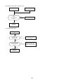
7-1 If You Think Defective
・・・・・・・・・・・・・ 7-1
7-1-1 If You Think Defective ・・・・・・・・・ 7-1
7-1-2 What You Should Check First ・・ 7-1
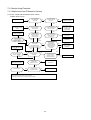
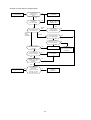
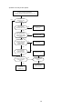
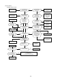
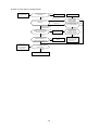
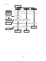
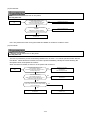
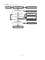
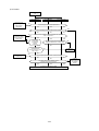
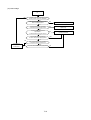
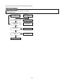
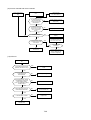
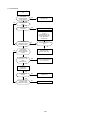
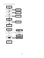
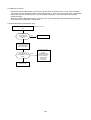
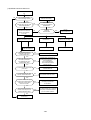
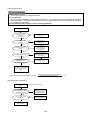
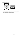
7-2 Checks Using Flowchart
・・・・・・・・・・・ 7-3
7-2-1 Malfunctions not
Followed by Alarms ・・・・・・・・・・・ 7-3
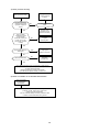
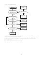
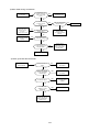
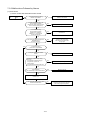
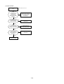
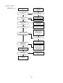
7-2-2 Malfunctions Followed
Alarms ・・・・・・・・・・・・・・・・・・・・・・ 7-11
0-14
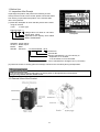
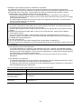
1. Before Use
1-1 Inspection After Receipt
Unpackage the product and perform the following checks.
If the product is found to have a fault, please contact the dealer
from which you purchased the product or the nearest sales
office of Fuji Electric.
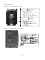
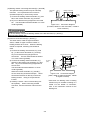
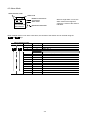
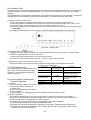
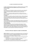
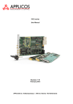
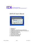
(1) Read the nameplate to check that the product is the same
thing as ordered.
TYPE
: Inverter type
FRN 30 VG7S - 4
Voltage class: 2 for 200V or 4 for 400V
Series name: VG7S
Applicable motor capacity: 30 for 30kW
Model :FRENIC5000
Nameplate
SOURCE : Power ratings
OUTPUT : Rated output
MASS
: Mass
SER.No. : Serial No. 4 3 HH12345R678 - 001H
Product No.
Serial lot No.
Month of manufacture:1 to 9 for January to
September, X for October,
Y for November,or Z for December
Year of manufacture:Last digit of A.D. (4 for 2004)
(2) Check for broken or missing parts and damage caused to the cover/body during transportation.
· Do not energize a product with broken or missing parts or damaged during transportation.
Doing so may lead to electric shock or fire.
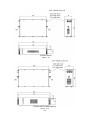
1-2 External View of the Product
1-1
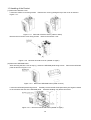
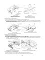
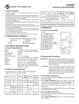
1-3 Handling of the Product
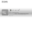
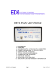
(1) Removal of Surface Cover
Loosen the surface cover fixing screws. Remove the cover by pulling the top of the cover as shown in
Figure 1-3-1.
Figure 1-3-1 Removal of Surface Cover (15kW or lower)
Remove the six surface cover fixing screws. Remove the surface cover.
Figure 1-3-2 Removal of Surface Cover (18.5kW or higher)
(2) Removal of KEYPAD Panel
After removing the face cover in step (1), loosen the KEYPAD panel fixing screws. Remove the KEYPAD
panel as shown in Figure 1-3-3.
Figure 1-3-3 Removal of KEYPAD Panel (15kW or lower)
Loosen the KEYPAD panel fixing screws. Carefully remove the KEYPAD panel with your fingers inserted
to the cutouts at the side of the KEYPAD panel. Careless handling may break connectors.
Figure 1-3-4 Removal of KEYPAD Panel (18.5kW or higher)
1-2
1-4 Transportation
Always hold the body during transportation.
Do not hold the cover or any other part. Doing so may break or fall the product.
When using a hoist or crane to transport a product with lifting holes, hang hooks and ropes to the holes.
1-5 Storage
Temporary Storage
Store the product under the conditions specified on Table 1-5-1.
Table 1-5-1
Storage Conditions
Item
Requirement
Ambient temperature
Storage temperature
See Note 1
Relative humidity
Atmosphere
-10 to +50°C
-25 to +65°C
No condensation or freezing should occur
due to sudden temperature changes.
5% to 95% See Note 2
The product should not be exposed to dust, direct sunlight, corrosive or
combustible gas, oil mist, vapor, waterdrops, vibration, or air containing
much salt.
Note 1: The storage temperature applies to the temporary storage during transportation, for example.
Note 2: Do not store the product in a place where the temperature significantly changes as this may cause
condensation or freezing even if the humidity requirement is satisfied.
(1) Do not place the product directly on the floor.
(2) Pack the product with a plastic sheet or such if stored under undesirable conditions.
(3) Seal in a desiccative such as silica gel when packing the product if it may be affected by moisture.
Extended Storage
The requirements to be satisfied when storing the product for an extended period after purchased greatly
depend on the environment. General requirements are listed below.
(1) Satisfy the requirements for temporary storage.
If the storage period exceeds three months, the ambient temperature should be kept below 30 °C to protect
the dead electrolytic capacitor from deterioration.
(2) Carefully pack the product to prevent the intrusion of moisture, etc. Seal in a desiccant to keep the relative
humidity inside the pack below 70%, as a guide.
(3) The product will be often exposed to moisture or dust if left mounted on a unit or console, especially in a
building under construction. In such a case, remove the product and relocate in a well-conditioned place.
The electrolytic capacitor will be deteriorated if left dead for an extended period. Do not leave it dead for a
period exceeding a year.
1-3
2. Installation and Connection
2-1 Operating Conditions
Install the product under the conditions specified in Table 2-1-1.
Table 2-1-1 Operating Conditions
Item
Requirement
Place
Indoor
Ambient
-10 to +50°C
temperature
Relative humidity 5% to 95% (no condensation allowed)
Atmosphere
The product should not be exposed to dust, direct
sunlight, corrosive gas, oil mist, vapor, waterdrops, or
air containing much salt.
No condensation should occur due to sudden
temperature changes.
Altitude
1,000m or less (if more than 1,000m, see Table 2-12)
Vibration
2 to 9Hz: 3mm amplitude
9 to 20Hz: 9.8m/s2 (or 2m/s2 for 200V, 75kW or
higher and 400V, 90kW or higher inverters)
20 to 55Hz: 2m/s2
55 to 200Hz: 1m/s2
Table 2-1-2 Output Reduction Rates at Higher Altitudes
Altitude
Output Current Reduction Rate
1,000m or less
1.00
1,000-1,500m
0.97
1,500-2,000m
0.95
2,000-2,500m
0.91
2,500-3,000m
0.88
2-1
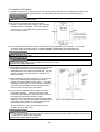
2-2 Installation Procedure
(1) Install the product onto a rigid structure in the vertical direction with the letters, FRENIC5000 VG7S, seen
from the front and fix with specified bolts. Do not install upside down or in the horizontal direction.
Failure to do so may lead to injury.
(2) The inverter generates heat during operation.
Reserve a space as shown in Figure 2-2-1 to ensure
a sufficient flow of cooling air. The heat is radiated
from the top. Do not install the inverter under any
unit susceptible to heat.
Figure 2-2-1
(3) The cooling fins (heat sink) are heated to almost 90°C during operation of the inverter. The inverter
mounting surface should be made of a material capable of withstanding this temperature rise.
The fins may burn your skin.
· Install the inverter onto an incombustible material such as metal.
Failure to do so may lead to fire.
(4) When storing the inverter in a control panel, for example,
sufficiently ventilate the inverter so that its ambient
temperature will not exceed the specified limit. Do not
store the inverter in a small closed box that does not
radiate heat well.
(5) When storing two or more inverters in a unit or control
panel, they are desirably arranged side by side to
minimize the thermal effect on each other. If they are
inevitably arranged with one above another, separating
plate should be provided to prevent the heat transfer
from the bottom side inverter to the above.
(6) The inverter is prepared to be mounted in a control
panel when delivered. It may be externally cooled
using the optional adapter if 15kW or lower or with the
mounting legs relocated if 18.5kW or higher.
With the inverter externally cooled, the heat generated
inside the unit or control panel is dissipated because the
cooling fins, which radiate 70% of the generated heat,
are excluded from the unit or control panel.
Do not exclude the cooling fins where they may be
clogged with lint or damp dust.
Figure 2-2-2 External Cooling System
· Do not admit lint, paper, wooden chips, dust, metallic pieces, and any other foreign matters into the inverter
or allow them to stick to the cooling fins.
Doing so may lead to fire or accident.
2-2
To externally cool a 18.5kW or higher inverter, relocate the upper and lower mounting legs as shown in Figure
2-2-3. Remove the mounting leg fixing screws, relocate the legs, and fix with casing fixing screws. (The
casing fixing screws cannot be directly used for some models. See the following table.)
The mounting leg fixing screws become unnecessary after the legs are relocated.
Voltage
class
200V
400V
Number and Size of Fixing Screws
Mounting leg fixing
Inverter model
screws
FRN18.5VG7S-2~FRN55VG7S-2
5 (M6 ´ 20)
FRN75VG7S-2
7 (M6 ´ 20)
FRN90VG7S-2
6 (M6 ´ 20)
FRN18.5VG7S-4~FRN75VG7S-4
5 (M6 ´ 20)
FRN90VG7S-4~FRN110VG7S-4
7 (M6 ´ 20)
FRN132VG7S-4~FRN160VG7S-4
7 (M6 ´ 20)
FRN200VG7S-4~FRN220VG7S-4
6 (M6 ´ 20)
FRN280VG7S-4~FRN315VG7S-4 Note 3
6 (M8 ´ 20)
FRN355VG7S-4~FRN400VG7S-4 Note 3
8 (M8 ´ 20)
Casing fixing
screws
5 (M5 ´ 16)
5 (M5 ´ 16)
6 (M5 ´ 16)
5 (M5 ´ 16)
5 (M5 ´ 16) Note 1
7 (M5 ´ 16)
6 (M5 ´ 16) Note 1
– Note 2
· Do not use any screws other than specified.
Doing so may lead to fire or accident.
Note 1: Fix the legs with M5 ´ 20 screws.
Note 2: Fix the legs with leg fixing
screws.
Note 3: The lower leg becomes
unnecessary when the inverter is
installed on its bottom.
Figure 2-2-3
· Use the screws provided with the inverter when relocating the mounting legs.
Failure to do so may lead to injury.
2-3
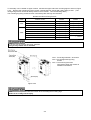
2-3 Electric Connections
Removing the surface cover exposes the terminal blocks. Correctly wire them after reading the following
instructions.
2-3-1 Basic Connections
(1) Connect power supply leads to the main circuit power terminals, L1/R, L2/S, and L3/T. Connecting any
power supply lead to another terminal may fail the inverter. Check that the supply voltage does not exceed
the permissible limit indicated on the nameplate, etc.
(2) The grounding terminal must be grounded to prevent disasters such as electric shock and fire and reduce
the noise.
(3) Use a reliable crimp terminal to connect each lead.
(4) After making connections (wiring), check that:
1) leads are correctly connected,
2) all necessary connections are made, and
3) no terminal or wire is short-circuited or grounded.
(5) When any connection is changed after the inverter is energized:
It takes a long time for the smoothing capacitor in the DC link circuit of the main circuit to be discharged after
the power supply is shut off. After the CHARGE lamp goes off, check with a multimeter or such that the DC
voltage has been reduced to a safe level (25V DC or less). Short-circuiting a circuit in which a voltage
(potential) still remains may generate sparks. Wait until the voltage goes away.
· Always connect the grounding lead.
Failure to do so may lead to electric shock or fire.
· The wiring work should be performed by qualified persons.
· Before working, check that the power supply is shut off (open).
Failure to do so may lead to electric shock.
· Do not use any lead size other than specified.
Doing so may lead to fire.
2-4
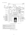
Basic Wiring Diagram
Figure
2-3-1 Basic Wiring Diagram
2-5
2-3-2 Wiring of Main Circuit and Grounding Terminals
Table 2-3-1 Functions of Main Circuit and Grounding Terminals
Terminal symbol
Terminal name
Description
L1/R, L2/S, L3/T
Main circuit power input terminals
Connected with three-phase power source.
U, V, W
Inverter output terminals
Connected with three-phase motor.
R0, T0
Auxiliary control power input terminals Connected with the same AC power source
as used for main circuit, as back-up power
source for control circuit.
P1, P(+)
DC reactor connecting terminals
Connected with (optional) input power-factor
correcting DC reactor.
P(+), DB
Braking resistor connecting terminals
Connected with (optional) braking resistor.
DC link circuit terminals
Supplies DC link circuit voltage.
P(+), N(-)
Connected with (optional) external braking
unit or (optional) power regenerative unit.
Inverter
grounding
terminals
Grounds inverter chassis (casing).
zG
Connected with earth.
(1) Main circuit power input terminals (L1/R, L2/S, and L3/T)
1) The main circuit power input terminals, L1/R, L2/S, and L3/T should be connected with the power source
via earth-leakage circuit breaker for line protection. Any phase may be connected to any lead. If the
zero-phase current is detectable by the upstream system, however, ordinary circuit breakers may be
used.
2) Connect a magnetic contactor so that the inverter can be disconnected from the power source to minimize
the influence of any failure when the inverter protective function is activated.
3) Do not start or stop the inverter by turning the main power switch on or off. Use the control circuit
terminals, FWD and REV, or the FWD, REV, and STOP keys on the KEYPAD panel to start or stop the
inverter. When the inverter is inevitably started or stopped using the main power switch, do not turn it on
or off more than once per hour.
4) Do not connect any terminal to a single-phase power source.
2-6
(2) Inverter output terminals (U, V, and W)
1) Connect three-phase motor leads to the inverter output terminals, U, V, and W with care not to connect a
wrong phase.
2) Do not connect a phase advancing capacitor or surge absorber (suppressor) to the inverter output
terminals.
3) If the wiring between the inverter and the motor is too long, a high-frequency current will run through the
wiring due to floating capacity to trip the inverter because of overcurrent, increase the leakage current,
and/or deteriorate the current indication accuracy. Therefore, the motor wiring length should not exceed
50m for 3.7kW or lower inverters or 100m for others, as a guide.
Connect the optional output circuit filter (OFL filter) if the wiring is too long.
4) When you use a motor with an encoder, limit the wiring distance between your inverter and motor to 100
m or less.
This limit is due to encoder characteristic. When the distance exceeds 100 m, you need an arrangement
such as inserting an isolation converter.
Without output circuit filter
When two or more motors are to be driven, the total length of wirings to those motors should not exceed 50m
for 3.7kW or lower inverters or 100m for 5.5kW or higher ones.
With output circuit filter
When two or more motors are to be driven, the total length of wirings to those motors should not exceed
400m.
Note: When a thermal relay is used between the inverter and the motor, especially for 400V series, the
thermal relay may malfunction even with a wiring length less than 50m. In this case, connect an
OFL filter or reduce the inverter operation noise (carrier frequency) using function code F26 (motor
sound (carrier frequency)).
· Driving a 400V motor with an inverter
If a motor is driven with a PWM inverter, the surge voltage generated by switching inverter elements is
overlapped as applied to the motor terminals. Especially for 400V motors, the motor insulation may be
deteriorated by the surge voltage if the motor wiring is too long. Therefore, any of the following measures
should be taken when a 400V motor is to be driven with an inverter.
1) Use a motor with reinforced insulation (all the Fuji Electric's general-purpose motors have reinforced
insulation).
2) Connect the optional output circuit filter (OFL filter) to the inverter output terminals.
3) Shorten the wiring between the inverter and the motor as short as possible (to10 to 20m or less).
2-7
(3) Auxiliary control power input terminals (R0 and T0)
If the magnetic contactor in the power supply circuit to
the inverter is turned off (open) when the protection
circuit is activated, the inverter control power supply is
shut off. As a result, alarm outputs (30A, B, and C)
are no longer retained and indications on the
KEYPAD panel go away. To prevent this, the same
AC voltage as used for the main circuit is applied to
the auxiliary control power input terminals, R0 and T0.
Although the inverter functions with no voltage
applied to these terminals, it is strongly recommended
to connect the voltage to R0 and T0 to ensure safe
operation.
Figure 2-3-2 Wiring of Auxiliary Control
Power Input Terminals
1) When a radio noise filter is used, the power to be
connected to the auxiliary control power input
terminals, R0 and T0, should be taken from a point
downstream the filter.
If it is taken from a point upstream the filter, the
noise reduction effect is impaired.
(4) DC reactor connecting terminals (P1 and P(+))
1) These terminals are provided to connect the
optional input power-factor correcting DC reactor.
A jumper is connected between the terminals
before delivery from the factory. Remove the
jumper before connecting the DC reactor.
2) Do not remove the jumper when the DC reactor is
not used.
Figure 2-3-3
Note: The DC reactors are (externally) provided as
standard equipment for 75kW or higher inverters.
Always use the DC reactor for those inverters.
2-8
(a)Capacity ratio
(b)Power supply
system
1000
Power supply
transformer capacity
3) Connect a DC reactor for an inverter meeting the
following conditions and having a rated motor
output of 55 kW or less.
・ The capacity ratio between the power transformer
and the inverter follows the Figure 2-3-4.
・ You connect a thyristor load to the same power
supply, or you control to turn ON/OFF a capacitor
adjusting power factor.
・ Imbalance of 2% or more exists in power supply.
Power supply voltage imbalance rate [% ]
Maximum voltage [V] – Minimum voltage [V]
x 67
=
Three-phase average voltage [V]
・ Improving input power factor is intended.
Power factor will be improved up to about 0.94.
Power supply
transformer
DC reactor required
500
MCCB
MCCB
MCCB
MC
DC reactor not required
[kVA]
0
50
100
Inverter capacity [kVA]/unit
Inverter
Figure 2-3-4
Thyristor
converter
Power factor
adjusting
capacitor
(5) Braking resistor connecting terminals (P(+) and DB)
The optional braking resistor may be externally
mounted. It is required when the inverter is
operated frequently or under heavy inertia.
1) Connect the braking resistor terminals, P(+) and
DB, to the inverter terminals, P(+) and DB.
2) Lay out so that the wiring length will not exceed
5m. The two leads should be twisted or in close
contact (parallel).
Braking resistor DB
DC reactor
(DCR)
2
P
G
DB
(CM)
(THR)
1
ZZ
P1
P(+)
DB
N(-)
Figure 2-3-5 Connection Diagram
(For 200V, 55kW or Lower and 400V, 110kW or
Lower Inverters)
· Do not directly connect the braking resistor to the DC terminals, P(+) and N(-).
Doing so may lead to fire.
(6) DC link circuit terminals (P(+) and N(-))
The 200V series, 75kW or higher and 400V
series, 132kW or higher inverters contain no
braking resistor drive circuit. When the braking
resistor is required, a braking unit should be
used.
1) Connect the braking unit terminals, P(+) and
N(-), to the inverter terminals, P(+) and N(-).
Lay out so that the wiring length will not
exceed 5m. The two leads should be twisted
or in close contact (parallel).
2) Connect the braking resistor terminals, P(+)
and DB, to the braking unit terminals, P(+) and
DB. Lay out so that the wiring length will not
exceed 10m.
The two leads should be twisted or in close
contact (parallel).
When the inverter terminals, P(+) and N(-),
are not used, they should be left open. Never
short these terminals or directly connect the
braking resistor. Doing so may break the
inverter.
3) Auxiliary contacts 1 and 2 of the braking unit
have polarity. When connecting a PWM
Converter, see the instruction manual for the
unit.
External braking resistor DB
2
DC reactor
(DCR)
G
G
P1
DB
1
P(+)R DB
2
P
P(+)
P(+)
N(-)
(CM)
(THR)
1
Braking unit BU
N(-)
Figure 2-3-6 Connection Diagram
(200V, 75kW or Higher and 400V, 132kW
or Higher Inverters)
*More than one braking units or braking
resistors may be needed according to a
model. For the details of connection,
refer to the instruction manual for the
braking unit.
2-9
(7) Inverter grounding terminals (zG)
The inverter grounding terminals, zG, must be grounded to ensure your safety and for noise measures.
The Technical Standards for Electric Equipment requires metallic frames of electric equipment be grounded
to prevent disasters such as electric shock and fire. Connect the terminals as described below.
1) Connect to type D grounded poles for 200V series or type C grounded poles for 400V series according to
the Technical Standards for Electric Equipment.
2) Connect the earth terminal to the dedicated grounding pole of the inverter system using a thick, short lead.
Table 2-3-2
Voltage class
200V
400V
Grounding work class
Type D
Type C
Grounding resistance
100W or less
10W or less
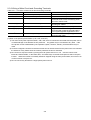
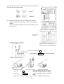
(8) Auxiliary power switching connector (CN UX) (18.5kW or higher)
For 18.5kW or higher inverters, if the supply voltage to the main circuit is within the range shown in
Table 2-3-3, reconnect the auxiliary power switching connector, CN UX, to U2. For other inverters, leave
the connector connected to U1. For details, see Figure 2-3-9.
Table 2-3-3 Voltage Ranges Requiring Reconnection of Auxiliary Power Switching Connector
Frequency [Hz]
Supply voltage range [ V ]
50
380 to 398
60
380 to 430
· Check that the number of phases and rated voltage of the product agree with those of the
AC power source.
· Do not connect any AC power source to the output terminals, U, V, and W.
Doing so may lead to injury.
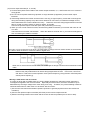
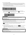
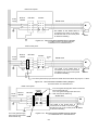
(9) Fan power switching connector (CN RXTX) (18.5kW or higher)
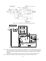
The VG7S accepts DC power inputs through a common DC terminal without using any optional equipment
when combined with a PWM converter as shown in Figure 2-3-8.
However, 18.5kW or higher inverters contain AC power operated parts such as AC cooling fan. When such
DC power inputs are used, reconnect the fan power switching connector, CN RXTX, inside the inverter to
R0-T0 as shown in Figure 2-3-6 and apply an AC power to the terminals, R0 and T0.
For details, see Figure 2-3-9.
Note: The fan power switching connector, CN RXTX, is normally connected to L1/R-L3/T.
Do not reconnect the
connector when no DC power inputs are used.
Always connect the same AC voltage as used for the main circuit to the auxiliary control power input
terminals, R0 and T0. Failure to do so deactivates the fan, which may overheat (OH1) and then fail the
inverter.
· Do not connect the fan power switching connector, CN RXTX, inside the inverter to a wrong terminal.
Doing so may fail the inverter.
· When DC power inputs are used, apply an AC power to R0 and T0 to drive the fan.
Failure to do so may fail the inverter.
2-10
CN RXTX
CN RXTX
Figure 2-3-7 Reconnection of Fan Power Switching Connector
18.5kW or higher
Earth
leakage
breaker
Magnetic
contactor
Power
source
PWM converter (RHC series)
P(+)
Filter
L1/R
L2/S
L3/T
+ C
N(-)
DB P1
Inverter unit
P(+)
N(-)
L1/R
+ C
L2/S
U
V
W
M
L3/T
CN RXTX
Fan
Reconnect CN RXTX
to R0-T0 .
R0
T0
Figure 2-3-8
An Example of Wiring of Inverter Combined with PWM Converter
Note 1: When a 15kW or lower inverter is combined with a PWM converter, do not directly connect any power
source to the auxiliary control power input terminals, R0 and T0. If connected to these terminals, the
power source should be insulated from the main power supply to the PWM converter with insulating
transformer.
Examples of wiring of the PWM converter are given in the instruction manual for PWM converter.
Note 2: 200V, 75kW or higher and 400V, 132kW or higher inverters contain no braking transistor.
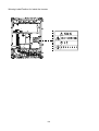
2-11
The switching connectors are mounted in the power PC board at the
top of the control circuit PC board.
CN UX
CN RXTX
Note: When removing either connector, hold the top of the jaw
between fingers to release the latch and remove by pulling
upward.
When mounting, fully insert the connector and apply the latch
until it clicks.
FRN18.5VG7S-2 to FRN55VG7S-2
FRN18.5VG7S-4 to FRN110VG7S-4
FRN75VG7S-2 to FRN90VG7S-2
FRN132VG7S-4 to FRN220VG7S-4
CN UX is connected to U1
and CN RXTX to L1/R-L3/T before factory shipment.
CN UX
:
U1
CN RXTX
:
L1/R-L3/T
The Figure applies when the inverter is
used with DC power inputs at a supply
voltage of 380-398V, 50Hz or 380-430V,
60Hz.
Figure 2-3-9 Power Switching Connectors (18.5kW or Higher Inverters Only)
2-12
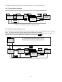
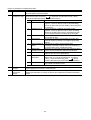
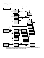
2-3-3 Wiring of Control Terminals
Functions of the control circuit terminals are described in Table 2-3-4. Each control terminal should be wired in
different ways, depending on its setting.
Analog output
Digital input
Analog input
Category
Table 2-3-4
Terminal
symbol
Terminal name
13
12
Potentiometer power supply
Voltage input
11
Ai1
Analog input common
Analog input 1
Ai2
M
FWD
Analog input 2
Analog input common
Forward operation command
REV
Reverse operation command
X1
X2
Digital input terminal 1
Digital input terminal 2
X3
X4
Digital input terminal 3
Digital input terminal 4
X5
X6
Digital input terminal 5
Digital input terminal 6
X7
X8
Digital input terminal 7
Digital input terminal 8
X9
Digital input terminal 9
PLC
PLC signal power supply
CM
Digital input common
AO1
Analog output terminal 1
AO2
Analog output terminal 2
AO3
M
Analog output terminal 3
Function
Supplies power (+10Vdc) to speed setting POT (1-5kW).
Controls the speed according to the external analog input voltage
command.
· 0 to +10V DC/0 to 100%
· Reversed operation with ± signals: 0 to ±10V DC/0 to ±100%
* Input resistance: 10kW
A common terminal for analog input signals
Inputs analog DC voltages between 0 to ±10V DC. For assignment
of signals, see 2.3.2 'Functions of Terminals'.
* Input resistance: 10kW
FWD-CM: ON... The motor runs in the forward direction.
FWD-CM: OFF... The motor decelerates and stops.
REV-CM: ON... The motor runs in the reverse direction.
REV-CM: OFF... The motor decelerates and stops.
Functions such as external coast-to-stop command, external alarm,
alarm reset, and multi-speed control can be turned on or off with
terminals X1 to X9. For details, see 2.3.2 'Functions of Terminals'.
<Digital Input Circuit Specifications>
Item
min.
typ.
max.
ON level
0V
2V
Operating
voltage
OFF level 22V
24V
27V
On-time operating current
3.2mA 4.5mA
Off-time permissible leak
0.5mA
current
Connected with output signal power source of PLC (Rated voltage: 24
(22-27)V DC ).
A common terminal for digital input signals
Outputs monitor signals at analog DC voltages between 0 and ± 10V
DC. For details of signals, see 2.3.2 'Functions of Terminals'.
* Connectable impedance: 3kW min.
Analog output common
2-13
Transistor output 1
Y2
Y3
Y4
Transistor output 2
Transistor output 3
Transistor output 4
CME
Transistor output common
30A,30B,
30C
Alarm relay output
(for any fault)
Y5A,Y5C
Relay output
RX(+),
RX(-)
TX(+),
TX(-)
SD(M)
RS485 communication
input/output
Input/output terminals for RS485 communication
Up to 31 inverters may be connected through multi-drop connections.
Terminating resistor (100W) can be connected via switch (SW3).
Communication shield cable
connection
Connected with shielded wires.
Temperature
detection
Speed detection
Communication
Relay output
terminals
Transistor output
Y1
PA,PB
Outputs signals such as Running, Speed equivalence, Overload early
warning, ... and z as transistor outputs from inverter to specified
ports. For details, see 2.3.2 'Functions of Terminals'.
<Transistor Output Circuit Specifications>
Item
min.
typ.
max.
ON
level
1V
2V
Operating
voltage
OFF level
24V
27V
On-time max. load current
50mA
Off-time permissible leak
0.1mA
current
A common terminal for transistor output terminals. Insulated from
terminals CM and 11.
Outputs alarm signal as relay contact output (1SPDT) when inverter
stops due to alarm.
Contact capacity: 250V AC, 0.3A, cos f = 0.3 (or 48V DC, 0.5A when
conformed with Low Voltage Directive)
You may choose to close contacts under unusual or normal
conditions.
You may select a signal as you may with Y1 to Y4 terminals.
Contact capacity is the same as with alarm relay output terminals.
PGP,PGM
Pulse generator 2-phase signal Connected with 2-phase signals from pulse generator
input
Pulse generator power supply Supplies power (+15V DC (switchable to +12V DC)) to PG.
FA,FB
Pulse generator output
CM
Pulse generator output
common
NTC/PTC thermistor
connection terminals
TH1,THC
Output pulse generator signal with frequency divided to 1/n.
programmable with function code E29.)
A common terminal for FA and FB.
(n is
Monitors motor temperature with NTC and PTC thermistors. For
PTC thermistor, motor overheat protection level can be set with
function code E32.
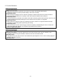
(1) Input terminals (13, 12, and 11)
1) Shielded wires as short as possible (20m or less) should be used
VR
for cables because these terminals handle weak analog signals
that are very susceptible to external noise. The shields should be 1k to 5kW
grounded to the earth, as a rule. If the signals are greatly affected
by external induction noise, however, connecting the shields to
terminal 11 may be advantageous.
2) When relay contacts are required in this circuit, use twin contacts
handling weak signals. Do not use contacts at terminal 11.
3) If any of these terminal is connected with an external analog signal
output unit, it may malfunction due to the noise generated by the
inverter, depending on the analog signal output circuit. In this
case, connect a ferrite core or capacitor to the external analog
signal output unit.
Figure 2-3-10
Figure 2-3-11
Protection against Noise (Example)
2-14
(2) Digital input terminals (FWD, REV, X1-X9, PLC, and CM)
1) The digital input terminals such as FWD, REV, and X1X9 are generally turned on/off between the CM terminal.
If turned on/off using an external power source and open
collector outputs from the programmable logic controller,
the terminals may malfunction due to current leak from
the external power source. In this case, connect the
external power source using the PLC terminal as shown
in Figure 2-3-12.
2) When inputs are made through relay contacts, use a
Figure 2-3-12
highly reliable relay contacts (Fuji Electric's HH54PW
Protection
against Current Leak
control relays, for example).
from External Power Source
(3) Transistor output terminals (Y1-Y4 and CME)
1) A circuit configuration as shown in the 'Transistor Output
Terminals' column of Table 2-3-4 is used. Take care not
to connect external power leads with reversed polarity.
2) When control relays are used, connect a surge
suppression diode to each end of the exciting coil.
(4) Miscellaneous
1) The control terminal leads should be kept as apart from the main circuit leads as possible to prevent
malfunction due to noise.
2) The control leads inside the inverter should be secured to prevent direct contact with the live part of the
main circuit (the main circuit terminal blocks, for example).
· The shield of each control cable does not serve as a reinforced insulator. If the shield is broken for some
reason, a high voltage in the main circuit may invade the control signal circuit. The Low Voltage
Directive in Europe also prohibits the users to wire the inverter with a main circuit lead in contact with a
control lead.
Doing so may lead to electric shock.
· Noise may be generated from the inverter, motor, and leads.
· Protect sensors and devices around the inverter from malfunction.
Failure to do so may lead to accident.
(5) Wiring of Control Circuits
1) FRN18.5VG7S-2 to FRN55VG7S-2
FRN18.5VG7S-4 to FRN110VG7S-4
(a) Pull the wiring out along the left side panel of the inverter as shown in Figure 2-3-13.
(b) Tie leads with bands (Insulock, for example) and secure to the hole (tie mounting hole A) on the left
side wall of the main circuit terminal block on the way outward. The bands should be 3.5mm or less in
width and 1.5 mm or less in thickness as they are to be passed through the holes (4mm dia.).
(c) If an optional printed circuit board is mounted, secure signal leads to the tie mounting hole B.
2-15
Figure 2-3-13
Routing Inverter (18.5 kW or
Higher) Control Circuit Leads
Figure 2-3-14
Securing Inverter (18.5 kW or
Higher) Control Circuit Leads
2) FRN132VG7S-4 to FRN160VG7S-4
(a) Pull the wiring out along the left side panel as shown in Figure 2-3-15.
(b) Tie leads with bands (Insulock, for example) and secure with cable tie holders on the beams on the way
outward. The bands should be 3.8 mm or less in width and 1.5 mm or less in thickness as they are to be
passed through square holes (3.8 × 1.5).
Figure 2-3-16
Securing Inverter Control Circuit Leads
Figure 2-3-15
Routing Inverter Control Circuit Leads
3) FRN75VG7S-2 to FRN90VG7S-2
FRN200VG7S-4 to FRN220VG7S-4
(a) Pull the wiring out along the left side panel as shown in Figure 2-3-17.
(b) Tie leads with bands (Insulock, for example) and secure with cable tie holders on the beams on the way
outward. The bands should be 3.8 mm or less in width and 1.5 mm or less in thickness as they are to
be passed through holes (3.8 × 1.5).
Figure 2-3-17
Routing Inverter Control Circuit Leads
Figure 2-3-18
Securing Inverter Control Circuit Leads
4) For FRN280VG7S-4 to FRN400VG7S-4
(a) Draw out along the left side panel of your inverter as in the Figure 2-3-17.
(b) Use an insulating clip above the main circuit terminal board L1/R to fix the wiring.
2-16
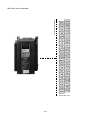
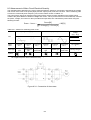
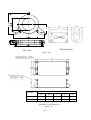
2-3-4 Terminal Arrangement Chart
l Main circuit terminals
FRN 0.75~7.5VG7S-2
FRN 3.7~7.5VG7S-4
FRN 37~55VG7S-2
FRN 75~110VG7S-4
FRN 11~15VG7S-2
FRN 11~15VG7S-4
FRN 75VG7S-2
FRN 18.5~22VG7S-2
FRN 18.5~22VG7S-4
FRN 90VG7S-2
FRN 132~220VG7S-4
FRN 30VG7S-2
FRN 30~55VG7S-4
FRN 280, 315VG7S-4
R0 T0
L1/R
L2/S
L2/S
L1/R
L3/T
U
P1
L3/T
G
P1
U
G
V
P(+) P(+)
Main circuit terminals
W
V
W
N(-) N(-)
Screw size R0,T0 : M4
G : M10
Other screw size : M12
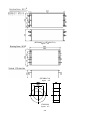
FRN 355,400VG7S-4
R0 T0
L1/R
L1/R
L2/S
L2/S
L3/T
L3/T
P1
P1
P(+)
P(+)
N(-)
N(-)
V
U
V
U
G
W
W
G
Screw size R0,T0 : M4
G : M10
Other screw size : M12
is main circuit terminals position.
2-17
Control circuit terminals
l Control circuit terminals
Screw size : M3
2-18
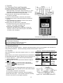
3. Test Run
3-1 Preliminary Check and Preparation
U,
z
Perform the following checks before starting operation.
(1) Check that the inverter is correctly wired.
Most importantly, the inverter output terminals, U, V, and
W should not be connected to a power source and the
earth terminal should be correctly grounded.
(2) No terminal or exposed live part should be shortcircuited or grounded.
(3) Check for loose terminals, connectors, and screws.
(4) Check that the motor is disconnected from mechanical
devices.
(5) Turn all switches off so that the inverter will not start or
malfunction when powered on.
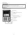
(6) After power-up of the inverter, check that:
1) the KEYPAD panel gives indications as shown in
Figure 3-1-2 (no alarm message), and
2) the inverter contained fan is rotating.
(However, when the function code H06 “Cooling fan
ON-OFF control” is used, there may be a case where
the built-in fan is stopped.)
V,
W
Figure 3-1-1
Inverter Connection Diagram
Figure 3-1-2
KEYPAD Panel Display with the Power ON
· Never turn the power switch on (closed) before mounting the face cover.
the inverter is energized.
· Do not handle the inverter with wet hand.
Doing so may lead to electric shock.
Do not remove the cover while
3-2 Operating Methods
There are many operating methods. Read this manual and select the one most suitable to the intended use
and operating conditions. General operating methods are described in Table 3-2-1.
Table 3-2-1 General Operating Methods
3-3 Test Run
After checking that no abnormal condition exists in 3.1, perform
a test run.
Before delivery, the inverter is programmed to be operated from
the KEYPAD panel (with function code F01 set to 0 and F02 to 0).
(1) Turn the power on. Check that the speed indicated by
blinking LEDs is 0r/min.
(2) Set the speed to a lower level around 100r/min using the
key.
(3) Press the F W D key to run the motor in the forward
direction or the R E V key to run in the reverse direction.
Press the S T O P key to stop the motor.
(4) Check that:
1) the motor runs in the selected direction (see Figure 3-3-1),
2) it revolves without any problem (motor roars and excessive
vibration), and
3) it smoothly accelerates or decelerates.
If no abnormal condition is observed, raise the operating
speed and check again. If the inverter is found to normally
function in the test run, start regular operation.
Ù
3-1
Operating
method
From
KEYPAD
panel
Through
external
signal
input
Speed controls
KEYPAD panel
keys
Ù
Ú
Ú
Ú
Operation
commands
FWD
,
REV
STOP
Contact inputs
(switches)
Terminals:
Variable resistor
FWD - CM
(POT) or analog
Terminals:
voltages
REV - CM
Figure 3-3-1
Motor Rotating Directions
If the inverter is found to normally function in the test run, start regular operation.
· If any abnarmal condition is observed with the inverter or motor, immediately stop and locate the cause
(see 'Troubleshooting').
· Even after the inverter stops outputting, touching any of the inverter output terminals, U, V, and W may
lead to electric shock if a voltage is continuously applied to the main circuit power terminals, L1/R, L2/S,
and L3/T, and auxiliary control power terminals, R0 and T0. The smoothing capacitor remains live after
the power switch is turned off and requires some time until completely discharged.
When touching an electric circuit after the shut-down, check that the charge lamp is off or check with a
multimeter that the voltage has been reduced to a safe level (24V or less).
· Setting a function code in a wrong manner or without fully understanding this manual may cause the
motor to revolve at an unacceptable torque or speed, possibly resulting in accident or injury.
Accident on injury may result.
3-2
4. KEYPAD Panel
· If the user set the function codes wrongly or without completely understanding this user’s manual, the
motor may rotate with a torque or at a speed not permitted for the machine.
Accident or injury may result.
· The STOP key is effective only when its function has been set. Install an emergency stop switch
separately.
Accident may result.
4-1 Appearance of KEYPAD Panel
(A) LED monitor
1500
(B) Auxiliary information indication for LED
monitor
(C) LCD monitor
(D) Indication on LCD monitor
(E) RUN LED (valid during KEYPAD
panel operation)
(F) Control keys
(G) Operation keys
4-1
(A) LED monitor:
Four-digit 7-segment display
Used to display various items of monitored data such as setting frequency, output frequency and alarm
code.
(B) Auxiliary information indication for LED monitor:
Selected units or multiple of the monitored data (on the LED monitor) are displayed on the top line of the
LCD monitor. The n symbol indicates selected units or multiple number. The symbol
indicates there
is an upper screen not currently displayed.
(C) LCD monitor:
Used to display such various items of information as operation status and function data. An operation
guide message, which can be scrolled, is displayed at the bottom of the LCD monitor.
(D) Indication on LCD monitor:
Displays one of the following operation status with n .
FWD: Forward operation REV: Reverse operation STOP: Stop
Displays the selected operation method:
REM: External signal LOC: KEYPAD panel COMM: Communication terminal JOG: Jogging mode
The symbol
indicates there is a lower screen not currently displayed.
(E) RUN LED (valid during KEYPAD panel operation):
Indicates that an operation command is being input by pressing the FWD or REV key.
(F) Control keys:
Used for inverter run and stop
FWD : Forward operation command
REV
: Reverse operation command
STOP :
(G) Operation keys:
Used for screen switching, data change, frequency setting, etc.
The Table 4-1-1 shows the main function of the operation keys.
Table 4-1-1 Functions of Operation Keys
Operation key
Main function
Used to switch the current screen to the menu screen or
PRG
switch to the initial screen in the operation/alarm mode.
Used to switch the LED monitor or to determine the entered
FUNC
DATA
frequency, function code, or data.
Used to change data, move the cursor up or down, or scroll
,
the screen
Used to move the cursor horizontally at data change. When
SHIFT
>>
this key is pressed with the up or down key, the cursor
moves to the next function block.
Used to cancel current input data and switch the displayed
screen. If an alarm occurs, this key is used to reset the trip
RESET
status (valid only when the alarm mode initial screen is
displayed).
Used to switch normal operation mode to jogging operation
STOP +
mode or vice versa. The selected mode is displayed on the
LCD monitor.
Switches operation method (from KEYPAD panel operation
to external signal operation or vice versa). When these keys
STOP + RESET
are pressed, function F02 data is also switched from 0 to 1 or
from 1 to 0. The selected mode is displayed on the LCD
indicator. (REM, LOC)
Ù
Ú
Ù
4-2
Stop command
4-2 Alarm Mode
Alarm detection order
Alarm code
OC
1=xxx xxx
xxxxxxxxxxxxx
PRGðPRG MENU
RESETðRESET
Number of successive
occurrences
Alarm name
Operational instruction
When a single alarm occurs, the
alarm mode screen appears
where the content of the alarm is
indicated.
When multiple alarms occur at the same time, the contents of the alarms can be checked using the
and
keys.
Ù
Ú
Alarm Detection Order
Operating keys LED display
5.
4.
3.
2.
1.
Blank
Blank
Blank
Blank
Blank
Blank
Blank
Blank
Blank
Blank
Blank
Ù
Ú
LCD display
5
4
3
2
1
0
-1
-2
-3
-4
-5
-6
-7
-8
-9
-10
Content
Alarm No. 5
Alarm No. 4
Alarm No. 3
Alarm No. 2
Alarm No. 1 (multiple alarms)
Latest alarm (single alarm/already has been reset)
1st latest alarm
2nd latest alarm
3rd latest alarm
4th latest alarm
5th latest alarm
6th latest alarm
7th latest alarm
8th latest alarm
9th latest alarm
10th latest alarm
4-3
4-3 KEYPAD Operation System (Hierarchical Structure of LCD Screens)
4-3-1 During Normal Operation
The basic KEYPAD operation system (hierarchical structure of screens) is illustrated below.
1500
Operation
mode screen
FUNC
DATA
1500
PRG
Program
menu screen
RESET
RESET
FUNC
DATA
1500
Function
screens
1500
FUNC RESET
DATA
Detailed
information
screen
PRG
Figure 4-3-1 KEYPAD Operation in Operation Mode
4-3-2 When an Alarm Raised Occurs
When an alarm occurs, the KEYPAD screen system is switched from the normal operation mode to the alarm
mode. The alarm mode screen appears where the alarm information is indicated.
The program menu, function, and detailed information screens are similar to those of normal operation. The
program menu screen can be switched to the alarm mode screen using PRG only.
1500
Normal KEYPAD operation (Figure 4-3-1)
Operation
mode screen
An alarm
occurs.
Alarm resetting process (including RESET )
Alarm
Alarm mode
PRG
screen
Alarm
Program menu
FUNC
DATA
FUNC
DATA
Alarm
screen
Function
screens
RESET
PRG
4-4
FUNC RESET
DATA
Alarm
Detailed
information
screen
Outline of Indications on Different Screens
No.
Screen name
Description
1
Operation mode You can change motor speed or switch LED monitor when this screen is shown on
KEYPAD during normal operation.
2
Program menu
Function menu is shown on this screen for your selection. Select a desired
(Program mode) function from menu and press FUNC
DATA to call screen for selected function. Menu
contains the following options as KEYPAD functions.
No.
1
Menu item
Function menu
2
CHECK DATA
3
MONITOR
4
I/O CHECK
5
MAINTENANCE
INFO
6
MEASURE
LOAD FACTOR
ALARM INFO
7
3
4
Function
screens
Detailed
information
screen
8
ALARM
HISTORY
9
COPY DATA
Outline
If this is selected, a name list of function codes
appears. Select a desired code to call data setting
screen for that code where its setting can be checked
or changed.
If this is selected, a data list of function codes
appears. Select a desired code to check its setting.
Similar to the SET DATA above, data setting screen
can be selected where its setting can be changed.
This screen is used as operation status monitor to
check various data.
This screen is used to check status of inverter and
optional analog input/output and digital input/output
signals.
This screen is used to check maintenance
information including inverter status, life expectancy,
communication errors, and ROM version.
Maximum and average currents and average braking
power can be measured to determine load factor.
This screen is used to check operation status and I/O
status at the time of the latest alarm.
This screen is used to check the latest alarm, multiple
alarms that occurred at the same time, and alarm
history. Select an alarm and press FUNC
DATA to check
cause of that alarm and troubleshooting information.
Function code settings for an inverter can be stored
and copied to another inverter.
When a function is selected from program menu, the corresponding function
screen appears for execution of that function.
Functions that cannot be executed by function screens (change of function code
settings and indication of causes of alarms) are displayed by detailed information
screen.
4-5
4-3-3 Program Mode
The KEYPAD operation (hierarchical structure of screens) in the program mode is illustrated below.
Program mode
*1
(1)
1500
FUNC
OC
Function menu
Ù,Ú : Selects a code
FUNC
:Selects a directory
DATA
>>+Ù / Ú : Jumps to
DATA
DATA
previous/next group
>> +PRG
*1
(2)
RESET
: Saves data
(Code +1)
FUNC
1500
>> +PRG
1500
OC
CHECK DATA
Ù,Ú : Selects a code
FUNC
DATA :Selects a directory
>> +Ù / Ú : Jumps to
OC
SET DATA
Ù,Ú : Changes a value
STOP+Ù,Ú:
Changes a special value
>> : Moves cursor
FUNC
: Saves data
(Code +1)
DATA
RESET
previous/next group
FUNC
DATA
1500
(3)
1500
OC
Ù
MONITOR
OC
I/O CHECK
Ú
運転状態モニタ
運転状態モニタ
運転状態モニタ
1) Input signals
1) Operation status 1
Ù
運転状態モニタ
Ú
2) Input
signals (via COMM)
運転状態モニタ
2) Operation status 2
3) Output
signals
運転状態モニタ
4) Analog input signals
運転状態モニタ
(4)
5) Analog output status
運転状態モニタ
6) Operation status
運転状態モニタ
1500
OC
1500
FUNC
Program menu
Ù,Ú: Selects a
function between
(1) and (9).
OC
MAINTENANCE INFO
DATA
運転状態モニタ
Ù
Ú
運転状態モニタ
12)運転状態モニタ
DIOA input status
13) DIOA input status (via
COMM)
運転状態モニタ
1) Operation status 1
運転状態モニタ
14) DIA/DIB input status
2) Operation
status 2
運転状態モニタ
3) Operation
status 3
運転状態モニタ
15) DIOB input status
3) Operation
status
運転状態モニタ
16) DIOB output status
4) Communication
運転状態モニタ status
4) Communication status
5) ROM version 1
6) ROM version 2
(6)
運転状態モニタ
11)運転状態モニタ
PG input status
運転状態モニタ
2) Operation
status 2
運転状態モニタ
1500
10) AIO input status
運転状態モニタ
1) Operation status 1
(5)
運転状態モニタ
OC
ALARM INFO
運転状態モニタ
RESET
In operation
mode only
1500
7) Effective sets of
motors/parameters
運転状態モニタ
8) Optional I/O terminal
status
運転状態モニタ
9) Optional communication
terminal status
5) Input
signals
運転状態モニタ
6) Input signals (via COMM)
運転状態モニタ
OC
Ù
Ú
7) Output signals
運転状態モニタ
MEASURE LOAD
FACTOR
F/D : Starts/stops
measurement
8) Operation status
運転状態モニタ
9) DIOA input status
運転状態モニタ
10) DIOA input status (via
COMM)
運転状態モニタ
11)運転状態モニタ
Alarm history 1
(7)
12) Multiple alarms
13) Alarm history 2
14) Alarm history 3
1500
COPY
COPY DATA
Ù,Ú: Selects a
process
F/D: Starts copying
1500
*1
(9)
(8)
OC
ALARM HISTORY
Ù,Ú : Selects an alarm
1500
OC
CAUSE
Ù,Ú : Scrolls over
screens
FUNC
DATA
RESET
*1: When the limiting function by the password (function code L01, L02) is active, you cannot select until the
password setting is completed. Usually you can select, though.
4-6
5. Function Selection
· When the retry function is selected, the inverter may restart automatically after tripping.
(Design the machine to ensure personal safety in the event of restart)
Accident may result.
· When the torque limiting function is selected, operating conditions may differ from preset conditions
(acceleration/deceleration time or speed). In this case, personal safety must be assured.
Accident may result.
· If AUTO RESTART is selected in the restart mode after momentary power failure (function code F14), the
inverter restarts automatically starting the motor rotation when the power is re-supplied.
Accident may result.
· When auto tuning (function code H01) is started, the motor, machine or equipment starts and stops
repeatedly. Ensure safety before performing auto tuning.
Accident may result.
· If the user set the function codes wrongly or without completely understanding this user’s manual, the
motor may rotate with a torque or at a speed not permitted for the machine.
Accident or injury may result.
· During pre-excitation, the speed adjuster does not function and the motor may be rotated by load
disturbance. When using pre-excitation, therefore, also use the machine brake.
Injury may result.
· If improper data is set at the function code related with speed adjuster as in the case of setting high gain
abruptly, the motor may hunt.
Injury may result.
5-1
Underline indicates a factory setting.
Items without underline have different factory settings according to capacity.
F: Fundamental Functions
Fcode
f00
Communication
address
485
Link number
number
0h
80(
Function name
50 h) Data
protection
Setting range
Fcode
0 to 1
f27
1h
(
h) Speed setting
N1
485
Link number
number
1Bh
95(
0 : Data change enable
3 : level 3
f36
24h
(
0 to 7
0 : KEYPAD operation ( ∧ and ∨ key)
f37
f38
4 : UP/DOWN control 2 (initial speed = last value)
25h
96(
26h
97(
5 : UP/DOWN control 3 (initial speed = Creep
speed 1 or 2)
h) 30RY
operation
mode
60 h) Stop speed
(Level)
61 h) Stop speed
(Detection
method)
7 : DIB card input
The method of operation is set.
50 to 1500 to 24000 r/min
f04
4h
82(
52 h) M1-Rated
speed
50 to 24000 r/min
f05
5h
83(
53 h) M1-Rated
voltage
80 to 999 V
f07
7h
84(
54 h) Acceleration
time 1
0.01 to 5.00 to 99.99s
62 h) Stop speed
(Zerospeed
holding time)
f40
28h
99(
63 h) Torque limiting 0 to 3
mode 1
0 : Torque limiting invalid
8h
85(
55 h) Deceleration
time 1
3 : Torque current limiting
f41
29h 100(
64 h) Torque limiting 0 to 3
mode 2
0 : Same limiting level (level 1) for 4 quadrants
1 : Drive torque limiting (level 1),
and Brake torque limiting (level 2)
2 : Upper torque limiting (level 1),
and Lower torque limiting (level 2)
3 : Same limiting level for 4 quadrants
(level 1 and level 2 changeover)
100.0 to 999.9s
Level 1 and 2 is the data setting of the definition by F42,
43 ahead.
0.01 to 5.00 to 99.99s
f42
2Ah 101(
100.0 to 999.9s
1000 to 3600s
f10
Ah
86(
56 h) M1 Electronic
thermal
overload relay
(Select)
0 to 2
The motor overheating protection operates by using
NTC thermistor with the motor only for VG. In this
case, please make setting F10 Electronic thermal
"Inactive".
f12
f14
Ch
Eh
88(
(
57 h) M1 Electronic
thermal
overload relay
(Level)
58 h) M1 Electronic
thermal
overload relay
(Thermal time
constant)
h) Restart mode
after
momentary
power failure
1 : Ai terminal input value [TL-REF1]
2 : DIA card input
5 : PID output
f43
2Bh 102(
66 h) Torque limiter
value
(level 2)
selection
0.01 to 99.99A
0 to 5
0 : Internal preset value by F45
1 : Ai terminal input value [TL-REF2]
2 : DIA card input
3 : DIB card input
100.0 to 999.9A
4 : Link enabled
1000 to 2000A
5 : PID output
0.5 to 75.0 min
f44
2Ch 103(
67 h) Torque limiter
value
f45
2Dh 104(
68 h) Torque limiter
value
-300 to 150 to 300 %
(level 1)
0 to 5
0 : Inactive (Trip and alarm when power failure occurs.)
f46
1 : Inactive (Trip, and alarm when power recovers.)
3 : Active (Smooth recovery by continuous operation
mode)
2Eh 105(
f47
2Fh 106(
4 : Active (Momentarily stops and restarts at speed on
power failure)
11h
f18
12h
(
f20
14h
89(
59 h) DC brake
(Starting
speed)
f21
15h
90(
5A h) DC brake
0 to 100 %
(Braking level)
f22
16h
91(
5B h) DC brake
(Braking time)
h) Gain (terminal
12 input)
0.0 to 100 to 200.0 %
h) Bias (terminal
12 input)
-24000 to 0 to 24000 r/min
f48
30h
(
31h
(
f50
32h
f51
33h 251(
(
0.0 to 30.0 s
5C h) Starting speed 0.0 to 150.0 r/min
(Speed)
(The frequency is limited so as not to become 0.1Hz or
less. (When using sensoless or V/F control))
f24
18h
93(
5D h) Starting speed 0.00 to 10.00 s
(Holding time)
f26
1Ah
94(
5E h) Motor sound
-300.00 to 0.00 to 300.00 %
This set value can be added to the torque reference
value.
h) Torque bias
set 2
-300.00 to 0.00 to 300.00 %
This set value can be added to the torque reference
value.
h) Torque bias
set 3
-300.00 to 0.00 to 300.00 %
This set value can be added to the torque reference
value.
h) Torque bias
0.00 to 1.00 s
activation timer ( 300% / 1.00s )
Time up to 300% is set.
0.1 to 30.0 s
92(
6A h) Torque bias
set 1
This is used when mechanical loss of the load makes
amends.
TB1, 2 and 3 are switched by DI and are used.
0.0 : (Inactive)
17h
-300.00 to 0.00 to 300.00 %
TB1, 2 and 3 are switched by DI and are used.
f49
0 to 3600 r/min
f23
69 h) Mechanical
loss
compensation
TB1, 2 and 3 are switched by DI and are used.
5 : Active (Momentarily stops and restarts at starting
speed)
f17
-300 to 10 to 300 %
(level 2)
2 : Inactive (Deceleration to stop, and trip and alarm.)
(
0 : Internal preset value by F44
4 : Link enabled
2 : Active (for Inverter motor, with separate cooling fan)
87(
0 to 5
3 : DIB card input
1 : Active (for 4-pole standard motor, with self-cooling
fan)
Bh
65 h) Torque limiter
value
(level 1)
selection
0 : Inactive (When you use the motor only for VG)
f11
0.00 to 0.50 to 10.00 s
2 : Power limiting
1000 to 3600s
f08
1 : Detected value
1 : Torque limiting
The change of REMOTE/LOCAL is possible also by
RST+STOP key to the keypad panel. This operation
corresponds to writing data of F02.
51 h) M1 Maximum
speed
0 to 1
0 : Reference value
98(
1 : FWD or REV signal input (REMOTE)
81(
0.0 to 10.0 to 150.0 r/min
(The frequency is limited so as not to become 0.1Hz or
less. (When using sensoless or V/F control))
27h
0 : KEYPAD operation (FWD or REV or STOP key)
(LOCAL)
3h
1 : The relay(30) exites on normal mode.
f39
0 to 1
f03
0 to 1
0 : The relay(30) exites on trip mode.
It is fixed 0 to use the V/F control.
6 : DIA card input
h) Operation
method
0 : level 0
2 : level 2
3 : UP/DOWN control 1 (initial speed = 0 r/min)
(
0 to 3
1 : level 1
2 : Analog input (0 to +10VDC)
2h
5F h) Motor sound
(Sound tone)
Setting range
This is a function to protect writing from the Keypad
panel.
1 : Analog input (0 to ±10VDC)
f02
Function name
1 : Data protection
The protection of writing from the link (T-Link, RS485,
etc.) is defined with H29 "Link function protection".
f01
Communication
address
FB h) Torque
reference
monitor
(polarity)
0 to 1
Polarity selection of the data output related to torque
(AO, Keypad panel,code M)
0 : Display with torque polarity
1 : (+) for driving mode, and (-) for braking mode
f52
0.75 to 7 to 15 kHz
(Carrier Freq.) A factory setting value of 75kW or more is 10kHz.
34h
(
h) LED monitor
coefficient
(Display
coefficient A)
-999.00 to 1.00 to 999.00
The conversion coefficient to decide load axis rotation
speed and the display value at the line speed displayed
in LED are set.
Display value = Motor speed × (0.01 to 200.00)
You can change the setting of a function indicated by
during operation.
You should stop operation to change the setting of other functions.
The set data is effective only by 0.01 to 200.00 and
outside the range is invalid.
5-2
Underline indicates a factory setting.
Items without underline have different factory settings according to capacity.
Fcode
f53
Communication
address
485
Link number
number
35h
(
Function name
h) LED monitor
coefficient
(Display
coefficient B)
Setting range
Fcode
h) LED display
filter
3Eh 108(
6C h) ASR1 (I-gain)
0.010 to 0.200 to1.000 s
f63
3Fh 109(
6D h) ASR1 (Feed
forward gain)
0.000 to 9.999 s
f64
40h 110(
6E h) ASR1 (Input
filter)
0.000 to 0.040 to 5.000 s
f65
41h
6F h) ASR1
(Detection
filter)
0.000 to 0.005 to 0.100 s
0.0 to 0.2 to 5.0 s
f66
42h 112(
70 h) ASR1 (Output
filter)
0.000 to 0.002 to 0.100 s
Filter to prevent LED from flickering by change of the
display data.
f67
43h 113(
71 h) S-curve
0 to 50 %
P control when setting 1.000
111(
The filter is effective in all the data selected with F55.
f55
37h
(
h) LED
(Selection)
(Acc start side)
0 to 28
f68
44h 114(
72 h) S-curve (Acc
end side)
0 to 50 %
0 : Detected speed 1 or reference speed (r/min)
(depending on F56 while motor is stopped)
f69
45h 115(
73 h) S-curve (Dec
start side)
0 to 50 %
f70
46h 116(
74 h) S-curve (Dec
end side)
0 to 50 %
f73
49h
f74
4Ah 117(
75 h) Pre-exiting
time
0.0 to 10.0 s
f75
4Bh 118(
76 h) Pre-excitation
initial Level
100 to 400 %
f76
4Ch
1 : Speed reference value 4 (ASR input) (r/min)
2 : Output frequency after slip compensation (Hz)
3 : Torque current reference (%)
4 : Torque reference value (%)
5 : Torque (calculated value) (%)
6 : Inverter input power (kW or HP) (depending on F60)
7 : Output current (A)
8 : Output voltage (V)
9 : DC link circuit voltage (V)
10 : Magnetic flux reference (%)
(
(
h) Magnetic flux
at light load
h) Speed limiter
(Mode select)
11 : Magnetic flux (calculated value) (%)
12 : Motor temperature (℃) ("---" is displayed when NTC
thermistor unused.)
16 : Ai adjusted value (Ai1) (%)
17 : Ai adjusted value (Ai2) (%)
18 : Ai adjusted value (Ai3) (%)
19 : Ai adjusted value (Ai4) (%)
The following data becomes non-display by the mode
on the option.
f77
4Dh
79(
4F h) Speed limiting
(Level 1)
-110.0 to 100.0 to 110.0 %
f78
4Eh 254(
FE h) Speed limiting
(Level 2)
-110.0 to 100.0 to 110.0 %
f79
4Fh 119(
77 h) Motor
selection (M1,
M2, M3)
0 to 2
20 : PID reference (%) (Display at the PID mode)
The signal input by the terminal is given to priority.
22 : PID output value (%) (Display at the PID mode)
M1 select ; (MCH2,MCH3)=(OFF,OFF) (If there is
no allocation)
23 : Option monitor 1 (HEX) (Displayed with use of
option)
M2 select ; (MCH2,MCH3)=(ON ,OFF)(ON,ON)
24 : Option monitor 2 (HEX) (Displayed with use of
option)
1 : M2 select (x function inactive)
2 : M3 select (x function inactive)
25 : Option monitor 3 (DEC) (Displayed with use of
option)
f80
26 : Option monitor 4 (DEC) (Displayed with use of
option)
0 to 1
Change of the display on F55 when the motor is
stopping.
The corresponding data is speed (0), load shaft rotation
speed (13), and line speed (14).
0 : Speed reference (r/min)
1 : Speed feedback (r/min)
(
h) LCD
(Selection)
0 to 1
Change of operation mode display on Keypad panel
0 : Operation guide (State of operation, Direction of
rotation)
1 : Bar graph monitor (Speed,
f58
3Ah
(
h) LCD
(Language)
Current,
Torque)
0 to 7
0 : Japanese
1 : English
2 : German
3 : French
4 : Spanish
5 : Italian
6 : Chinese
7 : Korean
f59
3Bh
(
h) LCD
(Contrast)
0 to 5 to 10
f60
3Ch
(
h) Output unit
selection (kW
or HP)
0 to 1
0 (Soft) to 10 (Hard)
The unit of inverter power consumption and motor
(M1,2,3) of the function setting is defined.
0 : kW
1 : HP
f61
3Dh 107(
(
h) Current rating
switching
0 to 2
0 : CT (Overload current 150%)
2 : HT (Overload torque 200/170%)
28 : Option monitor 6 (DEC) (Displayed with use of
option)
39h
50h
1 : VT (Overload current 110%)
27 : Option monitor 5 (DEC) (Displayed with use of
option)
f57
An effective motor (M1, 2 or 3) is selected by the
function or terminal.
0 : M1 select
21 : PID feedback value (%) (Display at the PID mode)
h) LED (Display
at stop mode)
0 : Limiting level 1 for forward rotation, and limiting level
2 for reverse rotation
3 : Forword (Level 1) and reverse (Level 2). Add the [12]
input as a bias.
15 : Ai adjusted value (12) (%)
(
0 to 3
2 : Limiting level 1 for upper limit, and limiting level 2 for
lower limit
14 : Line speed (m/min) (depending on F56)
38h
10 to 100 %
1 : Limiting level 1 for both side rotation
13 : Load shaft speed (r/min) (depending on F56)
f56
Setting range
f62
Display value = (Reference value or feedback value) *
(Display coefficient A - B) + B
(
Function name
-999.00 to 1.00 to 999.00
Display coefficient B ; Minimum value
36h
485
Link number
number
The conversion coefficient to decide the reference value
of the PID adjustment machine and the display value
(amount of the process) of the amount of feedback is
set by using display coefficient A and B.
Display coefficient A ; Maximum value
f54
Communication
address
6B h) ASR1 (P-gain) 0.1 to 10.0 to200.0 (times)
You can change the setting of a function indicated by
during operation.
You should stop operation to change the setting of other functions.
5-3
Underline indicates a factory setting.
Items without underline have different factory settings according to capacity.
E: Extension Terminal Functions
Fcode
e01
Communication
address
485
Link number
number
101h 120(
Function name
78 h) X1 terminal
function
Fcode
Setting range
0 to 63
Communication
address
485
Link number
number
e12
10Ch 131(
83 h) X13 terminal
function
e13
10Dh 132(
84 h) X14 terminal
function
e14
10Eh
0 to 3 : Multistep speed selection (1 to 15 steps)
(0 : SS1, 1 : SS2, 2 : SS4, 3 : SS8)
4, 5 : ASR and ACC/DEC time selection (4 steps)
(4 : RT1, 5 : RT2)
Function name
(
6 : 3 wire operation stop command (HLD)
7 : Coast-to-stop command (BX)
h) X terminal
function
normal
open/closed
Setting range
0 to 25 to 63
0 to 25 to 63
0000 to 01FF
Setting of normal state of X1-X9.
0 : Normally open
1 : Normally closed
8 : Alarm reset (RST)
e15
9 : External Alarm (THR)
10Fh 133(
10 : Jogging operation (JOG)
85 h) Y1 terminal
function
0 to 1 to 47
0 : Inverter running (RUN)
1 : Speed existence signal (N-EX)
11 : Speed setting 2 / Speed setting 1 (N2/N1)
2 : Speed agreement signal (N-AG)
12 : Motor M2 selection (M-CH2)
3 : Speed egilivarent signal (N-AR)
13 : Motor M3 selection (M-CH3)
4 : Speed level detection 1 (N-DT1)
14 : DC brake command (DCBRK)
5 : Speed level detection 2 (N-DT2)
15 : ACC/DEC cleared to zero (CLR)
6 : Speed level detection 3 (N-DT3)
16 : Creep speed switching in UP/DOWN control
7 : Stopping on undervoltage (LU)
(CRP-N2/N1)
8 : Detected torque polarity (Braking/Driving) (B/D)
17 : UP command (UP)
9 : Torque limiting (TL)
18 : DOWN command (DOWN)
10 : Torque detection 1 (T-DT1)
19 : Write enable for KEYPAD (WE-KP)
11 : Torque detection 2 (T-DT2)
20 : PID control cancel (N/PID)
12 : KEYPAD operation mode (KP)
21 : Inverse mode changeover (IVS)
13 : Inverter stopping (STP)
22 : Interlock signal for 52-2 (IL)
14 : Operation ready output (RDY)
23 : Write enable through link (WE-LK)
15 : Magnetic flux detection signal (MF-DT)
24 : Operation selection through link (LE)
16 : Motor M2 selection status (SW-M2)
25 : Universal DI (U-DI)
17 : Motor M3 selection status (SW-M3)
26 : Pick up start mode (STM)
18 : Mechanical brake release signal (BRK)
27 : Synchronization command (PG (PR) optional
function) (SYC)
19 : Alarm indication signal 1 (AL1)
28 : Zero speed locking command (LOCK)
20 : Alarm indication signal 2 (AL2)
29 : Pre-exiting command (EXITE)
21 : Alarm indication signal 4 (AL4)
30 : Speed reference limiter cancel (N-LIM)
22 : Alarm indication signal 8 (AL8)
23 : Fan operation signal (FAN)
(Related function : F76, F77, F78)
31 : H41 [torque reference] cancel (H41-CCL)
24 : Auto-resetting (TRY)
32 : H42 [torque current reference] cancel (H42-CCL)
25 : Universal DO (U-DO)
33 : H43 [magnetic flux reference] cancel (H43-CCL)
26 : Heat sink overheat early warning (INV-OH)
34 : F40 [torque limiter mode 1] cancel (F40-CCL)
27 : Synchronization completion signal (SY-C)
35 : Torque limiter 2 / Torque limiter 1 (TL2/TL1)
28 : Lifetime alarm (LIFE)
36 : Bypass from ramp function generator (BPS)
29 : Under acceleration (U-ACC)
37, 38 : Torque bias reference 1/2
30 : Under deceleration (U-DEC)
(37 : TB1,
31 : Inverter overload early warning (INV-OL)
38 : TB2)
39 : DROOP selection (DROOP)
32 : Motor overheat early warning (M-OH)
40 : Zero hold command for Ai1 (ZH-AI1)
33 : Motor overload early warning (M-OL)
41 : Zero hold command for Ai2 (ZH-AI2)
34 : DB overload early warning (DB-OL)
42 : Zero hold command for Ai3 (option) (ZH-AI3)
35 : Link transmission error (LK-ERR)
43 : Zero hold command for Ai4 (option) (ZH-AI4)
36 : Load adaptive control under limiting (ANL)
44 : Ai1 polarity change (REV-AI1)
37 : Load adaptive control under calculation (ANC)
45 : Ai2 polarity change (REV-AI2)
38 : Analog torque bias hold (TBH)
39 to 47 : Option DO1 to 9 (O-DO1 to O-DO9)
46 : Ai3 polarity change (option) (REV-AI3)
47 : Ai4 polarity change (option) (REV-AI4)
e16
110h 134(
86 h) Y2 terminal
function
0 to 2 to 47
e17
111h 135(
87 h) Y3 terminal
function
0 to 3 to 47
e18
112h 136(
88 h) Y4 terminal
function
0 to 4 to 47
e19
113h 137(
89 h) Y5 terminal
function
0 to 14 to 47
e20
114h 138(
8A h) Y11 terminal
function
0 to 26 to 47
e21
115h 139(
8B h) Y12 terminal
function
0 to 26 to 47
e22
116h 140(
8C h) Y13 terminal
function
0 to 26 to 47
e23
117h 141(
8D h) Y14 terminal
function
0 to 26 to 47
48 : Inverse mode of PID output (PID-INV)
49 : PG alarm cancel (PG-CCL)
50 : Undervoltage cancel (LU-CCL)
51 : Ai torque bias hold [H-TB]
52 : STOP1 (The motor stops with normal deceleration
time.) (STOP1)
53 : STOP2 (The motor stops with deceleratime 4)
(STOP2)
54 : STOP3 (The motor stops with max, torque.)
(STOP3)
55 : DIA data latch (DIA option) (DIA)
56 : DIB data latch (DIB option) (DIB)
57 : Mulitiwinding motor cancel (SI (MWS) option)
(MT-CCL)
e24
118h 142(
102h 121(
79 h) X2 terminal
function
0 to 1 to 63
8E h) Y15 terminal
function
0 to 26 to 47
e02
e25
119h 143(
0 to 26 to 47
e03
103h 122(
7A h) X3 terminal
function
0 to 2 to 63
8F h) Y16 terminal
function
e26
11Ah 144(
104h 123(
7B h) X4 terminal
function
0 to 3 to 63
90 h) Y17 terminal
function
0 to 26 to 47
e04
e27
11Bh 145(
0 to 26 to 47
e05
105h 124(
7C h) X5 terminal
function
0 to 4 to 63
91 h) Y18 terminal
function
e28
11Ch
e06
106h 125(
7D h) X6 terminal
function
0 to 5 to 63
e07
107h 126(
7E h) X7 terminal
function
0 to 7 to 63
e08
108h 127(
7F h) X8 terminal
function
0 to 8 to 63
e09
109h 128(
80 h) X9 terminal
function
0 to 9 to 63
e10
10Ah 129(
81 h) X11 terminal
function
0 to 25 to 63
e11
10Bh 130(
82 h) X12 terminal
function
0 to 25 to 63
58 to 63 : Option Di 1/2/3/4/5/6 (O-DI1 to 6)
(
h) Y terminal
function
normally
open/closed
0000 to 001F
Setting of normal state of Y1to Y4,RY.
0 : Normally open
1 : Normally close
You can change the setting of a function indicated by
during operation.
You should stop operation to change the setting of other functions.
5-4
Underline indicates a factory setting.
Items without underline have different factory settings according to capacity.
Fcode
e29
Communication
address
485
Link number
number
11Dh 146(
Function name
92 h) PG pulse
output
selection
Setting range
Fcode
0 to 9
Communication
address
485
Link number
number
133h
(
h) Ai3 function
selection
0 to 18
e52
134h
(
h) Ai4 function
selection
0 to 18
e53
135h
(
h) Gain
-10.000 to 1.000 to 10.000 (times)
adjustment for
Use ∧ or ∨ key to write data onto RAM during editing
analog input
with KEYPAD panel.
(Ai1)
Using F/D key causes data writing onto nonvolatile
memory.
e54
136h
(
h) Gain
-10.000 to 1.000 to 10.000 (times)
adjustment for
Use ∧ or ∨ key to write data onto RAM during editing
analog input
with KEYPAD panel.
(Ai2)
Using F/D key causes data writing onto nonvolatile
memory.
e55
137h
(
h) Gain
-10.000 to 1.000 to 10.000 (times)
adjustment for
Use ∧ or ∨ key to write data onto RAM during editing
analog input
with KEYPAD panel.
(Ai3)
Using F/D key causes data writing onto nonvolatile
memory.
e56
138h
(
-10.000 to 1.000 to 10.000 (times)
h) Gain
adjustment for
Use ∧ or ∨ key to write data onto RAM during editing
analog input
with KEYPAD panel.
(Ai4)
Using F/D key causes data writing onto nonvolatile
memory.
e57
139h
(
h) Bias
-100.0 to 0.0 to 100.0 %
adjustment for
Use ∧ or ∨ key to write data onto RAM during editing
analog input
with KEYPAD panel.
(Ai1)
Using F/D key causes data writing onto nonvolatile
memory.
e58
13Ah
(
h) Bias
-100.0 to 0.0 to 100.0 %
adjustment for
Use ∧ or ∨ key to write data onto RAM during editing
analog input
with KEYPAD panel.
(Ai2)
Using F/D key causes data writing onto nonvolatile
memory.
e59
13Bh
(
h) Bias
-100.0 to 0.0 to 100.0 %
adjustment for
Use ∧ or ∨ key to write data onto RAM during editing
analog input
with KEYPAD panel.
(Ai3)
Using F/D key causes data writing onto nonvolatile
memory.
e60
13Ch
(
h) Bias
-100.0 to 0.0 to 100.0 %
adjustment for
Use ∧ or ∨ key to write data onto RAM during editing
analog input
with KEYPAD panel.
(Ai4)
Using F/D key causes data writing onto nonvolatile
memory.
e61
13Dh
(
h) Filter
0.000 to 0.010 to 0.500 s
adjustment for
analog input
(Ai1)
e62
13Eh
(
h) Filter
0.000 to 0.010 to 0.500 s
adjustment for
analog input
(Ai2)
e63
13Fh
(
h) Filter
0.000 to 0.010 to 0.500 s
adjustment for (When the AIO option is installed, this is displayed.)
analog input
(Ai3)
e64
140h
(
h) Filter
0.000 to 0.010 to 0.500 s
adjustment for (When the AIO option is installed, this is displayed.)
analog input
(Ai4)
e65
141h
(
h) Increment/
decremrnt
limiter (Ai1)
0.00 to 60.00 s
e66
142h
(
h) Increment/
decremrnt
limiter (Ai2)
0.00 to 60.00 s
e67
143h
(
h) Increment/
decremrnt
limiter (Ai3)
0.00 to 60.00 s
e68
144h
(
h) Increment/
decremrnt
limiter (Ai4)
0.00 to 60.00 s
2 : 1/4
3 : 1/8
4 : 1/16
5 : 1/32
6 : 1/64
0 to 6: Internal PG inputs are output after being divided.
7 : Pulse oscillation mode (A/B 90° phase difference
signal)
Internal speed reference is output after pulse
conversion.
8 : PG (PD)
Pulse inputs for position encoder are directly output.
9 : PG (PR)
Pulse inputs for position command are directly
output.
e30
e31
e32
11Eh
11Fh
(
(
120h 205(
h) Motor OH
protection
(temperature)
100 to 150 to 200°C
h) M-OH early
warning
(temperature)
50 to 75 to 200 °C
CD h) M1-M3
(operation
level PTC)
It is effective when NTC thermistor is used with selected
motor (M1,M2).
0.00 to 1.60 to 5.00 V
121h
(
h) INV-OL early
warning
25 to 90 to 100 %
122h
(
h) M-OL early
warning
25 to 90 to 100 %
e35
123h
(
h) DB overload
protection
0 to 100 %
e36
124h
(
h) DB-OL early
warning
0 to 80 to 100 %
e37
125h
(
h) DB thermal
time constant
0 to 300 to 1000 s
e38
126h 147(
000 to 111
(N-DT1) (N-DT2) (N-DT3)
0 : Detected speed
1 : Speed reference
Only reference values are effective under VF control.
e39
127h 148(
94 h) N-DT1 Level
0 to 1500 to 24000 r/min
e40
128h 149(
95 h) N-DT2 Level
-24000 to 1500 to 24000 r/min
e41
129h 150(
96 h) N-DT3 Level
-24000 to 1500 to 24000 r/min
e42
12Ah 151(
97 h) N-AR
1.0 to 3.0 to 20.0 %
detection width
e43
12Bh 152(
98 h) N-AG
1.0 to 3.0 to 20.0 %
detection width
e44
12Ch 153(
99 h) N-AG off-delay 0.000 to 0.100 to 1.000 s
timer
e45
12Dh 154(
9A h) Speed
disagreement
alarm
e46
12Eh 155(
9B h) Torque
0 to 30 to 300 %
detection level When the V/F control is used, the calculation value is
1
set.
e47
12Fh 156(
9C h) Torque
0 to 30 to 300 %
detection level When the V/F control is used, the calculation value is
2
set.
e48
130h 157(
9D h) Magnetic flux 10 to 100 %
detection level
e49
131h
h) Ai1 function
selection
(When the AIO option is installed, this is displayed.)
(When the AIO option is installed, this is displayed.)
0 to 21
0 to 18
0 : Input signal off (OFF)
1 : Auxiliary speed setting 1 (before ramp function)
(±10 V / ±Nmax) (AUX-N1)
2 : Auxiliary speed setting 2 (after ramp function) (±10
V / ±Nmax) (AUX-N2)
3 : Torque limiter level 1 (±10 V / ±150 %) (TL-REF1)
4 : Torque limiter level 2 (±10 V / ±150 %) (TL-REF2)
5 : Torque bias reference (±10 V / ±150 %) (TB-REF)
6 : Torque reference (before limit function) (±10 V /
±150 %) (T-REF)
7 : Torque current reference (±10 V / ±150 %) (IT-REF)
8 : Creep speed 1 for UP/DOWN control (±10 V /
±Nmax) (CRP-N1)
9 : Creep speed 2 for UP/DOWN control (±10 V /
±Nmax) (CRP-N2)
10 : Magnetic flux reference (+10 V / +100 %) (MF-REF)
11 : Detected line speed (±10 V / ±Nmax) (LINE-N)
12 : Motor temperature (+10 V / 200 °C) (M-TMP)
13 : Speed override (±10 V / ±50 %) (N-OR)
14 : Universal Ai (±10 V / ±4000 (h)) (U-AI)
15 : PID feedback (±10 V / ±20000 (d)) (PID-FB)
16 : PID reference (±10 V / ±20000 (d)) (PID-REF)
17 : PID correction gain (±10 V / ±4000 (h)) (PID-G)
18 : Option Ai (±10 V / ±7FFF (h)) (O-AI)
e50
132h
(
h) Ai2 function
selection
(When the AIO option is installed, this is displayed.)
(When the AIO option is installed, this is displayed.)
e34
(
(When the AIO option is installed, this is displayed.)
(When the AIO option is installed, this is displayed.)
It is effective when NTC thermistor is used with selected
motor (M1,M2).
e33
93 h) Speed
detection
method
Setting range
e51
0 : No dividing
1 : 1/2
Function name
0 to 18
You can change the setting of a function indicated by
during operation.
You should stop operation to change the setting of other functions.
5-5
(When the AIO option is installed, this is displayed.)
(When the AIO option is installed, this is displayed.)
Underline indicates a factory setting.
Items without underline have different factory settings according to capacity.
Fcode
e69
C: Control Functions of Frequency
Communication
address
485
Link number
number
145h
(
Function name
h) AO1 function
selection
Setting range
Fcode
0 to 1 to 31
Communication
address
485
Link number
number
Function name
Setting range
0 : Detected speed 1 (0 to 10 Vdc / 0 to ±Nmax speed)
(N-FB1+)
c01
201h
(
h) Jump speed
(Speed 1)
0 to 24000 r/min
1 : Detected speed 1 (0 to ±10 Vdc / 0 to ±Nmax
speed) (N-FB1±)
c02
2 : Speed settig 2 (before ACC/DEC calculating) (0 to
±10 Vdc / 0 to ±Nmax) (N-REF2)
202h
(
h) Jump speed
(Speed 2)
0 to 24000 r/min
c03
203h
(
h) Jump speed
(Speed 3)
0 to 24000 r/min
c04
204h
(
h) Jump speed
(Hysteresis)
0 to 1000 r/min
c05
205h 158(
9E h) Multistep
speed 1
0 to 24000 r/min / 0.00 to 100.00 % / 0.0 to 999.9 m/m
(Change by C21)
c06
206h 159(
9F h) Multistep
speed 2
0 to 24000 r/min / 0.00 to 100.00 % / 0.0 to 999.9 m/m
(Change by C21)
c07
207h 160( A0 h) Multistep
speed 3
0 to 24000 r/min / 0.00 to 100.00 % / 0.0 to 999.9 m/m
(Change by C21)
8 : Torque reference (0 to ±10 Vdc / 0 to ±150 %) (TREF±)
c08
208h 161( A1 h) Multistep
speed 4
0 to 24000 r/min / 0.00 to 100.00 % / 0.0 to 999.9 m/m
(Change by C21)
9 : Torque reference (0 to 10 Vdc / 0 to ±150 %) (TREF+)
c09
209h 162( A2 h) Multistep
speed 5
0 to 24000 r/min / 0.00 to 100.00 % / 0.0 to 999.9 m/m
(Change by C21)
c10
20Ah 163( A3 h) Multistep
speed 6
0 to 24000 r/min / 0.00 to 100.00 % / 0.0 to 999.9 m/m
(Change by C21)
c11
20Bh 164( A4 h) Multistep
speed 7
0 to 24000 r/min / 0.00 to 100.00 % / 0.0 to 999.9 m/m
(Change by C21)
c12
20Ch
(
h) Multistep
speed 8
0 to 24000 r/min / 0.00 to 100.00 % / 0.0 to 999.9 m/m
(Change by C21)
c13
20Dh
(
h) Multistep
speed 9
0 to 24000 r/min / 0.00 to 100.00 % / 0.0 to 999.9 m/m
(Change by C21)
3 : Speed settig 4 (ASR input) (0 to ±10 Vdc / 0 to
±Nmax) (N-REF4)
4 : Detected speed 2 (ASR input) (0 to ±10 Vdc / 0 to
±Nmax) (N-FB2±)
5 : Detected line speed (0 to ±10 Vdc / 0 to ±Nmax)
(LINE-N±)
6 : Torque current reference (0 to ±10 Vdc / 0 to
±150 %) (IT-REF±)
7 : Torque current reference (0 to 10 Vdc / 0 to ±150 %)
(IT-REF+)
10 : Motor current (0 to 10 Vdc / 0 to 200 %) (I-AC)
11 : Motor voltage (0 to 10 Vdc / 0 to 200 %) (V-AC)
12 : Input power (0 to 10 Vdc / 0 to 200 %) (PWR)
13 : DC link circuit voltage (0 to 10 Vdc / 0 to 800 V) (VDC)
14 : Test voltage output (+10 Vdc) (P10)
15 : Test voltage output (-10 Vdc) (N10)
30 : Universal analog output (U-AO)
c14
20Eh
(
h) Multistep
speed 10
0 to 24000 r/min / 0.00 to 100.00 % / 0.0 to 999.9 m/m
(Change by C21)
e70
146h
(
h) AO2 function
selection
0 to 6 to 31
c15
20Fh
(
h) Multistep
speed 11
0 to 24000 r/min / 0.00 to 100.00 % / 0.0 to 999.9 m/m
(Change by C21)
e71
147h
(
h) AO3 function
selection
0 to 3 to 31
c16
210h
(
h) Multistep
speed 12
0 to 24000 r/min / 0.00 to 100.00 % / 0.0 to 999.9 m/m
(Change by C21)
e72
148h
(
h) AO4 function
selection
0 to 31
(When the AIO option is installed, this is displayed.)
c17
211h
(
h) Multistep
speed 13
0 to 24000 r/min / 0.00 to 100.00 % / 0.0 to 999.9 m/m
(Change by C21)
e73
149h
(
h) AO5 function
selection
0 to 31
(When the AIO option is installed, this is displayed.)
c18
212h
(
h) Multistep
speed 14 /
0 to 24000 r/min / 0.00 to 100.00 % / 0.0 to 999.9 m/m
(Change by C21)
e74
14Ah
(
h) Gain
-100.00 to 1.00 to 100.00 (times)
adjustment for
analog output
(AO1)
31 : Option AO (O-AO)
e75
14Bh
(
h) Gain
-100.00 to 1.00 to 100.00 (times)
adjustment for
analog output
(AO2)
e76
14Ch
(
h) Gain
-100.00 to 1.00 to 100.00 (times)
adjustment for
analog output
(AO3)
e77
14Dh
(
h) Gain
-100.00 to 1.00 to 100.00 (times)
adjustment for (When the AIO option is installed, this is displayed.)
analog output
(AO4)
e78
e79
e80
14Eh
14Fh
150h
(
(
(
214h
(
h) Multistep
speed
agreement
timer
0.000 to 0.100 s
c21
215h
(
h) Multistep
speed setting
definition
0 to 2
0 : 0 to 24000 r/min
1 : 0.00 to 100.00%
2 : 0.0 to 999.9 m/m
Defines setting methods of C05 to C19. With selection
of “1”, the setting range applies to the max speeds (F03,
A06, A40) of selected motor. Refer to F79 for motor
selection.
h) Bias
-100.0 to 0.0 to 100.0 %
adjustment for
analog output
(AO1)
c29
21Dh
(
h) Jogging speed 0 to 50 to 24000 r/min
c30
21Eh
(
h) ASR-JOG
h) Bias
-100.0 to 0.0 to 100.0 %
adjustment for
analog output
(AO2)
c31
152h
(
h) Bias
-100.0 to 0.0 to 100.0 %
adjustment for (When the AIO option is installed, this is displayed.)
analog output
(AO4)
(
c20
0 to 24000 r/min / 0.00 to 100.00 % / 0.0 to 999.9 m/m
(Change by C21)
h) Speed setting
N2
e82
154h
h) Multistep
speed 15 /
(
h) Bias
-100.0 to 0.0 to 100.0 %
adjustment for
analog output
(AO3)
e84
(
219h
(
(
213h
c25
151h
153h
c19
Creep speed 2
h) Gain
-100.00 to 1.00 to 100.00 (times)
adjustment for (When the AIO option is installed, this is displayed.)
analog output
(AO5)
e81
e83
Creep speed 1
0 to 7
* Same as ( F01 )
0.1 to 10.0 to 200.0 (times)
(P-gain)
21Fh
(
h) ASR-JOG
(I-gain)
0.010 to 0.200 to 1.000 s
P control when setting 1.000
c32
220h
(
h) ASR-JOG
(Input filter)
0.000 to 0.040 to 5.000 s
c33
221h
(
h) ASR-JOG
(Detection
filter)
0.000 to 0.005 to 0.100 s
c34
222h
(
h) ASR-JOG
(Output filter)
0.000 to 0.002 to 0.100 s
c35
223h
(
h) Acceleration
time JOG
0.01 to 5.00 to 99.99s
h) Deceleration
time JOG
0.01 to 5.00 to 99.99s
100.0 to 999.9s
h) Bias
-100.0 to 0.0 to 100.0 %
adjustment for (When the AIO option is installed, this is displayed.)
analog output
(AO5)
c36
h) Filter
0.000 to 0.010 to 0.500 s
adjustment for
analog output
(AO1-5)
c37
225h
(
h) S-curve JOG
(Start side)
0 to 50 %
c38
226h
(
h) S-curve JOG
(End side)
0 to 50 %
c40
228h
(
h) ASR2
0.1 to 10.0 to 200.0 (times)
1000 to 3600s
224h
(
100.0 to 999.9s
1000 to 3600s
You can change the setting of a function indicated by
during operation.
You should stop operation to change the setting of other functions.
(P-gain)
c41
229h
(
h) ASR2
(I-gain)
c42
22Ah
(
h) ASR2
c43
22Bh
(
h) ASR2
0.010 to 0.200 to 1.000 s
P control when setting 1.000
0.000 to 9.999 s
(F/F-gain)
0.000 to 0.040 to 5.000 s
(Input filter)
c44
22Ch
(
h) ASR2
(Detection
filter)
0.000 to 0.005 to 0.100 s
c45
22Dh
(
h) ASR2
0.000 to 0.002 to 0.100 s
(Output filter)
5-6
Underline indicates a factory setting.
Items without underline have different factory settings according to capacity.
Fcode
c46
P: Motor Parameters
Communication
address
485
Link number
number
22Eh
(
Function name
Setting range
h) Acceleration
time 2
0.01 to 5.00 to 99.99s
h) Deceleration
time 2
0.01 to 5.00 to 99.99s
Fcode
100.0 to 999.9s
p01
1000 to 3600s
c47
c48
22Fh
230h
(
(
Communication
address
485
Link number
number
301h
(
Function name
h) M1 Control
method
1 : Sensorless vector control
2 : Simulation operation mode
h) S-curve 2
(Start side)
0 to 50 %
3 : Vector control (Synchronous motors)
p02
231h
(
h) S-curve 2
(End side)
0 to 50 %
232h
(
h) ASR3
0.1 to 10.0 to 200.0 (times)
302h
(
h) M1 selection
(for Motor
parameter
setting)
h) ASR3
(I-gain)
c52
234h
(
h) ASR3
c53
235h
(
h) ASR3
c55
237h
(
(
36: P-OTHER
Data at F04, F05, and P03 to P27 are write-protected
and cannot be overwritten.
0.000 to 9.999 s
37: OTHER
Data at F04, F05, and P03 to P27 are write-protected
and cannot be overwritten.
0.000 to 0.040 to 5.000 s
h) ASR3
(Detection
filter)
0.000 to 0.005 to 0.100 s
h) ASR3
0.000 to 0.002 to 0.100 s
p03
303h 167( A7 h) M1-Rated
capacity
0.00 to 500.00kW at F60=0
p04
304h 168( A8 h) M1-Rated
current
0.01 to 99.99A
c57
238h
239h
(
(
h) Acceleration
time 3
h) Deceleration
time 3
100.0 to 999.9A
0.01 to 5.00 to 99.99s
p05
305h 169( A9 h) M1-Poles
2 to 4 to 30 (poles)
100.0 to 999.9s
p06
306h 170( AA h) M1-%R1
0.00 to 30.00 %
1000 to 3600s
p07
307h 171( AB h) M1-%X
0.00 to 50.00 %
0.01 to 5.00 to 99.99s
p08
308h 172( AC h) M1-Exciting
current
0.01 to 99.99A
100.0 to 999.9s
c58
23Ah
(
h) S-curve 3
(Start side)
0 to 50 %
c59
23Bh
(
h) S-curve 3
(End side)
0 to 50 %
c60
23Ch
(
h) ASR4
0.1 to 10.0 to 200.0 (times)
c61
23Dh
(
h) ASR4
c62
23Eh
(
h) ASR4
100.0 to 999.9A
1000 to 2000A
1000 to 3600s
p09
309h 173( AD h) M1-Torque
current
0.01 to 99.99A
p10
30Ah 174( AE h) M1-Slip
(Driving)
0.001 to 10.000 Hz
p11
30Bh 175( AF h) M1-Slip
(Braking)
0.001 to 10.000 Hz
p12
30Ch 176(
B0 h) M1-Iron loss
coefficient 1
0.00 to 10.00 %
p13
30Dh 177(
B1 h) M1-Iron loss
coefficient 2
0.00 to 10.00 %
100.0 to 999.9A
1000 to 2000A
(P-gain)
(I-gain)
0.00 to 600.00HP at F60=1
1000 to 2000A
(Output filter)
c56
0 to 35: Settings for motors dedicated for VG7
P control when setting 1.000
(Input filter)
236h
Display (kW,HP) changes by setting F60.
0.010 to 0.200 to 1.000 s
(F/F-gain)
c54
0 to 37 (Target ROM No. H1/20011 or later)
Data at F04, F05, and P03 to P27are automatically set
and write-protected.
(P-gain)
(
0 : Vector control
1000 to 3600s
c50
233h
0 to 3
100.0 to 999.9s
c49
c51
Setting range
0.010 to 0.200 to 1.000 s
P control when setting 1.000
0.000 to 9.999 s
(F/F-gain)
c63
23Fh
(
h) ASR4
p14
30Eh 178(
B2 h) M1-Iron loss
coefficient 3
0.00 to 10.00 %
c64
240h
(
h) ASR4
(Detection
filter)
0.000 to 0.005 to 0.100 s
p15
30Fh 179(
B3 h) M1-Magnetic
sataration
coefficient 1
0.0 to 100.0 %
c65
241h
(
h) ASR4
0.000 to 0.002 to 0.100 s
p16
310h 180(
B4 h) M1-Magnetic
sataration
coefficient 2
0.0 to 100.0 %
p17
311h 181(
B5 h) M1-Magnetic
sataration
coefficient 3
0.0 to 100.0 %
p18
312h 182(
B6 h) M1-Magnetic
sataration
coefficient 4
0.0 to 100.0 %
p19
313h 183(
B7 h) M1-Magnetic
sataration
coefficient 5
0.0 to 100.0 %
p20
314h 184(
B8 h) M1-Secondary 0.001 to 9.999 s
time constant
p21
315h 185(
B9 h) M1-Induced
voltagge
coefficient
0 to 999 V
p22
316h 186(
BA h) M1-R2
correction
coefficient 1
0.500 to 5.000
p23
317h 187(
BB h) M1-R2
correction
coefficient 2
0.500 to 5.000
p24
318h 188(
BC h) M1-R2
correction
coefficient 3
0.010 to 5.000
p25
319h 189(
BD h) M1-Exciting
current
correction
coefficient.
0.000 to 5.000
p26
31Ah 190(
BE h) M1-ACR-P
gain
0.1 to 20.0
p27
31Bh 191(
BF h) M1-ACR-I gain 0.5 to 100.0 ms
p28
31Ch 192(
C0 h) M1-PG pulses 100 to 1024 to 60000
p29
31Dh 214(
D6 h) M1-External
PG correction
coefficient
0000 to 4000 to 4FFF
p30
31Eh 193(
C1 h) M1-thermistor
selection
0 to 1 to 3
0.000 to 0.040 to 5.000 s
(Input filter)
(Output filter)
c66
242h
(
h) Acceleration
time 4
0.01 to 5.00 to 99.99s
100.0 to 999.9s
1000 to 3600s
c67
243h
(
h) Deceleration
time 4
0.01 to 5.00 to 99.99s
100.0 to 999.9s
1000 to 3600s
c68
244h
(
h) S-curve 4
(Start side)
0 to 50 %
c69
245h
(
h) S-curve 4
(End side)
0 to 50 %
c70
246h
(
h) ASR switching 0.00 to 1.00 to 2.55 s
time
c71
247h 165( A5 h) ACC/DEC
switching
speed
c72
248h 166( A6 h) ASR switching 0.00 to 100.00 %
time
c73
249h
(
h) Creep speed
select (at
UP/DOWN
mode)
0.00 to 100.00 %
00 to 11
(Creep Speed 1)(Creep Speed 2)
0:Function setting (C18,19)
1:Analog input (CRP-N1, CRP-N2)
You can change the setting of a function indicated by
during operation.
You should stop operation to change the setting of other functions.
0 : No use thermistor
1 : NTC thermistor
2 : PTC thermistor
3 : Ai (M-TMP)
Please do the protection level setting of the motor at
E30-E32.
5-7
Underline indicates a factory setting.
Items without underline have different factory settings according to capacity.
H: High Performance Functions
Fcode
Fcode
h01
Communication
address
485
Link number
number
401h
(
Function name
h) Tuning
operation
selection
Setting range
0 to 4
After writing the data, this function's data code
automatically returns to 0.
Communication
address
485
Link number
number
h17
411h
h19
413h 197(
(
Function name
h) Operation
command
selfhold time
C5 h) Active Drive
414h 198(
2 : R1,L s tuning
403h
(
2 : Active (inverse mode output 1)
3 : Active (inverse mode output 2)
h21
415h 199(
404h
(
When tuning is executed at H01 and the internal data is
written, or when the data is written by way of the link
system (T-Link, field bus, and RS458, etc.), the data
goes out when the power supply of the inverter is turned
off. This function must operate when preservation is
necessary.
h) Data initializing 0 to 1
(Data reset)
The data which the customer rewrote is returned to the
state of the factory setting value. Target functions for
initialization are all fields of F, E, C, H, o, L, and U
except motor parameter field (P,A).
h) Auto-reset
(Times)
C7 h) Command
select
0 to 1
C9 h) P-gain
0.000 to 1.000 to 10.000 (times)
h22
416h 201(
h23
417h 202(
CA h) I-gain
0.00 to 1.00 to 100.00 s
h24
418h 203(
CB h) D-gain
0.000 to 10.000 s
h25
419h 200(
C8 h) PID control
(Upper limit)
-300 to 100 to 300 %
h26
41Ah 204(
CC h) PID control
(Lower limit)
-300 to -100 to 300 %
h27
41Bh 206(
CE h) PID control
(Speed
reference)
0 to 2
CF h) Droop control
0.0 to 25.0 %
41Ch 207(
h29
41Dh
(
h) Data protect
via serial link
0 : (Inactive)
h) Auto-reset
(Reset
interval)
0.01 to 5.00 to20.00 s
h06
406h
(
h) Fan stop
operation
0 to 1
There are two writing from the link about usual function
field and serial data field. This S field is defined at
H30.
h30
(
409h 194(
40Ah 195(
40Bh
(
x
x
2:
o
x
o
0 : Inactive
3:
o
o
o
h31
41Fh
(
h) RS485
(Address)
h15
h16
40Eh
40Fh
410h
(
(
(
0 to 1 to 255
Setting of the station address of RS485.
broadcast : (0 : RTU) , (99 : Fuji)
address : 1 to 255
h32
420h
(
h) RS485
(Mode select
on no
response
error)
C2 h) Start mode
0 to 2
(rotating motor 0 : Inactive
pick up )
1 : Active (at after momentary power failure)
0 to 3
0 : Trip and alarm (Er5)
1 : Operation for H33 timer , and alarm (Er5)
2 : Operation for H33 timer , and retry to communicate.
* If the retry fails, then the inverter trips. ("Er5")
3 : Continuous operation
C3 h) Energy-saving 0 to 1
operation
0 : Inactive
h33
421h
(
h) RS485 (Timer) 0.01 to 2.00 to 20.00 s
h34
422h
(
h) RS485
(Baud rate)
h) Automatic
0 to 2
operation OFF It is a function when becoming following the stop speed
function
setting to turn off the inverter automatically.
0 to 4
0 : 38400 bps
1 : 19200 bps
2 : 9600 bps
3 : 4800 bps
4 : 2400 bps
h35
423h
(
h) RS485
(Data length)
2: Coast-to-stop with FWD or REV shorted to CM.
h14
command)
o
h) Rev.phase
0 to 1
sequence lock 0 : Inactive
C4 h) Restart after
momentary
power failure
(Restart
waiting time)
(Operation
o
1 : The inverter is turned off below the stop speed even
for ON between FWD-CM and REV-CM.
40Dh 196(
reference)
1:
0 : Deceleration stop with FWD or REV shorted to CM
between FWD-CM and REV-CM.
h13
(Speed
It always rotates when inactive is selected.
1 : Active
h11
(Monitor)
x
2 : Active (at all start mode)
h10
0 to 3
o
1 : Active
h09
D0 h) Serial link
(Function
select)
0:
The signal indicating the cooling fan operation can be
output by synchronizing with this function.
408h
41Eh 208(
The temperature of the cooling fan in the inverter is
detected and it is a function to control the cooling fan
automatically ON/OFF.
1 : Active
h08
0 to 1
Function not to write data from link (T-Link, RS485, etc.)
by mistake.
1 : Protect via serial link
The auto-resetting signal can be output to the output
terminal.
(
1 : PID select
0 : Non-protect
1 to 10 times
405h
0 : Inactive
2 : Auxiliary speed
h28
0 to 10
h05
0 : Keypad panel or 12 input
1 : Analog input (PIDS)
0 to 1 (Target ROM No. H1/20060 or later)
After writing the data, this function's data code
automatically returns to 0.
h04
0 : Inactive
1 : Active (normal mode output)
After writing the data, this function's data code
automatically returns to 0.
h03
0 to 3
4 : Motor parameters tuning at runing mode
H02 “All save function" must operate when the
maintenance (preservation) of the data is necessary.
E h) All Save
Function
C6 h) PID control
(Mode select)
3 : Motor parameters tuning at stopping mode
The data after the tuning goes out when the power
supply is turned off.
14(
0 to 1
1 : Active
h20
1 : ASR system tuning
402h
0.0 to 30.0 s
0 : Inactive
0 : Inactive
h02
Setting range
0 to 1
0 : 8 bits
1 : 7 bits
0.1 to 0.5 to 5.0 s
h36
424h
(
h) RS485
(Parity check)
0 to 1 to 2
0 : No checking
1 : Even parity
h) Restart after
momentary
power failure
(Fall rate)
1 to 500 to 3600 ( r/min/s)
h) Restart after
momentary
power failure
(Holding
voltage on
continuous
operation)
3ph 200V : 200 to 235 to 300V
2 : Odd parity
h37
425h
(
h) RS485
(Stop bits)
0 to 1
0 : 2 bits
1 : 1 bit
h38
426h
(
3ph 400V : 400 to 470 to600V
h) RS485
0.0 to 60.0 s
(No response 0.0 : Detection of communication break invalid
error detection 0.1 to 60.0s : Detection of communication break valid
time)
It is a function to do Er5 trip detecting the access
disappearing for each station which includes an own
station in the set time due to some abnormality (no
response etc.) from operation via RS485.
h) Operation
0 to 1
command
0 : Set at H17
selfhold setting
1 : Maximum time (The inverter judges that it is a power
failure momentarily and self-maintains the operation
command while the control power supply in the inverter
establishes or until the main circuit DC voltage becomes
almost 0.)
h39
You can change the setting of a function indicated by
during operation.
You should stop operation to change the setting of other functions.
5-8
427h
(
h) RS485
(Response
interval)
0.00 to 0.01 to 1.00 s
The time to return the response is set to the demand by
a host device.
Underline indicates a factory setting.
Items without underline have different factory settings according to capacity.
Fcode
h40
h41
Communication
address
485
Link number
number
428h
(
429h 209(
Function name
h) RS485
(Protocol)
D1 h) Torque
reference
selection
Setting range
Fcode
h71
0 to 1 to 2
Communication
address
485
Link number
number
447h
(
Function name
h) Reserved 2
It is not necessary to set usually.
1 : SX bus (FUJI private link) protocol
If these tuning are finished, this data code returns to 0.
2 : Modbus RTU protocol
0 : Inactive
Please set 1 (SX bus protocol) when you use the PC
loader of the VG7 exclusive use.
1 : ACR system tuning
0 to 5
2 : Voltage gain tuning (execution without connecting
motor)
0 : Internal ASR output
3 : Voltage sensor offset tuning
1 : AI terminal input (T-REF)
4 : Current sensor balance tuning
2 : DIA card input
5 : Magnet pole position tuning (for SM driving)
6 : Shunt resistor gain tuning
h72
4 : Link input
448h
(
h) Reserved 3
5 : PID
42Ah 210(
0 to 6
0 : FUJI inverter protocol
3 : DIB card input
h42
Setting range
0 to 9999
0 : standard
1 to 9999 : Undecided
D2 h) Torque current 0 to 4
reference
0 : Internal ASR output
selection
1 : AI terminal input (IT-REF)
h73
449h
(
h) Reserved 4
0 to 9999
0 : standard
2 : DIA card input
1 to 9999 : Undecided
3 : DIB card input
4 : Link input
h43
42Bh 211(
D3 h) Magnetic flux
reference
selection
A: Alternative Motor Parameters
0 to 3
0 : Internal calculation value
1 : AI terminal input (MF-REF)
2 : Function setting value (H44)
Fcode
3 : Link input
h44
42Ch 212(
D4 h) Magnetic flux
reference
value
10 to 100 %
h46
42Eh 215(
D7 h) Observer
(Mode select)
0 to 2
a01
Communication
address
485
Link number
number
501h
(
h48
430h
h49
431h 217( D9 h) (I-gain 1)(M1)
0.005 to 0.100 to 1.000 s
h50
432h
0.005 to 0.100 to 1.000 s
h51
433h 218(
h52
h53
434h
(
435h 213(
h) Load inertia
M2
D5 h) Line speed
feedback
selection
1 : Vector control without PG
(
h) M2-Rated
capacity
0.00 to 500.00kW at F60=0
a03
503h
(
h) M2-Rated
current
0.01 to 99.99A
1000 to 2000A
(
h) M2-Rated
voltage
80 to 999 V
a05
505h
(
h) M2-Rated
speed
50 to 1500 to 24000 r/min
a06
506h
(
h) M2-Maximum
speed
50 to 1500 to 24000 r/min
0 to 3
a07
507h
(
h) M2-Poles
2 to 4 to 12 (poles)
0 : Line speed disabled
a08
508h
(
h) M2-%R1
0.00 to 30.00 %
1 : Line speed (analog input) (AI-LINE)
a09
509h
(
h) M2-%X
0.00 to 50.00 %
2 : Line speed (digital input) (PG(LD))
a10
50Ah
(
h) M2-Exciting
current
0.01 to 99.99A
h) M2-Torque
current
0.01 to 99.99A
0.01
to 50.000 (kg.m2 )
(Target ROM No. H1/20064 or later)
0.01
to 50.000 (kg.m2 )
(Target ROM No. H1/20064 or later)
3 : High level selected signal
(
h) Zero speed
control (Gain)
0 to 5 to 100 (times)
h56
438h
(
h) Completion
range
0 to 100 (pulse)
h57
439h
(
h) OU alarm
prevention
0 to 1
50Bh
(
43Ch
(
1000 to 2000A
50Ch
(
h) M2-Slip
(Driving)
0.001 to 10.000 Hz
a13
50Dh
(
h) M2-Slip
(Braking)
0.001 to 10.000 Hz
a14
50Eh
(
h) M2-Iron loss
coefficient 1
0.00 to 10.00 %
a15
50Fh
(
h) M2-Iron loss
coefficient 2
0.00 to 10.00 %
a16
510h
(
h) M2-Iron loss
coefficient 3
0.00 to 10.00 %
a17
511h
(
0.0 to 100.0 %
h) Load adaptive 0 to 1
control
0 : Winding up on forward rotation
function 2
1 : Winding down on forward rotation
h) M2-Magnetic
saturation
coefficient 1
a18
512h
(
h) M2-Magnetic
saturation
coefficient 2
0.0 to 100.0 %
a19
513h
(
h) M2-Magnetic
saturation
coefficient 3
0.0 to 100.0 %
0.50 to 1.00 to 1.20
a20
514h
(
h) M2-Magnetic
saturation
coefficient 4
0.0 to 100.0 %
a21
515h
(
h) M2-Magnetic
saturation
coefficient 5
0.0 to 100.0 %
a22
516h
(
h) M2-Secondary 0.001 to 9.999 s
time constant
a23
517h
(
h) M2-Induced
voltage
coefficient
0 to 999 V
a24
518h
(
h) M2-R2
correction
coefficient 1
0.000 to 5.000
a25
519h
(
h) M2-R2
correction
coefficient 2
0.000 to 5.000
h) OC alarm
prevention
0 to 1
0 : Inactive
h) Load adaptive 0 to 3
control
0 : Inactive
function 1
1 : Method 1
2 : Method 2
3 : Method 3
h61
43Dh
(
h62
43Eh
(
h) Winding up
speed
h63
43Fh
(
h) Counter weight 0.00 to 600.00 (t)
h64
440h
(
h) Safety
coefficient (for
rated torque)
h65
441h
(
h) Machine
efficiency
0.500 to 1.000
h66
442h
(
h) Rated loading
0.00 to 600.00 (t)
h68
444h
(
h) Alarm data
delete
0 to 1
h70
446h
(
100.0 to 999.9A
a12
0 : Inactive
1 : Active
h60
100.0 to 999.9A
1000 to 2000A
a11
1 : Active
(
100.0 to 999.9A
504h
437h
43Ah
0.00 to 600.00HP at F60=1
a04
h55
h58
M2 is an induction motor only for the vector control.
502h
h) (P-gain 2)(M2) 0.00 to 1.00 (times)
DA h) Load inertia
M1
0 to 1
a02
2 : Active (oscillation suppressing observer)
42Fh 216( D8 h) (P-gain 1)(M1) 0.00 to 1.00 (times)
h) (I-gain 2)(M2)
Setting range
0 : Vector control with PG
h47
(
h) M2-Control
method
0 : Inactive
1 : Active (load disturbance observer)
(
Function name
h) Reserved 1
0.0 to 999.9 m/min
If these tuning are finished, this data code returns to 0.
0 to 9999
0 : Standard
1 : Lift
2 to 9999 : Undecided
You can change the setting of a function indicated by
during operation.
You should stop operation to change the setting of other functions.
5-9
Underline indicates a factory setting.
Items without underline have different factory settings according to capacity.
Fcode
O: Optional Functions
Communication
address
485
Link number
number
Function name
Setting range
a26
51Ah
(
h) M2-R2
correction
coefficient 3
0.010 to 5.000
a27
51Bh
(
h) M2-Exciting
current
correction
coefficient
0.000 to 5.000
0.1 to 1.0 to 20.0
Fcode
o01
Communication
address
485
Link number
number
601h 245(
51Ch
(
h) M2-ACR-P
gain
a29
51Dh
(
h) M2-ACR-I gain 0.5 to 1.0 to 100.0 ms
a30
51Eh
(
h) M2-PG pulses 100 to 1024 to 60000
a31
51Fh
(
h) M2-thermistor
selection
0 to 1 to 3
602h 246(
Please do the protection level setting of the motor at
E30-E32.
The motor overheating protection operates by using
NTC thermistor with the motor only for VG. In this
case, please make setting a Electronic thermal
"Inactive".
604h
(
h) DIB BCD input 99 to 1000 to 7999
speed setting
605h
(
h) Pulse
feedback
select
0 to 1
100 to 1024 to 60000 (P/R)
a34
522h
(
h) M2-Electronic
thermal
overload relay
(Level)
0.01 to 99.99A
h) M2-Electronic
thermal
overload relay
(Thermal time
constant)
0.5 to 75.0 min
a35
523h 229(
E5 h) M3-Rated
capacity
0.00 to 500.00kW at F60=0
a36
524h 230(
E6 h) M3-Rated
current
0.01 to 99.99A
0.00 to 600.00HP at F60=1
a37
525h 231(
E7 h) M3-Rated
voltage
80 to 999 V
a38
526h 232(
E8 h) M3-Maximum
voltage
80 to 999 V
E9 h) M3-Rated
speed
50 to 1500 to 24000 r/min
EA h) M3-Maximum
speed
50 to 1500 to 24000 r/min
EB h) M3-Poles
2 to 4 to 12 (poles)
a39
a40
a41
527h 233(
528h 234(
529h 235(
h) Line speed
detection
(digital) (PG
pulses)
o07
607h
(
h) Line speed
0 to 1000 to 9999
detection
(digital) (Pulse
correction
function 1)
o08
608h
(
h) Line speed
0 to 1000 to 9999
detection
(digital) (Pulse
correction
function 2)
o09
609h
(
h) Definition of
absolute PG
signal input
0 to 16
o10
60Ah
(
h) Magnetic pole
position offset
0000 to FFFF
o11
60Bh
(
h) Salient pole
ratio
1.000 to 3.000
o12
60Ch
(
h) Pulse
reference
select
0 : PG(PR) option
h) Pulse train
input form
selection
0 : Phase difference 90° between A-phase and B-phase
o13
60Dh
(
o14
60Eh 247(
F7 h) Reference
pulse
o15
60Fh 248(
F8 h) Reference
pulse
(Target ROM No. H1/20012 or later)
(Target ROM No. H1/20012 or later)
52Ah 236(
EC h) M3-%R1
0.00 to 30.00 %
a43
52Bh 237(
ED h) M3-%X
0.00 to 50.00 %
a44
52Ch 238(
EE h) M3-Exciting
current
0.01 to 99.99A
100.0 to 999.9A
1000 to 2000A
a45
52Dh 239(
EF h) M3-Slip
compensation
control
-20.000 to 0.000 to 5.000 Hz
a46
52Eh 240(
F0 h) M3-Torque
boost
0.0 to 20.0
F1 h) M3-Thermistor 0 to 1 to 3
selection
0 : No use thermistor
F9 h) APR P-gain
0.0 to 1.0 to 999.9 (times)
611h 250(
FA h) Feed forward
gain
0.0 to 1.5 (times)
o18
612h
(
h) Deviation over 0 to 65535 (pulse)
width
o19
613h
(
h) Deviation zero 0 to 20 to 1000 (pulse)
width
o30
61Eh
(
h) Action on
communication error
0 : Inactive (when using PTC thermistor)
a50
531h 243(
532h 244(
0.01 to 99.99A
F4 h) M3-Electronic
thermal
overload relay
(Thermal time
constant)
0.5 to 75.0 min
100.0 to 999.9A
1000 to 2000A
1: Stops after preset operation time.
3 : Continuous operation.
61Fh
(
h) LINK error
(Timer)
0.01 to 0.10 to 20.00 s
o32
620h
(
h) LINK format
select
0 to 1
0 : 4W + 4W
1 : 8W + 8W
o33
o34
621h 253(
622h
(
1 : Active (for standard motor, self-cooling fan)
F3 h) M3-Electronic
thermal
overload relay
(Level)
0: Forced stop
o31
2 : Active (for inverter motor, separate-cooling fan)
a49
0 to 3
2: Stops if transmission error continues longer than the
operation time.
Please do the protection level setting of the motor at
E30-E32.
0 to 2
0 to 1000 to 9999
610h 249(
2 : PTC thermistor
3 : Ai (M-TMP)
B-phase : Reference
B-phase : Reverse pulse
0 to 1000 to 9999
o17
1 : NTC thermistor
F2 h) M3-Electronic
thermal
overload relay
(Selection)
1 : A-phase : Reference pulse,
sign
o16
0.0 : Automatic torque boost (for CT load)
2.0 to 20.0 : Manual torque boost (for CT load)
530h 242(
0 to 2
correction 2
1.0 to 1.9 : Manual torque boost (for VT load)
a48
1 : Internal input
correction 1
0.1 to 0.9 : Manual torque boost (for Square torque
load)
52Fh 241(
0 to 2
2 : A-phase : Forward pulse,
a42
a47
1 : PG(PD) option
(
100.0 to 999.9A
1000 to 2000A
0 : Build-in PG
606h
100.0 to 999.9A
1000 to 2000A
h) DIA BCD input 99 to 1000 to 7999
speed setting
o06
2 : Active (for inverter motor, separate cooling fan)
(
0 : Binary
o05
0 to 2
1 : Active (for standard motor, self-cooling fan)
521h
0 to 1
o04
0 : Inactive
a33
F6 h) DIB function
select
0 : Binary
1 : BCD
(
3 : Ai (M-TMP)
h) M2-Electronic
thermal
overload relay
(Selection)
0 to 1
603h
2 : PTC thermistor
(
F5 h) DIA function
select
o03
0 : No use thermistor
1 : NTC thermistor
520h
Setting range
1 : BCD
o02
a28
a32
Function name
FD h) Multi-winding
motor system
(mode)
0 to 1
h) Multi-winding
motor system
(Slave station
number)
1 to 5
0 : Inactive
1 : Active
The numbers of slave units except master unit are set
when multi-winding motor system is effective.
o35
623h
(
h) Link station
address
0 to 255
o36
624h
(
h) Link system
slave station
0 to 1 to 155
o37
625h
(
h) Communication definition
setting
00 to 10 to 24
o38
626h
(
h) UPAC
(Start/stop)
0 to 2
You can change the setting of a function indicated by
during operation.
You should stop operation to change the setting of other functions.
(Target ROM No. H1/20062 or later)
0 : Stop UPAC
1 : Start UPAC
2 : Start UPAC (Initialized start)
Definition whether the instruction data from UPAC
option is made active or inactive.
5-10
Underline indicates a factory setting.
Items without underline have different factory settings according to capacity.
Fcode
o39
Communication
address
485
Link number
number
627h
(
Function name
Setting range
(
(
h) USER P28
-32768 to 32767
B1Dh
(
h) USER P29
-32768 to 32767
0 : Hold
u30
B1Eh
(
h) USER P30
-32768 to 32767
1 : zero clear
u31
B1Fh
(
h) USER P31
-32768 to 32767
1bit : IQ field
u32
B20h
(
h) USER P32
-32768 to 32767
2bit : M field
u33
3bit : RM field
B21h
(
h) USER P33
-32768 to 32767
u34
B22h
(
h) USER P34
-32768 to 32767
u35
B23h
(
h) USER P35
-32768 to 32767
u36
B24h
(
h) USER P36
-32768 to 32767
u37
B25h
(
h) USER P37
-32768 to 32767
u38
B26h
(
h) USER P38
-32768 to 32767
u39
B27h
(
h) USER P39
-32768 to 32767
u40
B28h
(
h) USER P40
-32768 to 32767
u41
B29h
(
h) USER P41
-32768 to 32767
u42
B2Ah
(
h) USER P42
-32768 to 32767
u43
B2Bh
(
h) USER P43
-32768 to 32767
u44
B2Ch
(
h) USER P44
-32768 to 32767
u45
B2Dh
(
h) USER P45
-32768 to 32767
u46
B2Eh
(
h) USER P46
-32768 to 32767
L: Lift Function
485
Link number
number
Data setting range
B1Ch
Setting of UPAC address number in which RS485
communication is used when personal-computer
accesses UPAC application.
Fcode
Function name
u29
h) UPAC address 100 to 255
Communication
address
485
Link number
number
u28
5bit : SFM field
628h
Communication
address
When the UPAC stop is changed, a pertinent field is set.
h) UPAC memory 00 to 1F
4bit : FM field
o40
Fcode
Function name
Setting range
l01
901h
(
h) Password data 0 to 9999
1
u47
B2Fh
(
h) USER P47
-32768 to 32767
l02
902h
(
h) Password data 0 to 9999
2
u48
B30h
(
h) USER P48
-32768 to 32767
u49
B31h
(
h) USER P49
-32768 to 32767
l03
903h
(
h) Lift rated
speed
0.0 to 100.0 to 999.9 m/m
u50
B32h
(
h) USER P50
-32768 to 32767
u51
B33h
(
h) USER P51
-32768 to 32767
h) Preset
0 to 2
u52
B34h
(
h) USER P52
-32768 to 32767
0 : Inactive
u53
B35h
(
h) USER P53
-32768 to 32767
<Normal accel/decel, S-curve (15 steps, S-curve 5)>
u54
B36h
(
h) USER P54
-32768 to 32767
1 : Method 1
u55
For VG3/VG5. accel/decel can be controlled via terminal
12 with SS1, SS2, and SS4 all OFF.
B37h
(
h) USER P55
-32768 to 32767
u56
B38h
(
h) USER P56
-32768 to 32767
u57
B39h
(
h) USER P57
-32768 to 32767
For VG7. zero speed is selected with SS1, SS2, and
SS4 all OFF.
u58
B3Ah
(
h) USER P58
-32768 to 32767
u59
B3Bh
(
h) USER P59
-32768 to 32767
l04
904h
(
S-curve
(selection)
2 : Method 2
l05
905h
(
h) S-curve 1
0 to 50 %
u60
B3Ch
(
h) USER P60
-32768 to 32767
l06
906h
(
h) S-curve 2
0 to 50 %
u61
B3Dh
(
h) USER P61
-32768 to 32767
l07
907h
(
h) S-curve 3
0 to 50 %
l08
908h
(
h) S-curve 4
0 to 50 %
l09
909h
(
h) S-curve 5
0 to 50 %
l10
90Ah
(
h) S-curve 6
0 to 50 %
l11
90Bh
(
h) S-curve 7
0 to 50 %
l12
90Ch
(
h) S-curve 8
0 to 50 %
l13
90Dh
(
h) S-curve 9
0 to 50 %
l14
90Eh
(
h) S-curve 10
0 to 50 %
l15
90Fh
(
h) Maker
0 to 1
/ U-Ai1
u62
Communication
address
485
Link number
number
Function name
u63
B01h 219(
DB h) USER P1
-32768 to 32767
u02
B02h 220(
DC h) USER P2
-32768 to 32767
u03
B03h 221(
DD h) USER P3
-32768 to 32767
u04
B04h 222(
DE h) USER P4
-32768 to 32767
u05
B05h 223(
DF h) USER P5
-32768 to 32767
u06
B06h 224(
E0 h) USER P6
-32768 to 32767
u07
B07h 225(
E1 h) USER P7
-32768 to 32767
u08
B08h 226(
E2 h) USER P8
-32768 to 32767
u09
B09h 227(
E3 h) USER P9
-32768 to 32767
u10
B0Ah 228(
E4 h) USER P10
-32768 to 32767
u11
B0Bh
(
h) USER P11
-32768 to 32767
u12
B0Ch
(
h) USER P12
-32768 to 32767
u13
B0Dh
(
h) USER P13
-32768 to 32767
u14
B0Eh
(
h) USER P14
-32768 to 32767
u15
B0Fh
(
h) USER P15
-32768 to 32767
u16
B10h
(
h) USER P16
-32768 to 32767
u17
B11h
(
h) USER P17
-32768 to 32767
u18
B12h
(
h) USER P18
-32768 to 32767
u19
B13h
(
h) USER P19
-32768 to 32767
u20
B14h
(
h) USER P20
-32768 to 32767
u21
B15h
(
h) USER P21
-32768 to 32767
u22
B16h
(
h) USER P22
-32768 to 32767
u23
B17h
(
h) USER P23
-32768 to 32767
u24
B18h
(
h) USER P24
-32768 to 32767
u25
B19h
(
h) USER P25
-32768 to 32767
u26
B1Ah
(
h) USER P26
-32768 to 32767
u27
B1Bh
(
h) USER P27
-32768 to 32767
h) USER P62
-32768 to 32767
B3Fh
(
h) USER P63
-32768 to 32767
/ U-Ai3
u64
B40h
(
h) USER P64
/ U-Ai4
Setting range
u01
(
/ U-Ai2
U: User Functions
Fcode
B3Eh
You can change the setting of a function indicated by
during operation.
You should stop operation to change the setting of other functions.
5-11
-32768 to 32767
Function codes “S” and “M” are codes to access the inverter
through links (RS485, T-Link, SX communication, field bus, etc).
You cannot use them with the KEYPAD panel.
Though you can access the codes “F” to “U” codes through these
links, these links are specifically designed to access the code “S”
for operation and control and the “M” for data monitoring.
Underline indicates a factory setting.
Items without underline have different factory settings according to capacity.
Fcode
Fcode
S01
Function name
485
Link number
number
701h
1(
1 h) Frequency / speed reference (Setting 1)
Function name
485
Link number
number
Data setting range
M48
830h
62(
3E h) Cooling fan life
0 to 65535 h
M49
831h
63(
3F h) Speed setting 1
-24000 to 24000 r/min
(before multistep speed command)
S: Serial Communication Functions
Communication
address
Communication
address
: (data)*Nmax/20000
M50
832h
64(
40 h) Speed setting 2
(before calculation of accel/decel.)
: (data)*Nmax/20000
M51
833h
65(
41 h) Speed setting 3 (after speed limit)
-24000 to 24000 r/min
M52
834h
66(
42 h) Control output 1
0000 to FFFF
-24000 to 24000 r/min
M53
835h
67(
43 h) Control output 2
0000 to FFFF
: (data)*Nmax/20000
M54
836h
68(
44 h) Control output 3
0000 to FFFF
Data setting range
-24000 to 24000 r/min
: (data)*Nmax/20000
S02
702h
2(
2 h) Torque reference
0.01% / 1d
M55
837h
69(
45 h) Option monitor 1
0000 to FFFF
S03
703h
3(
3 h) Torque current reference
0.01% / 1d
M56
838h
70(
46 h) Option monitor 2
0000 to FFFF
S04
704h
4(
4 h) Magnetic-flux reference
0.01% / 1d
M57
839h
71(
47 h) Option monitor 3
0 to 65535
S05
705h
5(
5 h) Orientation position reference
0000 to FFFF
M58
83Ah
72(
48 h) Option monitor 4
0 to 65535
S06
706h
6(
6 h) Operation method 1
0000 to FFFF
M59
83Bh
73(
49 h) Option monitor 5
-32768 to 32767
S07
707h
7(
7 h) Universal Do
0000 to FFFF
M60
83Ch
74(
4A h) Option monitor 6
-32768 to 32767
S08
708h
8(
8 h) Acceleration time
0.0 to 3600.0 s
S09
709h
9(
9 h) Deceleration time
0.0 to 3600.0 s
S10
70Ah
10( A h) Torque limiter level 1
0.01% / 1d
S11
70Bh
11(
B h) Torque limiter level 2
0.01% / 1d
S12
70Ch
12(
C h) Operation method 2
0000 to FFFF
M: Monitoring Functions
Fcode
Communication
address
Function name
485
Link number
number
F h) Speed setting 4 (ASR input)
Data setting range
M01
801h 15(
-24000 to 24000 r/min
M02
802h
M03
803h
17(
11 h) Toque current reference
0.01% / 1d
M04
804h
18(
12 h) Magnetic-flux reference
0.01% / 1d
M05
805h
19(
13 h) Output frequency reference
0.1Hz / 1d
M06
806h
20(
14 h) Detected speed value
-24000 to 24000 r/min
M07
807h
21(
15 h) Calculated torque value
0.01% / 1d
M08
808h
22(
16 h) Calculated torque current value
0.01% / 1d
M09
809h
23(
17 h) Output frequency
0.1Hz / 1d
M10
80Ah
24(
18 h) Motor output
0.1kW / 1d
M11
80Bh
25(
19 h) Output current rms value
0.1A / 1d
: (data)*Nmax/20000
16(
10 h) Torque reference
0.01% / 1d
: (data)*Nmax/20000
M12
80Ch
26(
1A h) Output voltage rms value
0.1V / 1d
M13
80Dh
27(
1B h) Operation method (final command)
0000 to FFFF
M14
80Eh
28(
1C h) Operation status
0000 to FFFF
M15
80Fh
29(
1D h) Output terminals Y1 - Y18
0000 to FFFF
M16
810h
30(
1E h) Latest alarm data
0 to 48
M17
811h
31(
1F h) Last alarm data
0 to 48
M18
812h
32(
20 h) Second last alarm data
0 to 48
M19
813h
33(
21 h) Third last alarm data
0 to 48
M20
814h
34(
22 h) Accumulated operation time
0 to 65535 h
M21
815h
35(
23 h) DC link circuit voltage
1V / 1d
M22
816h
36(
24 h) Motor temperature
1 °C / 1d
M23
817h
37(
25 h) Type code
0000 to FFFF
M24
818h
38(
26 h) Capacity code
0 to 29
M25
819h
39(
27 h) Inverter ROM (main control) version
0000 to FFFF
M26
81Ah
40(
28 h) Communication error code
0 to 65535
M27
81Bh
41(
29 h) Speed setting on alarm
-24000 to 24000 r/min
M28
81Ch
42(
2A h) Torque reterence on alarm
0.01% / 1d
M29
81Dh
43(
2B h) Torque current reference on alarm
0.01% / 1d
M30
81Eh
44(
2C h) Magnetic-flux reference on alarm
0.01% / 1d
M31
81Fh
45(
2D h) Output frequency reference on alarm
0.1Hz / 1d
M32
820h
46(
2E h) Detected speed on alarm
-24000 to 24000 r/min
M33
821h
47(
2F h) Calculated torque on alarm
0.01% / 1d
M34
822h
48(
30 h) Calculated
0.01% / 1d
M35
823h
49(
31 h) Output frequency on alarm
M36
824h
50(
32 h) Motor output on alarm
0.1kW / 1d
M37
825h
51(
33 h) Output current rms value on alarm
0.1A / 1d
M38
826h
52(
34 h) Output voltage rms value on alarm
0.1V / 1d
M39
827h
53(
35 h) Operation method on alarm
0000 to FFFF
M40
828h
54(
36 h) Operation status on alarm
0000 to FFFF
M41
829h
55(
37 h) Output terminal on alarm
0000 to FFFF
M42
82Ah
56(
38 h) Accumulated operation time on alarm
0 to 65535 h
M43
82Bh
57(
39 h) DC link circuit voltage on alarm
0.1V / 1d
M44
82Ch
58(
3A h) Inverter intemal temperature on alarm
1 °C / 1d
M45
82Dh
59(
3B h) Heat sink temperature on alarm
1 °C / 1d
M46
82Eh
60(
3C h) Main circuit capacitor capacity
0 to 100 %
M47
82Fh
61(
3D h) PC board capacitor life on alarm
0 to 65535 h
: (data)*Nmax/20000
: (data)*Nmax/20000
torque current on alarm
0.1Hz / 1d
You can change the setting of a function indicated by
during operation.
You should stop operation to change the setting of other functions.
5-12
6. List of Inverter Protective Functions
· The motor coasts when an alarm is issued. Install a brake on the driven machine side if you need to stop
the motor.
An accident may occur.
· When you reset the inverter while applying the operation command, the motor restarts suddenly. Make
sure the operation command is turned off before you restart.
Function
DB resistor
overheating
DC fuse blown
Ground fault
Excessive
position
deviation
Memory error
KEYPAD panel
communication
error
CPU error
Network error
RS485
communication
error
Operation
procedure error
Output wiring
error
A/D converter
error
Speed
disagreement
UPAC error
Description
When the built-in braking resistor overheats, the inverter stops discharging and
running.
You must set the function codes E35 to 37 corresponding to the resistor (builtin/external).
When a fuse at the main DC circuit blows due to a short-circuit in the IGBT
circuit, the inverter stops operation. This function prevents secondary
disaster. A damage to the inverter is suspected and contact FUJI
immediately.
Activated by a ground fault in the inverter output circuit. If a large current
flows due to ground fault, the overcurrent protective function may operate to
protect the inverter. Connect a separate earth-leakage protection relay or an
earth-leakage circuit breaker for accident prevention such as human damage
and fire.
Activated when the position deviation between the reference and the detected
values exceeds the function code o18 "Excessive deviation value" in
synchronized operation.
The option code "o" becomes valid and is displayed on the KEYPAD panel
after installing options.
Activated when a fault such as "write error" occurs in the memory.
Activated if a communication error is detected between the inverter control
circuit and the KEYPAD panel when the start/stop command from the KEYPAD
is valid (function code F02=0).
Note: KEYPAD panel communication errors do not indicate the alarm display
and issue the alarm relay output when the inverter is operated by external
signal input or the link function.
The inverter continues operating.
Activated when a CPU error occurs due to noise.
Activated if a communication error occurs due to noise when the inverter is
operated through T- Link, SX bus or field bus.
Activated if:
- RS485 communication error occurs while the function code H32 is set to 0 to
2.
- A disconnection continues for more than the specified period of 0.1 to 60.0
with the function code H38.
Activated if multiple network options (T- Link, SX bus, and field bus) are
installed. Though you can install multiple SI, DI and PG options, this error is
issued if the two SW settings are identical.
Activated when you use H01 and H71 to start auto-tuning while either [BX],
[STOP1], [STOP2], or [STOP3] is ON. Activated when you do not turn ON the
FWD key on the KEYPAD panel for more than 20 sec after you selected the
auto-tuning operation of H01 and H71.
Activated when the measured data are out of the motor characteristic data
range during executing tuning or the wires are not connected in the inverter
output circuit.
Activated when an error occurs in the A/D converter circuit.
Display
dbh
dcf
ef
d0
o18
er1
er2
F02
er3
er4
o30,31
er5
H32,H33
H38
er6
er7
er8
Activated when the deviation between the speed reference (speed setting) and er9
the motor speed (detected speed, predicted speed) becomes excessive.
Activated when a hardware failure in the UPAC option, a communication error era
with the controller part of the inverter or a backup battery exhaustion occurs.
6-1
Related
function
code
E35 - 37
H01,H71
Function
Description
Inter-inverter
Activated when a communication error occurs in an inter-inverter
communication communication using the high-speed serial cards (optional).
error
IPM error
Activated when the self cut-off function of the IPM operates due to an
overcurrent or overheat.
Input phase
The inverter is protected from being damaged due to input phase loss.
loss
Undervoltage
Activated if the DC link circuit voltage decreases to the undervoltage level due
to a reduction in the supply voltage. The alarm output is not issued when the
DC link circuit voltage decreases and the function code F14 is set to "3 to 5".
n Undervoltage detection level:
200V series: 186Vdc, 400V series: 371Vdc.
NTC thermistor Activated if the thermistor circuit is disconnected when the application of NTC
disconnection
thermistors to corresponding motors (M1, 2, 3) is specified with the function
codes P30, A31 and A47.
Overcurrent
Activated if the momentary value of the inverter output current exceeds the
overcurrent detection level due to a short-circuit or ground fault.
Inverters with a capacity of 15 kW use an IPM (Intelligent Power Module). This
protection function is activated when an alarm (such as overcurrent) is detected
on the IPM.
Overheating at Activated if the temperature of the heat sink to cool the rectifier diodes and the
heat sink
IGBTs increases due to cooling fan stoppage.
External alarm The inverter stops on receiving the external alarm signal (THR).
It is activated by a terminal signal when the control circuit terminals (THR
assignment) are connected to alarm terminals of external devices such as a
braking unit or a braking resistor.
Inverter internal Activated if the ambient temperature of the control PC board increases due to
overheat
poor ventilation of the inverter.
Motor overheat Activated if the temperature detected by the NTC thermistor built in the VG7
dedicated motor exceeds the data of the function code E30 "Motor overheat
protection".
Motor 1
Activated when the motor 1 current (inverter output current) exceeds the
overload
operation level set by function code F11.
Motor 2
Activated when the motor 2 current (inverter output current) exceeds the
overload
operation level set by function code A33.
Motor 3
Activated when the motor 3 current (inverter output current) exceeds the
overload
operation level set by function code A49.
Inverter unit
Activated if the output current exceeds the overload characteristic of the
overload
inverse time characteristic.
Overspeed
Activated if the motor speed (detected speed value/predicted speed value)
exceeds 120% of the specified value by the function code "maximum speed".
Overvoltage
Activated if the DC link circuit voltage exceeds the overvoltage level due to an
increase of supply voltage or regenerative braking current from the motor.
However, the inverter cannot be protected from excessive voltage (high
voltage, for example) supplied by mistake.
n Overvoltage detection level
200V series: 400Vdc, 400V series: 800Vdc
PG error
Activated when the pulse generator terminal PA/PB circuits are disconnected.
It is not activated when the sensorless control or the V/f control is selected.
Charging circuit Activated if the bypass circuit of the DC link circuit is not formed (the magnetic
error
contactor for the charging circuit bypass is not closed) two minutes after power
is supplied.
Related
function
code
Display
erb
1pe
lin
lu
F14
nrb
P30,A31
A47
0c
0h1
0h2
E01 - E04
0h3
0h4
E30,E31
0l1
F11
0l2
A33
0l3
A49
0lu
0s
F03,A06
A40
0u
p9
pbf
Note 1: All protective functions are reset automatically if the control power voltage decreases to where
maintaining the operation of the inverter control circuit is impossible.
Note 2: Fault history data is stored for the last ten trips.
Note 3: Stoppage due to a protective function can be reset by the RST key of the KEYPAD or turning OFF and
then ON between the X terminal (RST assigning) and the CM. Note that this action is invalid if the
cause of an alarm is not found and resolved.
Note 4: In addition to these protective functions, there can be further protective from surge voltage by
connecting surge suppressors to the main circuit power terminals (L1/R, L2/S, L3/T) and the auxiliary
control power terminals (R0, T0).
6-2
7. Function Description (Arranged by Function)
7-1 If You Think Defective
· After the inverter protective function was activated and you removed the cause, if you reset the alarm
while the operation command has been set to ON, the inverter restarts. Reset the alarm after you confirm
the operation command has been set to OFF.
You may be injured.
7-1-1 If You Think Defective
An inverter may not operate as instructed while you think you specified the operation command and the
speed reference properly or you may not reset the alarm to restart operation. Also an alarm may occur
frequently to obstruct the operation of a facility.
If this is the case, use the KEYPAD panel to identify the cause of the malfunction or the alarm. If you still
cannot identify the cause or you suspect an inverter fault or damaged parts, contact the shop you
purchased the inverter or the FUJI's sales representative.
7-1-2 What You Should Check First
This section describes how to use the KEYPAD panel to investigate causes though the protective function is
not activated, but an inverter does not operate as instructed. Then the flowcharts illustrate the procedures.
(1) Is the inverter ready for operation?
It takes about one minute before an inverter becomes ready for operation after you
turn on the main circuit. You can view the "CHARGE" lamp on the front of an
inverter with 18.5kW or more capacity to confirm this state. Also you should use
the "I/O check" screen of the KEYPAD panel to check if "nNUV" is displayed as
shown in the right figure. This status indicates that the inverter is ready for
operation.
If "oNUV" is displayed, the power may not be supplied to the inverter. Check the
input power line to the main circuit.
When you do not use a DCR, you should connect a jumper wire between P1 and
P(+) terminals. Check if the jumper wire is not disconnected.
1500
oFWDoBRK oIL
oREV nNUV oACC
oEXT oTL oDEC
oINT oVL oALM
(2) Have you instructed an operation command?
1500
Following the procedure described above to confirm that the inverter is ready.
When you direct the operation command (FWD), "RUN" must be displayed as in the
right figure.
FWD
If the display remains "STOP", the inverter has not received your operation
PRGð PRG MENU
command.
F/D ð LED SHIFT
When you enter the operation command from the KEYPAD panel, a green
indicator RUN LED turns on.
You can see the indicator on the LCD monitor to check the available source of the operation command
(LOC: KEYPAD panel, REM: External signal, and COMM: link).
You should change the function code F02 "Operation method" and H30 "Serial link"
to change the source of the operation command.
If you have installed an option, you cannot use RS485 to enter the operation
command (the option has higher priority). When you have several options, the
priority may be fixed. See the description of applicable options.
When you use the UPAC, you should enter the operation command as well. See
the description of the UPAC for more details.
RUN
7-1
(3) Have you entered the speed reference?
Confirm the speed reference (N*) on the "Operation monitor" when you have
directed the speed reference by the KEYPAD panel, external analog input, or
through the link (T-Link or RS485) or the UPAC. If the "N*" is blank, the inverter
has not received the speed reference.
When you use the analog input [12] to provide the speed reference, you
can check the voltage on the "I/O check" screen of the KEYPAD panel.
Since the displayed voltage is the one the inverter recognizes, you can
check the [12] input on this screen.
When you use the [12] and the value fluctuates, you can check if the
analog reference itself fluctuates.
In the same manner, check the auxiliary speed reference supplied to the analog
input Ai1 and Ai2.
7-2
1500
N*=´´´´´ r/m
N =´´´´´ r/m
f* = ´´´ Hz
TRQ =´´´ %
1500
12 = ± ´´.´ V
Ai 1 = ± ´´.´ V
Ai 2 = ± ´´.´ V
7-2 Checks Using Flowchart
7-2-1 Malfunctions not Followed by Alarms
(1) Vector control and sensorless vector control
1) Motor does not run.
Are charge lamp and
LCD of KEYPAD
panel ON?
Motor does not run.
Is circuit breaker or
magnetic contactor
turned on?
NO
YES
Remove cause of alarm
and restart after resetting
alarm.
YES
Does LCD of KEYPAD
panel show alarm
mode screen?
Is voltage on main
circuit power terminals
(R, S, T) normal?
Does motor run
when you push
FWD or REV key ?
KEYPAD
panel
NO
NO
Push
∧
Is DC REACTOR or
jumper wire connected
between terminal
P1 and P(+)?
Control
circuit
terminals
Is operation command
input ON on
"I/O check" screen of
KEYPAD panel LCD?
NO
YES
Check for low voltage,
phase loss, defective
connection or poor
contact to take
proper measure.
NO
YES
Connect DC REACTOR
or jumper wire.
Inverter fault is suspected.
Contact FUJI.
Is external circuit
wiring between
control terminal
FWD and COM and
between REV and
COM connected
correctly?
to set speed.
YES
NO
YES
Which do you use to
enter operation
command, KEYPAD
panel or control
circuit terminals?
YES
Turn on circuit breaker
or magnetic contactor.
YES
NO
Continue operation if
you see no problems.
NO
YES
Fault in speed
reference setting device,
relay or switch is
suspected.
NO
YES
Does motor run when
you push
?
∧
NO
NO
NO
YES
Is voltage present on
inverter output
terminals (U, V, W)?
Motor fault is suspected.
NO
Is external circuit wiring
between control
terminal 11 and 12
connected correctly?
Inverter fault is suspected.
Contact FUJI.
YES
NO Is load too heavy?
YES
Is speed reference
specified?
YES
Is wiring to motor
connected correctly?
NO
Adjust wiring.
YES
Too heavy load locks motor.
Decrease load or increase inverter or motor capacity.
Check if brake is released when mechanical brake is installed.
7-3
NO
Adjust wiring.
2) Motor runs but does not change speed
Is the maximum speed
set to too low
(code F03, A06, or
A40)?
Motor runs but does
not change speed.
NO
Rewrite data according
to specification.
YES
Is speed limiter
activated
(code F76 to F78)?
NO
Use
∧
∨
and
to adjust speed.
YES YES
Which means do you
use to set speed?
UP/DOWN
setting
Multistep
speed setting
KEYPAD
panel
Analog input
Can you press
NO
∧ or ∨
to change speed?
Does speed signal
(0 to ±10V) change?
YES
NO
Is wiring to control
terminal 13, 12, and 11
connected correctly?
YES
NO
Is wiring to control
terminal X connected
correctly?
NO
Adjust wiring.
YES
Are correct data for
E01 to E14 specified?
NO
Rewrite data according
to specification.
YES
Are correct data for
multistep speed setting
(code C05 to C21)
specified?
NO
YES
Rewrite data according
to specification.
YES
Are acceleration/
deceleration times
are too long
(code F07, F08, C35,
C36, C46, C47, C56,
C57, C66 and C67)?
Inverter fault is
suspected.
Contact FUJI.
NO
7-4
Fault in speed
reference setting
device or signal converter
is suspected.
3) Motor runs only at low speed
Motor runs at low speed roughly equivalent to slip
frequency and does not accelerate.
Continued operation presents alarm trip OL1, 2, or 3.
YES
Is sensoless control
(code P01 or A01)
selected?
NO
Is data of PG pulse
number correct
(code P28, A29,or A30)?
NO
Rewrite data according
to motor PG.
YES
Does power supply
voltage (specification) of
PG and power supply
voltage (SW5) of PGP
match?
YES
Reconfigure SW5.
NO
Is phase sequence of
wiring from PG correct?
Is wiring connected?
Is shield for wiring
installed correctly?
NO
Adjust wiring.
YES
Is main circuit wiring
(U, V, W) between
inverter and motor
connected correctly?
NO
Change data of function
code P02 to match.
YES
YES
Do motor parameters
(function code P and A)
match companion
motor?
NO
Is motor dedicated
to VG7?
NO
YES
Inverter fault is
suspected.
Contact FUJI.
Execute motor
parameter tuning
(function code H01).
7-5
4) Motor presents hunting
Change data of
function code P02
to match.
Motor presents hunting.
YES
Do motor parameters
(function code P and
A) match companion
motor?
NO
NO
Execute motor
parameter tuning
(function code H01).
YES
Did you adjust
constants of speed
control system
(code F61 to F66, C30
to C34, C40 to C45,
C50 to C55, and C60
to C65)?
Is motor dedicated to
VG7?
NO
Adjust constants
of speed
control system.
YES
Take measure to
keep speed
reference constant.
NO
Inverter fault is
suspected.
Contact FUJI.
YES
Does speed reference
fluctuates?
NO
Does load fluctuates?
YES
Motor speed fluctuates when load changes in large amount.
You can quicken response of speed control system
to reduce speed fluctuation.
Readjust constants of speed control system.
If you still cannot operate correctly, contact FUJI.
5) Motor is unstable on acceleration/deceleration
Motor is unstable
on acceleration/
deceleration.
Readjust constants of speed control system
(code F61 to F66, C30 to C34, C40 to C45,
C50 to C55, and C60 to C65).
You can increase ASR (P constant) of function code
to reduce overshoot/undershoot in general.
7-6
6) Motor generates abnormal heat
Change data of
function code P02
to match.
Motor generates
abnormal heat.
YES
Do motor parameters
(function code P and A)
match companion motor?
NO
Is motor dedicated to
VG7?
NO
YES
NO
Execute motor
parameter tuning
(function code H01).
Does motor operate at very
low speed continuously?
YES
Is motor dedicated to
inverter?
NO
Use motor dedicated
to inverter.
NO
Is load too heavy?
YES
Decrease load or
increase inverter or
motor capacity.
NO
Motor fault is
suspected.
NO
Is inverter output voltage
(U, V, W) balanced?
YES
Inverter fault is
suspected.
Contact FUJI.
7) Motor runs inversely against direction reference
Phase sequence of main circuit wiring (U, V, W) between inverter and motor does not match in
sensorless control.
Or, function data for speed reference are incorrect.
7-7
(2) V/f control
1) Motor does not run.
Are charge lamp
(CHG) and LCD of
KEYPAD panel ON?
Motor does not run.
Is circuit breaker or
magnetic contactor
turned on?
NO
YES
Is voltage on main
circuit power
terminals (L1/R, L2/
S, L3/T) normal?
Does LCD show
alarm mode screen?
NO
NO
YES
Does motor run
when you push
FWD or REV?
NO
KEYPAD
panel
NO
Push ∧ to set
frequency.
YES
Is DC REACTOR or
jumper wire
connected between
terminal P1 and P(+)?
Is external circuit
wiring between control
terminal FWD and
COM and between
REV and COM
connected correctly?
NO
NO
Is speed reference
specified?
YES
NO
YES
Is external circuit
wiring for control
terminal 11, 12, and
13 and between X1 to
X9 and COM when
you specify multistep
speed connected
correctly?
NO
YES
YES
Is specified speed
lower than start
speed?
NO Specify correct speed.
Is voltage present on
inverter output
terminals (U, V, W)?
Inverter fault is
suspected.
Contact FUJI.
NO
Motor is defective.
YES
NO
Is load too heavy?
YES
Is wiring to motor
connected correctly?
NO
YES
Is correct torque
boost value (function
code A46) specified?
YES
Connect DC
REACTOR
or jumper wire.
Inverter fault is
suspected.
Contact FUJI.
YES
Switch or relay is
defective.
Replace it.
NO
YES
YES
Does motor run
when you
push ∧ ?
NO
YES
Control
circuit
terminals
Is forward/reverse
operation command
specified?
Check for low voltage,
phase loss,
defective connection
or poor contact
to take correct
measure.
YES
Which do you use to
enter operation
command,
KEYPAD panel or
control circuit
terminals?
Continue operation if
you see no problems.
Turn on circuit
breaker or magnetic
contactor.
YES
YES
Remove cause of
alarm and restart
after resetting alarm.
NO
Too heavy load locks motor.
Decrease load.
Check if brake is released
when mechanical brake is installed.
NO
Increase torque
boost value.
7-8
Adjust wiring.
NO
Adjust wiring.
Speed reference setting
device, switch or relay
contact is defective
and replace it.
2) Motor runs but does not change speed
Motor runs but does
not change speed.
YES
Is the maximum speed
set to low?
Increase setting.
YES
NO
Which means do you use to
set speed?
KEYPAD panel
Can you press
∧ or
∨ to
change speed?
NO
Analog input
Does speed signal
(0 to ±10V) change?
YES
Multistep speed setting
UP/DOWN setting
Is external circuit wiring
between X1 to X9 and COM
connected correctly?
NO
Adjust wiring.
YES
NO
YES
NO
NO
NO
Is external wiring
between control
terminal 13, 12, and 11
connected correctly?
YES
Are frequencies assigned to
individual selections of
multistep speed all different?
Inverter fault or
malfunction due to
noise is suspected.
Contact FUJI.
Specify speed.
Are acceleration/deceleration
times too long.
YES
Change to times proper to load.
7-9
Change reference
speed.
Speed reference setting
device, switch or relay
contact is defective
and replace it.
3) Motor stalls during acceleration
Is acceleration time
(function code F07,
C46, C56 or C66)
short?
Motor stalls during
acceleration.
YES
Increase
acceleration time.
YES
Do you use specialpurpose motor?
NO
Is moment of inertia
of motor or load
large?
NO
NO
Use thicker wiring
between inverter
and motor.
Or, shorten wiring length.
YES
Does motor terminal
voltage drop?
Reduce moment of
inertia of load.
Or, increase inverter
capacity.
NO
Decrease load torque.
Or, increase inverter
capacity.
YES
YES
Is load torque large?
NO
Is correct torque
boost (function code
A46) specified?
Inverter fault or
malfunction due to
noise is suspected.
Contact FUJI.
YES
NO
Increase torque boost.
4) Motor generates abnormal heat
Motor generates
abnormal heat.
Is torque boost too
large?
NO
Decrease torque
boost value.
YES
Does motor operate
at very low speed
continuously?
YES
Use motor dedicated
to inverter.
YES
Decrease load or
increase motor
capacity.
NO
Is load too heavy?
NO
Is inverter output
voltage (U, V, W)
balanced?
YES
NO
Inverter fault or
malfunction due to
noise is suspected.
Contact FUJI.
7-10
Motor is defective.
Contact FUJI.
7-2-2 Malfunctions Followed by Alarms
(1) Overcurrent
1) Vector control and sensorless vector control
Over current
OC
NO
Is the carrier frequency setting
between 2 and 15kHz?
IPM Error
IPE
Specify the carrier frequency setting
between 2 and 15kHz.
YES
Is inverter output wiring (U, V, W)
short-circuited to ground?
(Disconnect output wiring and make
sure no continuity with ground)
YES
Eliminate ground fault.
NO
Is inverter inside wiring
short-circuited to ground?
(Make sure no continuity
between U, V, or W terminal
of motor and ground)
YES
You must replace motor.
Contact FUJI.
NO
Did overcurrent happen during motor
parameter tuning
(function code H01).
YES
Increase data for exciting current
(function code P08 or A10)
and execute motor parameter
tuning again.
NO
YES
Is sensoless control
(code P01 or A01) selected?
NO
NO
Is PG pulse number specification
correct?
Specify again according to motor PG.
YES
Are there any problems with wiring
from PG?
- Is shield line connected wrongly?
- Is signal line or power line
disconnected?
- Is signal line twisted with power line?
YES
Adjust wiring.
NO
YES
Is PG defective?
Use oscilloscope to check PG waveform.
Replace motor PG.
NO
Inverter fault is suspected.
Contact FUJI.
NO
Did overcurrent alarm occur on rapid
acceleraion/deceleration?
YES
7-11
Increase acceleration/deceleration times
(code F07, F08, C46, C47, C56, C57,
C66 or C67) longer and operate.
2) V/f control
Over current IPM Error
OC
IPE
On deceleration.
On accelerating,
Eliminate short-circuit
or ground fault.
YES
Is motor connector terminal (U, V, W) short-circuited or short-circuited to ground?
NO
NO
Decrease load or
increase inverter
capacity.
Can you decrease
torque boost value?
YES
NO
NO Is correct torque boost
value (function code
A46) specified?
YES
Decrease torque
boost value.
NO
Is load too heavy?
NO
NO
At constant speed.
YES
NO
Is specified acceleration
time (function code F07,
C46, C56, or C66) too
short with respect to load?
NO
Is specified deceleration time
(function code F08, C47, C57,
or C67) too short with respect
to load?
YES
YES
Inverter fault or
malfunction due to
noise is suspected.
Contact FUJI.
NO
Did load change
abruptly?
YES
YES
Can you specify
longer deceleration
time?
NO
Decrease load
or increase
inverter capacity.
You should review
braking method.
Contact FUJI.
Can you specify longer
acceleration time?
YES
NO
Increase setting time.
7-12
Decrease load
fluctuation or increase
inverter capacity.
(2) Ground fault
· Eliminate the cause before turn on the power.
You may start fire.
Ground fault
EF
Is inverter output wiring (U, V, W)
short-circuited to ground?
(Disconnect output wiring and make
sure no continuity with ground).
YES
Eliminate ground fault.
NO
Is inverter inside wiring short-circuited
to ground?
(Make sure no continuity between
U, V, or W terminal of motor and ground).
YES
You must replace motor.
Contact FUJI.
NO
Inverter fault is expected.
Contact FUJI.
Note: The protective function from ground fault is installed on models of 18.5kW or more.
(3) Fuse blown
· Replace inverter before turn on the power.
You may start fire.
The fuse is provided to prevent a secondary disaster such as a fire. You cannot operate inverter with the
fuse blown. When this alarm is issued, turn off the power immediately, identify the cause following the
description below, and replace the inverter.
When this alarm is issued, do not turn on the power and contact us.
Fuse blown
dCF
Is inverter output wiring (U, V, W)
short-circuited to ground?
(Disconnect output wiring and make sure no
contnuity with ground).
YES
Eliminate ground fault.
Contact FUJI.
You must adjust inverter.
NO
Is inverter inside wiring
short-circuited to ground?
(Make sure no continuity between U, V, or
W terminal of motor and ground).
YES
You must replace motor and repair inverter.
Contact FUJI.
NO
Are main circuit power supply terminal wiring
(L1/R, L2/S, L3/T) and inverter output winding
(U, V, W) mixed up?
YES
NO
Damage to main circuit IGBT is suspected.
Contact FUJI.
7-13
Damage to inverter is suspected.
Contact FUJI.
(4) Overvoltage
1) Vector control and sensorless vector control
Overvoltage
OU
NO
Is power supply voltage within
specification?
Decrease power supply voltage
lower than maximum specification.
YES
Is inverter output wiring (U, V, W)
short-circuited to ground?
(Disconnect output wiring and make
sure no continuity with ground).
YES
NO
YES
Eliminate short-circuit or grand fault.
Use torque limiter function
(function code F40 to 45)
to limit braking torque to 3 to 10%.
Is braking resistor installed?
NO
NO
Is braking torque necessary?
YES
Is braking resistor connection incorrect?
YES
Consider braking torque application.
You need braking unit for models of
75kW or more in 200V series and
132kW or more in 400V series.
Adjust connection.
NO
Is braking resistor disconnected?
Is resistance correct?
(Make sure to turn off power to check
resistor).
NO
Inverter fault is suspected.
Contact FUJI.
7-14
YES
You must replace braking resistor.
Contact FUJI.
2) V/f control
Overvoltage
OU
On acceleration.
Decrease power
supply voltage lower
than maximum
specification.
NO
On deceleration.
At constant speed.
Is power supply voltage within specification?
YES
YES
YES
YES
Does overvoltage occur on sudden removal of load?
NO
Inverter fault or
malfunction due to
noise is suspected.
Contact FUJI.
NO
NO
Is DC link circuit voltage in main circuit higher than protection
level on activation?
YES
YES
Does abrupt
acceleration/
deceleration
activate
protection?
NO
NO
YES
Can you specify longer deceleration time
(function code F08, C47, C57 or C67)?
NO
YES
Can you specify longer
acceleration time
(function code F07, C46,
C56 or C66)?
YES
NO YES
Specify longer
time.
NO
Reduce moment of
inertia of load.
YES
Can you specify smaller moment of inertia of load?
NO
NO
NO
NO
Are braking device or DC braking function
(function code F20 to F22) used?
YES
YES
You should review braking method.
Contact FUJI.
7-15
YES
Consider
application of
braking device or
DC braking
function.
(5) Undervoltage
Undervoltage
LU
YES
Is "Restart mode after momentary power
failure (function code F14)" selected?
NO Did power failure (momentary power
failure included) happen?
YES
Reset fault to restart operation.
NO Are there device fault or defective
connection in power supply circuit?
YES
Replace defective device and
adjust wiring.
YES
Review power supply system
to meet specification.
NO Is power supply voltage within
specification?
Is there phase loss in power supply?
NO
Is there load requiring large start
current in same power supply system?
YES
NO
NO
Inverter fault is
suspected.
Contact FUJI.
Does LU happen when circuit breaker
or magnetic contactor turned is on?
YES
YES
Is power transformer capacity appropriate?
7-16
NO
(6) Inverter internal overheat and overheating at heat sink
· Heatsink becomes very hot and do not tough it.
You may get burnt.
Overheating
at heat sink
OH1
Inverter internal overheat
OH3
Is load too heavy?
YES
IPM error
IPE
Decrease load.
NO
Is inverter ambient
temperature within
specification?
NO
Reduce ambient
temperature down
within specification.
YES
Is cooling fan inside
inverter running?
NO
Replace cooling fan.
YES
Is cooling air passage
stuffed?
NO
Inverter fault is suspected.
Contact FUJI.
YES
Remove obstacle.
7-17
(7) External alarm
External alarm
OH2
Is alarm terminal of
external device
connected to digital
input terminal
(X terminal) to which
External fault [THR]
assigned?
Related codes: E01 to E14
NO
Connect alarm terminal.
When you do not want to
do so, change definition of
digital input terminal
(X terminal).
YES
Is alarm function of
connected external
device in operation?
NO
Inverter fault is suspected.
Contact FUJI.
NO
Eliminate cause of
external device alarm.
YES
Is overheat alarm
signal of FUJI standard
braking resistor input?
YES
Is ambient temperature
of FUJI standard
braking resistor within
specification?
NO
Reduce ambient
temperature and restructure
environment.
YES
Review braking resistor
capacity and %ED.
7-18
(8) Motor overheat
Related codes:
E30, E31, E32, and P30
Cooling fan fault is
suspected.
Contact FUJI.
Motor overheat
OH4
YES
Is motor cooling fan
running?
NO
Is input voltage of cooling
fan within specification?
YES
Is air passage of cooling
fan stuffed?
NO
YES
Remove obstacle.
NO
Is motor ambient
temperature within
specification?
Review power supply
system.
NO
Take measure to
decrease ambient
temperature.
YES
Decrease load.
Increase motor capacity.
YES
Is load too heavy?
NO
Do motor parameters
(function code P and A)
match companion motor?
NO
Use function
code P02 to select
corresponding motor.
Inverter specifies VG7
motor parameters
automatically.
YES
YES
Is motor dedicated to
VG7?
NO
Is function code
specified according
to thermistor
(PTC or NTC)?
Execute motor parameter
tuning
(function code H01).
NO
YES
Replace thermistor with
spare.
Does Motor overheat
alarm repeat?
Specify function code
according to thermistor.
Check if activation level
(E32) is specified
correctly when you use
PTC thermistor.
Thermistor is defective.
Operate with spare
thermistor.
NO
YES
Motor or inverter fault is
suspected.
Contact FUJI.
7-19
(9) Inverter overload and motor overload
Inverter overload
OLU
Speed disagreement
Er9
Motor overload
OL1, OL2, and OL3
Do electronic thermal
relay characteristics
match motor overload
characteristics?
NO
Disable electronic thermal
relay and connect external
thermal relay.
YES
Are data for electronic
thermal relay (function
code F10 to 12, A32 to
A34 or A48 to A50)
correct?
NO
Specify correct level.
NO
YES
Is load too heavy?
NO
Is load fluctuation large
in operation though load
is not heavy?
YES
YES
NO
Inverter fault is suspected.
Contact FUJI.
Readjust speed regulator
(such as ASR gain and
constant of integration).
(10) PG error
PG error
P9
YES
Specify sensorless control
mode.
NO
Is wiring from PG
disconnected?
NO
Adjust wiring.
YES
Does power supply voltage
(specification) of PG and
power supply voltage
(15 or 12V switched by SW5)
of PGP match?
NO
Switch SW5.
YES
Does wiring from PG meet
recommended wire size?
NO
Replace with wire of
recommended size.
NO
Check shield treatment.
Replace PG.
YES
Is PG waveform normal?
Specify large value to ASR
input filter (function code
F64, C43, C53 or C63).
Is reference speed
fluctuating?
NO
Is sensroless control used
(function code P01 or A01)?
Decrease load or increase
capacity.
YES
Inverter fault is suspected.
Contact FUJI.
7-20
(11) Overspeed
Overspeed
OS
Does speed
present overshoot
at high speed?
YES
Increase speed
regulator gain.
NO
NO
Is droop control
used?
YES
Is H28 droop gain
too large?
YES
Decrease H28 droop gain.
NO
Use function code P02
to select
corresponding motor.
Inverter specifies VG7
motor parameters
automatically.
YES
Do motor
parameters match
companion motor?
NO
NO
YES
NO
Is motor dedicated to
VG7?
Is sensorless
control specified
(function code P01
or A01)?
Execute motor
parameter tuning
(function code H01).
YES
Is inverter output
terminal (U, V, W)
circuit
disconnected?
YES
Provide wiring for
inverter output terminal
(U, V, W) circuit.
NO
Review wiring.
Replace PG.
NO
Inverter fault is
suspected.
Contact FUJI.
YES
Is PG waveform
normal?
YES
Is data of PG pulse
number correct
(code P28 or A30)?
NO
Match to motor PG.
7-21
(12) NTC thermistor disconnection
NTC thermistor
disconnection
nrb
Is motor provided with
thermistor?
NO
Specify "Thermistor
selection (function
code P30,
A31 or A47)" again.
YES
Is motor thermistor
signal cable
disconnected
(THC-TH1)?
YES
Connect following
wiring diagram.
YES
Review operation
environment.
NO
Thermistor is defective.
Operate with spare
thermistor.
NO
Is motor ambient
temperature low
(-30 °C or less)?
NO
Replace thermistor
with spare.
Does thermistor
disconnection alarm
occur?
YES
Inverter fault
is suspected.
Contact FUJI.
(13) Charging circuit error
Charging circuit error
PbF
Adjust wiring.
NO
Is braking resistor
connection
incorrect?
YES
Is braking resistor
disconnected?
Is resistance correct?
YES
NO
You must replace
Is fan power supply
switching connector
set to R0-T0 side
by mistake
(see page 2-11)?
braking resistor
YES
Change setting.
NO
Inverter fault is
suspected.
Contact FUJI.
7-22
(14) Memory error (Er1)
Review the function data before you turn off the power when the memory error occurs. When the data
are correct, the error is limited to data in the back up memory. Only if you can use "All save" to save data
without reoccurence of Memory error, you can operate the inverter. Check the printed circuit board
visually for dusts.
When the function data are abnormal, or memory error occurs frequently while function data are normal,
an inverter fault is suspected. Contact FUJI.
(15) KEYPAD panel communication error
KEYPAD panel communication error
Er2
Are KEYPAD panel
connector and
socket inserted
firmly?
YES
Related code: F02
Treat defective part.
NO
Turn off power supply
and charge lamp,
then turn on again.
Does KEYPAD
panel display normal
data?
NO
YES
Inverter is normal.
You can continue to
operate.
If KEYPAD panel
communication error
occurs frequently,
inverter fault is
suspected.
Contact FUJI.
Inverter is defective.
Contact FUJI.
7-23
(16) CPU error and A/D converter error
CPU error
Er3
A/D converter error
Er8
Is there short circuit on
PCB?
Is dust attached on
PCB?
YES
Treat defective part.
NO
Inverter fault is
suspected.
Contact FUJI.
(17) Output wiring error
Output wiring error
Er7
Is inverter output
wiring (U, V, W)
disconnected?
YES
Connect following
wiring diagram.
NO
Review data and execute
motor parameter tuning
(function code H01) again.
NO
Do motor parameters
(function code P and
A) match companion
motor?
YES
Inverter fault is
suspected.
Contact FUJI.
7-24
(18) RS485 communication error
RS485 communication error
Er5
NO
Disable "No response error
detection time" setting.
Do you direct operation
command through RS485?
NO
YES
Is "No response error
detection time" (function code
H38) setting disabled?
YES
Use maintenance
information of KEYPAD
panel to check RS485
error code.
NO
YES
NO
Check sum CRC error, Parity
framing, and Overrun error.
Review your checksum
and CRC programs.
Are terminating resistors
connected to both ends of
communication line?
Does inverter
communicate regularly in
specified time?
NO
Is communication line
physically
disconnected?
YES
Format error
Comand error
Other errors on writing.
Check your program.
Refer to user's manual.
Install terminating resistors.
YES
Is total length of communication
line within specification?
Non-shielded: Max. 10m
Shielded: Max. 500m
NO
YES
Is communication line tied with
power line?
NO
Review device configuration to
decrease total wiring length to less
than specification.
If you use shielded line,
use commercial shielded
RS485 converter.
Separate power line from
communication line.
YES
Is shielded twisted pair cable
used as communication line?
NO
Use shielded twisted pair cable.
YES
Is response interval with respect
to send/receive switching time of
232C/485 converter meet
device to be used?
NO
Specify response interval (H39)
according to specification
of used device.
YES
Does decreasing baud rate
(function code H34) down to
2,400bps eliminate alarm?
YES
Review
communication line.
Inverter noise is suspected.
Use "Mode selection on no response
error (H32)" to determine whether
you can continue operation.
NO
Contact FUJI.
7-25
(19) Input phase loss
· Turn on the power after you eliminate faults.
You may start fire.
· You can change the setting for the function code E45 to 1* to change the detection sensitivity of the input
phase loss alarm. Change the parameter along with the application of the DC reactor (optional, standard
for 75 kW or more models).
You may damage your inverter if you set a wrong parameter.
Input phase loss
Lin
Is wiring connected to all
main power supply
terminals
(L1/R, L2/S, L3/T)?
NO
Connect wiring for all
three phases.
YES
Tighten screws on
terminal block.
YES
Are screws on terminal
block loose?
NO
Is imbalance rate in threephase power supply more
than 2%?
NO
Inverter fault or
malfunction due to
noise is suspected.
Contact FUJI.
YES
Is DC REACTOR used?
NO
Install DC REACTOR
(optional, standard for 75 kW
or more models)
NO
Change setting for function
code E45 to 1*
YES
Is setting for function code
E45 changed to 1*?
YES
Power supply is abnormal.
You must investigate power
supply system including
wiring.
Note: Power supply voltage imbalance rate [%] =
Maximum voltage [V] – Minimum voltage [V]
Three-phase average voltage [V]
(20) DB resistor overheating
DB resistor overheating
dbH
Does electronic thermal
relay characteristic match
DB characteristics?
Related codes: E35 to E37
NO
Specify DB electronic
thermal relay functions
according to DB
specifications again.
YES
Can you review braking
repetition?
YES
Decrease repetition.
NO
You must review DB
resistor selection.
7-26
×67
(21) Operation procedure error
Operation procedure error
Er6
Did you execute tuning
(H01)?
YES
Follow tuning procedure.
NO
Are options installed?
YES
Follow restriction
of options.
NO
Contact FUJI.
(22) Others
The following alarms are related to options. See User’s Manual for details.
Er4 : Network error. When T-Link, SX bus or field bus option is installed.
ErA : UPAC error. When UPAC option is installed.
Erb : Inter-inverter communication error. When SI option is installed.
7-27
8. Maintenance and Inspection
Proceed with daily inspection and periodic inspection to prevent malfunction and ensure long-term reliability.
Note the following:
8-1 Daily Inspection
During operation, a visual inspection for abnormal operation is completed externally without removing the
covers
The inspections usually cover the following:
(1) The performance (satisfying the standard specification) is as expected.
(2) The environment satisfies standard specifications.
(3) The KEYPAD panel display is normal.
(4) There are no abnormal sounds, vibrations, or odors.
(5) There are no indications of overheating or no discoloration.
8-2 Periodical Inspection
Periodic inspections must be completed after stopping operations, cutting off the power source, and removing
the surface cover.
Note that after turning off the power, the smoothing capacitors in the DC section in the main circuit take time to
discharge. To prevent electric shock, confirm using a multimeter that the voltage has dropped below the
safety value (25V DC or below) after the charge lamp (CRG) goes off.
· Start the inspection at least five minutes after turning off the power supply for inverter rated at 22kW or
less, and ten minutes for inverter rated at 30kW or more. (Check that the charge lamp (CRG) goes off,
and that the voltage is 25V DC or less between terminals P(+) and N(-).
Electric shock may result.
· Only authorized personnel should perform maintenance and component replacement operations.
(Remove metal jewelry such as watches and rings.)
(Use insulated tools.))
Never modify the inverter.
Electric shock or injury may result.
For the replacement parts, contact your nearest service center.
8-1
Table 8-2-1 Periodical inspection list
Check items
How to inspect
Evaluation Criteria
1) Check the ambient temperature,
1) Conduct visual inspection 1) The specified standard
humidity, vibration, atmosphere (dust,
and use the meter.
value must be satisfied.
gas, oil mist, water drops).
2) Visual inspection
2) The area is clear.
2) Is the area surrounding the equipment
clear of foreign objects.
KEYPAD panel
1) Is the display hard to read?
1),2) Visual inspection
1),2) The display can be
2) Are the characters complete?
read and is not
abnormal.
Structure such as a
1) Is there abnormal sound or vibration? 1) Visual and aural
1),2),3),4),5) Not abnormal
frame or cover
2) Are nuts or bolts loose?
inspection
3) Is there deformation or damage?
2) Tighten.
4) Is there discoloration as a result of
3),4),5) Visual inspection
overheating?
5) Are there stains or dust?
Common
1) Are there loose or missing nuts or
1) Tighten.
1),2),3) Not abnormal
bolts?
2),3) Visual inspection
Note: Discoloration
2) Are there deformation, cracks,
of the bus bar
damage, anddiscoloration due to
does not indicate a
overheating or deterioration in the
problem.
equipment and insulation?
3) Are there stains and dust?
Conductor and
1) Is there discoloration or distortion of a 1),2) Visual inspection
1),2) Not abnormal
wire
conductor due to overheating?
2) Are there cracks, crazing or
discoloration of the cable sheath?
Terminal block
Is there damage?
Visual inspection
Not abnormal
Smoothing
1) Is there electrolyte leakage,
1),2) Visual inspection
1),2) Not abnormal
capacitor
discoloration, crazing, or swelling of
3) * Estimate life expectancy 3) Capacitance ³ initial
the case?
from maintenance
value x 0.85
2) Is the safety valve not protruding or
information and from
are valves protruding too far?
measurements using
3) Measure the capacitance if
capacitance measuring
necessary.
equipment.
Resistor
1) Is there unusual odor or damage to
1) Visual and olfactory
1) Not abnormal
the insulation by overheating?
inspection
2) Less than about ±10%
2) Is there an open circuit?
2) Conduct a visual
of the indicated
Inspection or use a
resistance value
multimeter by removing
the connection on one
side.
Transformer and Is there abnormal buzzing or an
Aural, olfactory, and visual
Not abnormal
reactor
unpleasant smell?
inspection
Magnetic
1) Is there rattling during operation?
1) Aural inspection
1),2)Not abnormal
conductor and
2) Are the contacts rough?
2) Visual inspection
relay
Control PC board 1) Are there any loose screws or
1) Tighten.
1),2),3),4) Not abnormal
and connector
connectors?
2) Visual and olfactory
2) Is there an unusual odor or
inspection
discoloration?
3) Visual inspection
3) Are there cracks, damage,
4) * Estimate life expectancy
deformation, or excessive rust?
by visual inspection and
4) Is there electrolyte leakage or damage
maintenance information
to the capacitor?
Cooling fan
1) Is there abnormal sound or vibration? 1) Aural and visual
1) The fan must rotate
2) Are nuts or bolts loose?
inspection. Turn
smoothly.
3) Is there discoloration due to
manually (confirm the
2),3) Not abnormal
overheating?
power is off).
2) Tighten.
3) Visual inspection
4) * Estimate life expectancy
by maintenance
information
Ventilation
Is there foreign matter on the heat sink
Visual inspection
Not abnormal
or intake and exhaust ports?
Note: If equipment is stained, wipe with a clean cloth. Vacuum the dust.
Cooling system
Control circuit
Main circuit
Check parts
Environment
8-2
* Estimation of life expectancy based on maintenance information
The maintenance information is stored in the inverter KEYPAD panel and indicates the electrostatic
capacitance of the main circuit capacitors and the life expectancy of the electrolytic capacitors on the control
PC board and of the cooling fans. Use this data as the basis to estimate the life expectancy of parts.
1) Determination of the capacitance of the main circuit capacitors
This inverter is equipped with a function to automatically indicate the capacitance of the capacitors
installed in the main circuit when powering up the inverter again after disconnecting the power according
to the prescribed conditions.
The initial capacitance values are set in the inverter when shipped from the factory, and the decrease
ratio (%) to those values can be displayed.
Use this function as follows:
(1) Remove any optional cards from the inverter. Also disconnect the DC bus connections to the main circuit
P(+) and N(-) terminals from the braking unit or other inverters if connected. The existing power-factor
correcting reactor (DC reactor) need not be disconnected.
A power supply introduced to the auxiliary input terminals (R0, T0) that provides control power should be
isolated.
(2) Disable all the digital inputs (FWD, REV, X1-X9) on the control terminals. Also disconnect RS485
communication if used.
Turn on the main power supply. Confirm that the cooling fan is rotating and that the inverter is not
operating. (There is no problem if the "OH2 External thermal relay tripped" trip function is activated due to
the digital input terminal setting off.)
(3) Turn the main power off.
(4) Turn on the main power again after verifying that the charge lamp is completely off.
(5) Open the maintenance information on the KEYPAD panel and confirm the capacitance values of the builtin capacitors.
2) Life expectancy of the control PC board
The actual capacitance of a capacitor is not measured in this case. However, the integrated operating
hours of the control power supply multiplied by the life expectancy coefficient defined by the temperature
inside the inverter will be displayed. Hence, the hours displayed may not agree with the actual operating
hours depending on the operational environment.
Since the integrated hours are counted by unit hours, power input for less than one hour will be
disregarded.
3) Life expectancy of cooling fan
The integrated operating hours of the cooling fan are displayed. Since the integrated hours are counted
by unit hours, power input for less than one hour will be disregarded.
The displayed value should be considered as a rough estimate because the actual life of a cooling fan is
influenced significantly by the temperature.
Table 8-2-2 Rough estimate of life expectancy using maintenance information
Parts
Level of judgment
Capacitor in main circuit
85% or less of the initial value
Electrolytic capacitor on
control PC board
61,000hours
Cooling fan
25,000hours (*1)
*1 Estimated life expectancy of a ventilation-fan at inverter ambient temperature of 40°C
8-3
8-3 Measurement of Main Circuit Electrical Quantity
The indicated values depend on the type of meter because the harmonic component is included in the voltage
and current of the main circuit power (input) and the output (motor) side of the inverter. When measuring with
a meter for commercial power frequency use, use the meters shown in Table 8.3.1.
The power-factor cannot be measured using power-factor meters currently available on the market, which
measure the phase difference between voltage and current. When power-factors must be measured, measure
the power, voltage, and current on the input side and output side, then calculate the power-factor using the
following formula:
Power - factor =
Power [ W ]
3 ´ Voltage[ V] ´ Current[ A]
´ 100[%]
Table 8-3-1 Meters for measuring main circuit
Input (power supply) side
Item
Meter
name
Meter type
Voltage
Ammeter
AR,S,T
Moving-iron
type
Current
Voltmeter
VR,S,T
Output (motor) side
Voltage
Powermeter
WR,S,T
Rectifier or
Digital
moving-iron
power meter
type
DC link circuit
voltage
(P(+) - N(-))
Current
Ammeter
AU,V,W
Voltmeter
VU,V,W
Powermeter
WU,V,W
DC voltmeter
V
Moving-iron
type
Rectifier type
Digital
power meter
Moving-coil type
Symbol
Note: When measuring the output voltage using a rectifier type meter, an error may occur.
Use a digital AC power meter to ensure accuracy.
Figure 8-3-1 Connection of the meters
8-4
8-4 Insulation Test
Avoid testing an inverter with a megger because an insulation test is completed at the factory. If a megger test
must be completed, proceed as described below. Use of an incorrect testing method may result in product
damage.
If the specifications for the dielectric strength test are not followed, the inverter may be damaged. If a dielectric
strength test must be completed, contact your local distributor or nearest Fuji Electric sales office.
(1) Megger test for the main circuit
1) Use a 500V DC type megger and isolate the main power before commencing measurement.
2) If the test voltage is connected to the control circuit, remove all connection cables to the control circuit.
3) Connect the main circuit terminals using common cables as shown in Fig. 8-4-1.
4) Execute the megger test only between the common cables connected to the main circuit and the ground
(terminal zG).
5) A megger indicating 5MW or more is normal. (This is the value measured with an inverter only.)
Figure 8-4-1 Megger test
(2) Insulation test in the control circuit
A megger test and a dielectric strength test must not be performed in the control circuit. Prepare a high
resistance range multimeter for the control circuit.
1) Remove all external cables from the control circuit terminals.
2) Conduct a continuity test between grounds. A result of 1MW or more is normal.
(3) Exterior main circuit and sequence control circuit
Remove all cables from inverter terminals to ensure the test voltage is not applied to the inverter.
Table 8-5-1 Part replacement
8-5 Parts Replacement
Part name
The life expectancy of a part depends on the
type of part, the environment, and usage
Cooling fan
conditions. Parts should be replaced as
Smoothing capacitor
shown in Table 8-5-1.
8-6 Inquiries about Products and
Product Guarantee
Standard period
for replacement
Comments
3years
Exchange for a new part.
7years
Exchange for a new part
(determine after checking).
Electrolytic capacitor
on the PC board
7years
Fuse
Other parts
10years
-
Exchange for a new PC
board (determine after
checking).
Exchange for a new part.
Determine after checking.
(1) Inquiries
If there is damage, a fault in the product, or questions concerning the product, contact your local distributor
or nearest Fuji Electric sales office:
1) Inverter type
2) Serial No. (equipment serial number)
3) Purchase date
4) Inquiry details (e.g., damaged part, extent of damage, questions, status of fault)
(2) Product guarantee
The product guarantee term is one year after purchase or 18months from the year and month of
manufacture on the nameplate, whichever expires first. However, the guarantee will not apply in the
following cases, even if the guarantee term has not expired:
1) Damage was caused by incorrect use or inappropriate repair and modification.
2) The product was used outside the standard specified range.
3) Damage was caused by dropping the product after purchasing or damage during transportation.
4) Damage was caused by an earthquake, fire, flooding, lightning, abnormal voltage or other natural
calamities and secondary disasters.
8-5
9. Compliance with Standards
9-1 Compliance with UL/cUL Standards
9-1-1 Overview
The UL standard is an abbreviation for Underwriters Laboratories Inc. and is a safety standard for preventing fires
and other accidents, and protecting users, servicemen, and general people in the United States.
The cUL standard is a standard which the UL constituted to meet the CSA standard. Products approved by the
cUL standard are as valid as produces approved by the CSA standard.
9-1-2 Notes
See the notes on page 0-7 when you use inverters as UL/cUL approved products.
9-2 Compliance with European Standard
The CE marking presented on Fuji products is related to the Council Directive 89/336/EEC and the Low Voltage
Directive 73/23/EEC for the Electromagnetic Compatibility (EMC) in Europe.
Compliant standards
- EN 61800 - 3: 1997
- EN 50178: 1997
Only the models in the 400V series comply with the standards above among the "FRENIC5000 VG7S" series.
The 200V series do not conform to the standards. Please note that products of the CT/HT use 18.5 kW and the
VT use 22 kW do not comply with the standards, and if you need to use compliant products, you should use the
products of the CT/HT use 22 kW and the VT use 30 kW which are models with larger capacities by one grade.
9-3 Compliance with Low Voltage Directive
9-3-1 Overview
Inverters are subject to the Low Voltage Directive in Europe. Fuji has obtained an approval for the compliance
from a European inspection organization, and voluntarily declares the compliance with the Low Voltage Directive.
9-3-2 Notes
See the notes on page 0-12 when you use inverters as products compliant to the Low Voltage Directive in
Europe.
9-4 Compliance with EMC Standard
9-4-1 Overview
This CE marking does not certify that the entire machine to which you apply Fuji product complies with the EMC
Directive. Thus presenting the CE marking for the entire machine will be up to the responsibility of a machine
manufacturer. The reason is that the CE marking of Fuji product assumes the product is used under a certain
condition. Using the product under the condition is up to the machine manufacturer.
In general, various products in addition to Fuji product are used in a machine. Thus the machine manufacturer
should take care of the entire machine.
As the certain condition described above, you should combine the RFI filter recommended in this appendix with
Fuji "FRENIC5000VG7S" series, store them in a metal control panel, and install them following this appendix.
9-4-2 RFI Filter
The Table 9-1 shows RFI filter types recommended by Fuji and applicable inverters. These filters have been
developed for the Fuji inverters, and are structured such that an inverter is installed on the side of the filter.
9-4-3 Recommended Installation
Let your electrical engineer follow the steps below to wire your inverter, filter and motor. To comply with the EMC
directive, you must follow as close to these steps as possible.
1) First, check if your filter's rated current, voltage, and type are correct.
2) Make holes according to the installation position of the filter on the control panel. To reduce the contact
resistance between the filter and the control panel, remove paint around the installation holes to make the
metal surface in contact with the installation surface of the filter sufficiently.
3) Connect the input power supply to the input terminal (LINE) and the earth line to the earth stud of the filter.
Then, use a wire as short as possible to connect the output terminal (LOAD) of the filter to the power supply
input terminal of your inverter.
9-1
4) Use shield wires to connect the output lines to the motor. Use as short wires as possible.
Connect the earth to the earth terminals on both the motor and the inverter.
Electrically connect the shield wires such that the shield of the shield wires completely fills the periphery of the
holes at the entrance to the control panel.
5) If a ferrite ring is provided, make sure the wire pass through the ferrite ring. Wiring depends on the type of your
inverter, and follow the Figure 9-8, 9-9, or 9-10 to wire.
6) Use a shield wire to wire to the control terminals on your inverter. Make sure that the shield of the shield wire is
connected to earth. Use as short wires as possible for all places. Separate the wiring from the power supply to
the filter and that from the inverter to the motor as far as possible.
9-2
Filter type
Applicable
inverter type
Ferrite ring (number)
External Installation
Rated Maximum
Filter
Control
dimension
dimension
installation Main circuit
Communicurrent rating
terminal
L,W,H[mm] Y,X[mm]
FS5941-40-47
FRN3.7VG7S-4(CT/HT/VT)
FRN5.5VG7S-4(CT/HT/VT) 40A
FRN7.5VG7S-4(CT/HT/VT)
FS5941-60-52
FRN11VG7S-4(CT/HT/VT)
FRN15VG7S-4(CT/HT/VT)
60A
FS5941-86-52
FRN22VG7S-4(CT/HT/VT)
86A
RF3100-F11
RF3180-F11
RF3280-F11
RF3400-F11
RF3880-F11
FRN30VG7S-4(CT/HT)
100A
290x70
x185
329x80
x185
880A
314x55
M6(4)
-
M6(4)
ACL-74B
(1)
-
435x200
x130
FRN30VG7S-4(VT)
FRN37VG7S-4(CT/HT/VT)
495x200
FRN45VG7S-4(CT/HT/VT)
180A ThreeFRN55VG7S-4(CT/HT/VT)
x160
phase
FRN75VG7S-4(CT/VT)
FRN90VG7S-4(CT)
480VAC
FRN90VG7S-4(VT)
250x587
FRN110VG7S-4(CT/VT) 280A
x205
FRN132VG7S-4(CT)
FRN132VG7S-4(VT)
250x587
FRN160VG7S-4(CT/VT)
400A
FRN200VG7S-4(CT/VT)
x205
FRN220VG7S-4(CT)
FRN220VG7S-4(VT)
FRN280VG7S-4(CT/VT)
FRN315VG7S-4(CT/VT)
FRN355VG7S-4(CT/VT)
FRN400VG7S-4(CT/VT)
275x45
cable
688x364
x180
9-3
cable
-
cation cable
-
Figure
Table 9-1 RFI Filter Dimension List
9-1
ZCAT203 ZCAT203
9-2
2-0930
2-0930
9-3
(2)
(2)
9-2
408x166
M6(4)
-
-
-
468x166
M6(4)
-
-
-
560x85
M6(6)
-
-
-
9-4
9-5
560x85
648x150
M6(6)
M6(6)
-
-
-
-
-
-
9-6
F200160
(3)
-
-
9-6
9-7
(FS5941-40-47)
Figure 9-1
(FS5941-60-52,FS5941-86-52)
Figure 9-2
9-4
131 MAX
19.5
61
36
32
9
(ZCAT2032-0930)
(ACL-74B)
Figure 9-3
Filter type
Dimension [mm]
W
W1
H
H1
D
RF3100-F11
200
166
435
408
130
RF3180-F11
200
166
495
468
160
(RF3100-F11, RF3180-F11)
Figure 9-4
9-5
6
(RF3280-F11, RF3400-F11)
Figure 9-5
6
(RF3880-F11)
Figure 9-6
(F200160)
Figure 9-7
9-6
Metal control panel
Power
supply
RCD or
MCCB
RFI filter
Inverter
Shield wires
L1 L1
L2 L2
L3 L3
L1/R
L2/S
L3/T
U
V
W
M
PE PE
The shield of the shield wires is
connected to the earth on the motor,
and fills the hole on the control panel
for electrical shielding.
Motor
Figure 9-8 Recommended installation/wiring diagram
- For FRN3.7VG7S-4 to FRN7.5VG7S-4,
FRN22VG7S-4 to FRN220VG7S-4
Metal control panel
Power
supply
RCD or
MCCB
RFI filter
L1 L1
L2 L2
L3 L3
PE PE
Inverter
L1/R
L2/S
L3/T
Ferrite
ring
Shield wires
U
V
W
M
The shield of the shield wires is
connected to the earth on the motor,
and fills the hole on the control panel
for electrical shielding.
Ferrite
ring
Motor
Turn twice (wind onece) input wires and earth wire around ferrite ring only for 11.15kW.
Figure 9-9 Recommended installation/wiring diagram
- For FRN11VG7S-4 to FRN15VG7S-4
Metal control panel
Turn once (pass through) DC reactor connection
wire around ferrite ring.
Turn once (pass through) input wires and
earth wire around ferrite ring.
Inverter
Power
supply
RCD or
MCCB
RFI filter
L1 L1
L2 L2
L3 L3
Shield wires
P1 P(+)
L1/R U
L2/S V
L3/T W
M
PE PE
Turn once (pass through)
input wires and earth wire
around ferrite ring.
The shield of the shield wires is
connected to the earth on the motor,
and fills the hole on the control panel
for electrical shielding.
Figure 9-10 Recommended installation/wiring diagram
- For FRN280VG7S-4 to FRN400VG7S-4
9-7
Motor