1
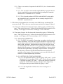
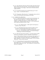
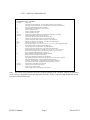
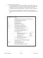
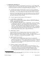
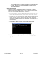
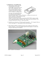
ELECTRONIC DEVICES INC.
P.O. BOX 15037, CHESAPEAKE, VA 23328. PH 757-421-2968 FAX 421-0518
DSTS-5A User's Manual
1. PACKING LIST
2.
3.
4.
5.
6.
7.
8.
9.
10.
DSTS-5A Manual
OVERVIEW
CONNECTING THE DSTS-5A TO A COMPUTER
CONNECTING A DEPTH SOUNDER TO THE DSTS-5A
OPERATING THE DSTS-5A
CALIBRATING THE DSTS-5A
SOFTWARE UPDATES
INSTALLING A CUSTOM LOAD
DSTS-5A SPECIFICATIONS
WARRANTY INFORMATION
Page 1
Doc 0612C12
DSTS-5A User's Manual
V1.42
1 PACKING LIST
1.1 The following items are included with the DSTS-5A:
1.1.1 Power transformer. A 9VDC 300mA wall plug power adapter is supplied.
Nominal power requirements are 8 to 12 volts at 200 mA.
1.1.2 A CD with software for controlling, calibrating, and updating the DSTS-4A.
1.1.3 A user's manual.
2 OVERVIEW
2.1 The DSTS-5A is a computer controlled depth sounder test set with fish echo emulation.
All functions such as reply level, depth, and width for the fish and bottom echoes are
controlled by data sent through the RS-232 port. The included program “DSTS-5A
Vx.xx.exe” or any terminal program may be used to control the DSTS-5A.
2.2 OPERATING THE DSTS-5A WITHOUT A COMPUTER
2.2.1 When powered up without the RS-232 connection the DSTS-5A will operate in
the Q-mode, allowing a depth sounder to be evaluated based on the transmitter
power and receiver sensitivity. The Q-mode generates an echo based on
transmitted power and depth. The depth is incremented by one foot and the reply
level is decreased each time the depth sounder transmits a pulse. As the depth
increases a point will be reached where the echo is no longer received. The quality
of the depth sounder can be read from the maximum depth reading before the echo
is lost.
3 CONNECTING THE DSTS-5A TO A COMPUTER
3.1 To install the supplied software, copy the file “DSTS-5A Vx.xx.exe”to a directory of
your choice. To run the
program, click on it and it
will launch. You must have a
serial port or USB/serial
adapter to use this program.
3.2 Connect the DSTS-5A to the
computer using a standard 9
pin RS-232 cable. Connect
the wall transformer power
supply. Status LED 2 will
light for six seconds and the
status LED's will sequence
one time. After power-up the
status LED 3 will glow and
pulse at a one-second rate indicating the DSTS-5A is ready for operation.
DSTS-5A Manual
Page 2
Doc 0612C12
3.3 Run the “DSTS-5A Vxxx.exe” program. If the com port and RS-232 connection are
correct, The DSTS-5A control panel program will open as shown. The input
frequency, width, period, and amplitude display zero until a pulse is received from the
depth sounder. To verify the connection, click the “reset” button. If the connection is
good, the software version will appear briefly in the input frequency display box.
4
CONNECTING A DEPTH SOUNDER TO THE DSTS-5A
4.1 Connect a depth sounder to the IN/OUT connector. Do not connect depth
sounder to the Trig Out connector or the DSTS-5A will be damaged. If the
depth sounder has a balanced output, one of the two inner wires will need to be
connected to the shield and grounded. Consult the manufacturers manual to determine
if one wire and the shield can be used as ground without damaging the depth sounder.
If you are unsure of the correct
connections for a balanced output,
use the EDI BAL-550 accessory.
The BAL-550 is a balanced-tounbalanced transformer that has
connections for the shield and two
wires. The output of the BAL-550
connects to the DSTS-5A.
4.1.1 Apply power to the depth
sounder. When the sounder
transmits, the red status LED
will blink indicating that a
pulse has been received.
4.1.2 The input characteristics of the received pulse are displayed on the upper group
of boxes and transmitted echo signals are displayed in the lower group. The results
are updated each time the DSTS-5A receives a pulse or once a second if no pulse
has been received. If the depth sounder is disconnected, the input pulse
characteristics will still display and will not change until a new pulse is received.
Pressing the “reset” button will reset the DSTS-5A and clear the input group of
displays.
5 OPERATING THE DSTS-5A
5.1 SETTING THE DEPTH AND REPLY LEVEL
The depth and reply level are set using the two track bars on the right side. Use the
mouse to move the slider to the desired depth. Fine adjustments are made using the
keyboard up and down arrow keys. For best results move the slider slowly.
5.2 SETTING THE FREQUENCY
5.2.1 Click the “Auto” button below the frequency track-bar to put the DSTS-5A in the
manual frequency mode. The check mark will disappear indicating that the DSTS
is in the manual frequency mode. Use the mouse to move the slider to the desired
frequency. Fine adjustments are made using keyboard up and down arrow keys.
DSTS-5A Manual
Page 3
Doc 0612C12
5.3 SETTING THE WIDTH
5.3.1 Click the “Auto” button below the frequency track-bar to put the DSTS-5A in the
manual width mode. The check mark will disappear indicating that the DSTS is in
the manual width mode. Use the mouse to move the slider to the desired frequency.
Fine adjustments are made using keyboard up and down arrow keys.
5.4 RESTORING THE AUTO TRACK MODES
5.4.1 To put the DSTS-5A into the tracking frequency mode, click the “Auto” button
to restore the check mark. The DSTS-5A will then generate reply pulses with the
same frequency as the input pulse.
5.4.1.1 Note: Always use the auto-frequency mode when using a dual-frequency
sounder.
5.4.2 To put the DSTS-5A in the pulse width tracking mode, click the “Auto” button to
restore the check mark. The DSTS-5A will generate reply pulses that are 1.6 times
wider than the input pulse width.
5.4.2.1 Note: Some depth sounders require that the auto-width mode is on
(checked) to operate correctly.
5.5 USING A TERMINAL PROGRAM WITH THE DSTS-5A TO ACCESS
ADDITIONAL FUNCTIONS
5.5.1 The DSTS-5A can be used with the supplied terminal program,
DSTS_terminal.exe. To start the EDI DSTS-5A Terminal Program, run the file
DSTS_terminal.exe any supply the active com port when requested. If using a
different terminal program or Window's Hyper Terminal the parameters should be
set for 9600 Baud, 8-bit data, no parity, one stop-bit. Flow control should be set to
none.
DSTS-5A Manual
Page 4
Doc 0612C12
5.5.1.1 There are two modes of operation for the DSTS-5A, the -4A mode and the
-5A mode.
5.5.1.1.1 The -5A mode is used with the supplied Window's program and can
also be controlled from any terminal program by sending the commands
detailed in the “Command List for -5A Mode”.
5.5.1.1.2 The -4A mode emulates a DSTS-4A with the EAB-3 option and is
only intended for use by customers who are currently using the DSTS4A/EAB-3 in production test.
5.6 The velocity of propagation for a new unit is set to 4800 feet per second and 1500
meters per second. These values are stored in eeprom and may be changed if desired.
5.6.1 For metric calibration first choose the metric mode by typing “cm”followed by
'enter'. Then type a lower case 'v' followed by the desired Vprop in meters/sec. For
example, to set Vprop to 1502 meters/ second type “v1502” and 'enter'.
5.6.2 For setting Vprop in feet first choose the foot mode by typing “cf”followed by
'enter'. Then type a lower case 'v' followed by the desired Vprop in meters/sec. For
example, to set Vprop to 4915 feet/second type “v4915” and 'enter'.
5.6.2.1 FISH ECHO GENERATION
5.6.2.1.1 The DSTS-5A is capable of generating a secondary echo between the
surface and bottom. This echo can be used to simulate an echo from a fish
or other object above the bottom and will be referred to as a fish echo. The
depth, width, amplitude, duration and arch shape of the fish echo can be
set. The duration of the fish echo is set by specifying the number of echoes
that the fish will generate as it passes under the transducer. A more realistic
fish echo can be generated by specifying a depth increment. The depth of
the fish echo is decreased for half the duration then increased for the
remainder of the duration. If the increment is set to zero the fish echo will
remain at a constant depth during its duration.
5.6.2.1.2 SETTING UP A TYPICAL FISH ECHO
5.6.2.1.2.1 Set the bottom depth to 25 feet by typing “d250 'enter'”. Set the
fish depth to 23 feet by typing “D230 'enter'”. Set the fish echo off time
to 20 pulses by typing “e20 'enter'”. Set the fish on time to 3 pulses by
typing “E3 'enter'” and the fish echo will appear for 3 pulses every
twenty pulses and repeat until disabled by typing “e 'enter”.
5.6.2.1.2.2 The amplitude of the fish echo can be set using the “L”
command.
DSTS-5A Manual
Page 5
Doc 0612C12
5.6.2.1.2.3 The width of the fish echo tracks the width of the pulse from the
depth sounder in the auto-track mode. It can be manually set using the
'Wxxxx' command. For example, “W200 'enter'”will fix the fish echo
width at 200 uSec.
5.6.2.1.2.4 To make the fish echo stay on continuously type “E 'enter' ”.
Type “e 'enter' ” to turn the fish echo off.
5.6.2.1.2.5 To generate a fish arch use the “i” command to enter an value in
tenths of the selected units representing the arch height.
5.6.2.1.3 CHIRP ECHO OPERATION
5.6.2.1.3.1 A chirp can be generated as a reply for the for the bottom echo.
This chirp is a linear frequency vs. time type. Inputs are the start
frequency, frequency step, step size, and the dwell time for the
frequency step. When the bottom echo occurs, it will sweep from the
start frequency through the number of steps.
5.6.2.1.3.1.1 The ending frequency will be equal to start frequency +
(number of steps * step size).
5.6.2.1.3.1.2 The duration of the chirp will be the number of steps *
dwell time. Note that minimum dwell time is about 5 uSec.
5.6.2.1.3.1.2.1 The dwell time is dependent on other factors such as
frequency so for maximum accuracy we recommend using an
oscilloscope to check the echo duration.
5.6.2.1.3.2 Enter the chirp menu by typing 'h'. A sub-menu appears and the
dwell time, start frequency, step size, and number of steps may be
entered. When the desired values have been entered type uppercase 'X'
to leave the chirp sub-menu and return to the -5A command menu so
depth, amplitude, etc. can be set. Note that typing 'X' does not stop the
chirp mode, it only exits the sub-menu.
5.6.2.1.3.3 To stop the chirp echo mode and return to normal operation,
type an uppercase 'H'. To re-start the chirp type 'h' and the previously
entered chirp settings will be used. These settings are not retained when
the power is turned off.
DSTS-5A Manual
Page 6
Doc 0612C12
5.6.2.2 DSTS-5A COMMAND LIST
Command List for -5A Mode
LETTER
a
A
b
B
cf
cF
cm
dxxxxxx
Dxxxxxx
e
exx
E
Exx
fxxxxx
Gx
h
H
i
l
L
p
P
~~~
r
s
S
t
v
wxxxxx
Wxxxxx
x
?
FUNCTION
Sets width Auto Track mode on. Turns off when a width is sent to the DSTS.
Sets frequency Auto Track mode on. Turns off when a frequency sent to the DSTS.
Sets normal (pulsed output) mode of operation.
Sets output signal to continuous wave (CW mode).
Sets the calibration to feet.
Sets the calibration to Fathoms.
Sets the calibration to meters.
Sets the bottom depth in tenths of the selected units, feet, meters, or fathoms.
Sets the fish depth in tenths of the selected units.
Turns off the fish echo mode. Returns only bottom echo.
The fish echo will be off for xx pulses from the depth sounder.
Turns on the fish echo mode. Returns two echoes, fish and bottom.
The fish echo will be on for xx pulses. Use with exx for repeating fish.
Sets the reply frequency in 10 Hz units.
Sets reply pulse stretch. X = 0,1,2,3,4 for 0.8, 1.0, 1.2, 1.4, or 1.6 times input pulse width.
Enters the chirp mode sub-menu and starts chirp reply.
Stops the chirp echo mode and returns to normal operation.
Sets the increment for the fish echo arch in tenths of the selected units.
Sets the bottom echo reply level in 0.3 dB steps, 0 to 255 max. 255 = 50 mV rms.
Sets the fish echo reply level in 0.3dB steps, 0 to 255 max. 255 = 50 mV rms.
Inserts additional 10 dB attenuation to reply level.
Removes additional 10 dB attenuation. Default condition.
Resets the DATA-5A hardware and software.
Resets and re-initializes the frequency averaging filter.
Stops auto data transmission from occurring. Data only sent when 'enter' is pressed.
Start auto data transmission. All input/output parameters are sent.
Test mode. Steps attenuator , sweeps frequency and voltmeter calibration.
Sets and stores the velocity of propagation in feet or meters per second.
Sets the bottom echo width in microseconds.
Sets the fish echo width in microseconds.
Enters the -4A mode of control.
Sends a simple menu of all commands to the terminal.
Note: The velocity of propagation as set in the -5A mode will apply to the -4A mode. There is no provision to
set the velocity of propagation while operating in the -4A mode. Limits to Vprop are 4000 to 6000 feet/second
and 1000 to 2000 meters/second.
DSTS-5A Manual
Page 7
Doc 0612C12
5.7 OPERATING IN THE -4A MODE
5.7.1 The-4A mode performs exactly like the DSTS-4A with the EAB-3 option. All
commands are the same. To enter the -4A mode of operation type ‘x’ followed by
the ‘enter’ key. Once in the -4A mode use the -4A commands. A list of the
commands is attached. In addition typing ‘?’ will bring up a menu of commands.
5.7.2 Single character commands such as 'A' do not need to be followed by enter.
Multiple character commands such as 'cf' or 'd2345' must be followed by the 'enter'
key.
Command List for -4A Mode
LETTER
a
A
b
B
C
cf
cF
cm
cR
cr
dxxxx
Dxxxx
e
E
fxxxx
i
l
m
o
r
R
v
wxxxxx
Wxxxxx
x
X
?
DSTS-5A Manual
FUNCTION
Sets width Auto Track mode on. Turns off when a width is sent to the DSTS.
Sets frequency Auto Track mode on. Turns off when a frequency sent to the DSTS.
Sets normal (pulsed output) mode of operation.
Sets output signal to continuous wave (CW mode).
Checks 50 kHz clock frequency.
Sets the calibration to feet.
Sets the calibration to Fathoms.
Sets the calibration to meters.
Extend Depth range to 9999 FT/FM/MT.
Reduce Depth range to 999.9 FT/FM/MT.
Sets the bottom depth in tenths of the selected units.
Sets the fish depth in tenth’s of the selected units.
Turns off the fish echo mode. Returns one bottom echo.
Turns on the fish echo mode. Returns two echoes.
Sets the reply frequency in 100 Hz units.
Returns DSTS data on input pulse parameters in this order:
Frequency, width, period, P-P voltage.
A typical string is 503,192,107,540. Leading 0's are not sent.
Sets the reply level in .3 dB steps, 0 to 255 max.
Returns DSTS modes in this order:
Calibration
0=ft, 1=fm, 2=mt
Number of processed pulses received since reset
0-255
Bottom echo or fish with bottom echo
bot or fsh
Auto width Track or manual
awt or mwt
Auto frequency Track or manual
aft or mft
CW or pulsed output
cwo or pul
Filter settled or not settled.
set or nst
A typical string is 0,bot,73,awt,aft,pul,set
Returns DSTS data on output pulse parameters in this order:
Frequency, width, depth, reply level.
Resets tracking gate and adaptive filters for frequency acquisition.
Resets the DSTS to power up default mode without exiting RS-232.
Reports the software version.
Sets the bottom echo width in microseconds. .
Sets the fish echo width in microseconds.
Enters the remote mode of control.
Exits the remote mode and return DSTS to normal operation.
Sends a simple menu of all commands to the terminal.
Page 8
Doc 0612C12
6 CALIBRATING THE DSTS-5A
6.1 The load resistor can change if overheated by too much power. A large change in the
resistance will cause the voltage and reply readings on a depth sounder to change. The
load resistor should be checked any time abnormal readings are experienced.
6.1.1 Check the load resistance with the DSTS-5A power off. Place an ohmmeter
across the IN/OUT connector. The resistance for the factory installed load should
be 582 ohms +/- 10%. The resistance of a custom load at the IN/OUT connector
should read 22 ohms higher than the value of the installed load resistor. If the load
is out of spec, the unit should be taken apart and the load resistor replaced before
any further calibration or checks are done.
6.1.2 Run the supplied terminal program, DSTS_terminal.exe.
6.1.3 VOLTMETER CALIBRATION
Caution—Do not perform this procedure without a EDI DSTS calibrator
or other comparable pulse source.1
6.1.3.1 The volt meter calibration is in the “extended menu”. Type 't' to enter the
extended menu. Then type 'c' to start the voltmeter calibration routine. Connect
the EDI DSTS calibrator or other comparable pulse source to the IN/OUT
connector. After the indicated voltage readings have settled down, type in the
correct input pulse voltage in volts peak-to-peak and press 'enter'. A calibration
factor will be generated and stored in eeprom. Press the reset button and check
that the voltage reads correctly. If not, repeat the calibration.
6.1.4 FREQUENCY CHECK
Connect the DSTS-5A to a frequency counter and press the reset button. Set the
output to continuous by typing ‘B’ followed by ‘enter’. Set output level to
maximum by typing l255. Set the frequency to 100 KHz by typing f10000 followed
by ‘enter’. The frequency counter must read 100,000Hz +/- 10 Hz.
6.1.5 REPLY AMPLITUDE CHECK
6.1.5.1 Connect a scope (1 megohm input required) directly to the IN/OUT
connector with a short (< 3ft) cable. Set the frequency to 100 KHz (f10000) and
the level to maximum (l255). The voltage must read 140 mV p-p +/- 7 mV p-p.
This is a fixed factory setting and will not change unless the DSTS-5A has been
damaged by a severe overload.
6.1.6 OPTIONAL REPLY ATTENUATOR CHECK
6.1.6.1 Connect the DSTS-5A IN/OUT connector to a spectrum analyzer. Set
various levels to make sure the attenuator tracks properly. Note that the output
on the analyzer will be low because the 50 ohm input impedance of the
spectrum analyzer loads down the DSTS-5A output. If a high impedance
(>=100,000 ohm) probe is available, the readings will be correct and a level of
1 The EDI DSTS Calibrator produces a 400 volt p-p pulse burst with a frequency of 204.8 KHz, length of 325 uSec,
and a period of 80 mSec. Droop is less than 10 percent.
DSTS-5A Manual
Page 9
Doc 0612C12
255 will produce 50 mV rms. Each decrease in the level will reduce the output
by 0.3 dB. The object is to verify that the attenuator is operating properly.
There are no adjustments.
7 SOFTWARE UPDATES
7.1 The DSTS-5A software can be updated via the RS-232 connection. As software
features are added, periodic update files may be sent via email. They can be installed
in the DSTS-5A by using the supplied program, “progdsts.exe”.
7.1.1 Put the progdsts.exe, update.bat, and the updated DSTS-5A.hex file in the same
directory. The illustrations assume the program and hex file are in the c:\ directory.
7.1.2 Press the reset (RST) button on the DSTS-5A and immediately run the update.bat
program. Note that after a RST, status led 2 stays on 5 seconds, then goes off.
You must start the update.bat program while the status led 2 is on for the update to
work successfully.
7.1.3 If the update is running successfully you will see the following screen:
7.1.4 After the update, the above screen will close and the DSTS-5A will begin
operating with the new software. It is not necessary to reset the DSTS-5A after an
update.
DSTS-5A Manual
Page 10
Doc 0612C12
8 INSTALLING A CUSTOM LOAD
8.1 Disassemble the DSTS-5A by first
removing the hex nut from the
IN/OUT BNC connector on the front
panel. Refer to illustration 1 and
remove the black plastic outer bezel
on the back panel (the side with the
RS-232 connector) by lifting it near
the center on the top and sides where
the catches are located. When the
bezel is off hold the DSTS-5A so the Illustration 1: Exploded view of DSTS-5A
IN/OUT connector is facing upwards housing.
and slide the back panel out of the
housing. Save the two lock washers located on the IN/OUT BNC connector and be
sure to replace them during re-assembly. Note: Do not remove the front bezel. The
front panel should not be removed, only the back panel.
8.2 Install the new load resistor, R24 and a parallel capacitance , C31 if required. Be sure
to move the jumper, J5, to the position closest to the front panel.
8.3 Re-assemble the DSTS-5A making sure the two lock washers are in place on the
IN/OUT connector. If necessary bend the ground contact slightly so it contacts the
front panel when the unit is assembled.
Photo 1: DSTS-5A Circuit Board.
DSTS-5A Manual
Page 11
Doc 0612C12
9 DSTS-5A SPECIFICATIONS
Parameter
Input frequency
Input width
Input period
Input voltage
Min input level
Output frequency
Output width
Echo depth
Output level
Vprop ft, fm
Vprop mtrs
Range
2.0 to 1200 KHz2
104 to 20,000 μs
10 to 9999 ms
50 to 2500 Vp-p
506 Vp-p
2.0 to 2000.00 KHz
10 to 20,000 μs
1 to 100,000 ft/fm/mt
2uV to 50,000uV
4800 to 5000 f/s
1460 to 1530 m/s
Resolution
10 Hz
0.1 μs
1 ms
2 Vp-p
N/A
10 Hz
0.1 μs
0.1 unit
0.3dB
1 f/s
1 m/s
Accuracy
±.02% ±20 Hz3
±.02% ±2 cycles
±.02% ±1 ms
±10 Vp-p ±5%5
±10 Vp-p
±.01%
±.02%
±.01%
±1.0 dB7
±.01%
±.01%
Depth jitter
Baud rate
less than 50 nSec maximum at 1 second depth delay.
9600, 8 bits, no parity, no handshake.
Power requirements: 9 VDC @ 200 mA.
Size and Weight:
6" W by 7"D by 3.5"H. Shipping Wt, 2.1 Lbs.
10 WARRANTY INFORMATION
Unit will be repaired free of charge for one year from date of purchase providing there is no
water damage or other evidence of improper use or handling. Purchaser must ship unit
prepaid to address below; EDI will pay the return freight.
For repair, please enclose a note describing the problem and ship to:
ATTN: Service Department
Electronic Devices, Inc.
3140 Bunch Walnuts Road
Chesapeake, VA 23322
USA
Phone: 1-757-421-2968
2
3
4
5
6
7
Usable to > 2.0 Mhz with reduced amplitude accuracy.
Specified for pulse widths greater than 99 uS.
Input pulse must contain at least 4 cycles.
Measured at 200KHz, 400Vp-p with a 325 uSec pulse width.
At 50 Khz. Approximately 200 Vp-p at 1 Mhz.
At 800 Khz, -2dB at 1200 Khz
DSTS-5A Manual
Page 12
Doc 0612C12


![FLM HD18 [v08]](http://vs1.manualzilla.com/store/data/005664321_1-9e0d84f2b9cac33a4ebfb5904f0dafa1-150x150.png)