1
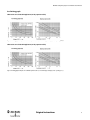
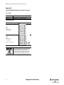
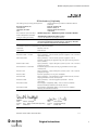
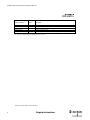
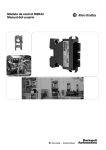
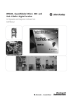
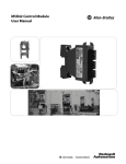
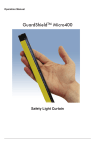
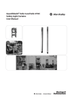
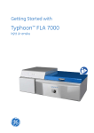
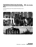
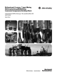
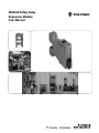
MSR45E Safety Relay
Expansion Module
User Manual
Important User Information
Because of the variety of uses for the products described in this publication, those responsible for the
application and use of this control equipment must satisfy themselves that all necessary steps have been
taken to assure that each application and use meets all performance and safety requirements, including
any applicable laws, regulations, codes and standards.
The illustrations, charts, sample programs and layout examples shown in the guide are intended solely for
purposes of example. Since there are many variables and requirements associated with any particular
installation, Rockwell Automation does not assume responsibility or liability (to include intellectual property
liability) for actual use based upon the examples shown in this publication.
Rockwell Automation publication SGI-1.1, Safety Guidelines for the Application, Installation and
Maintenance of Solid-State Control (available from your local Rockwell Automation sales office), describes
some important differences between solid-state equipment and electromechanical devices that should be
taken into consideration when applying products such as those described in this publication.
Reproduction of the contents of this copyrighted publication, in whole or part, without written permission
of Rockwell Automation, is prohibited.
Throughout this manual we use notes to make you aware of safety considerations:
WARNING
IMPORTANT
ATTENTION
Identifies information about practices or circumstances that can cause an explosion in
a hazardous environment, which may lead to personal injury or death, property
damage, or economic loss.
Identifies information that is critical for successful application and understanding of
the product.
Identifies information about practices or circumstances that can lead to personal
injury or death, property damage, or economic loss. Attentions help you identify a
hazard, avoid a hazard, and recognize the consequences.
SHOCK HAZARD
Labels may be on or inside the equipment (for example, drive or motor) to alert people
that dangerous voltage may be present.
BURN HAZARD
Labels may be on or inside the equipment (for example, drive or motor) to alert people
that surfaces may reach dangerous temperatures.
It is recommended that you save this user manual for future use.
MSR45E Safety Relay Expansion Module User Manual
Content
Approvals and Conformity
Approvals and Conformity . . . . . . . . . . . . . . . . . . . . . . . . 1
The safety approval, performed by TÜV Rheinland is available on
www.ab.com. The actual list of relevant safety data and applied standards
is given in these documents.
Introduction . . . . . . . . . . . . . . . . . . . . . . . . . . . . . . . . . . . . . 1
Special features . . . . . . . . . . . . . . . . . . . . . . . . . . . . . . . . . . . . . . . . . . . . . . 2
MSR42, MSR41 or MSR45E units can only
achieve their function as a safety
controller module, if the instructions
given in this instruction manual and the
within mentioned documents are exactly
followed, as well as consulting the valid
laws and regulations at the time of
installation. Should these instructions not
be carefully followed, serious injury or
death may occur. The installer or system
integrator is responsible for a safe
integration of this product. This
instruction manual is to be used in
conjunction with the MSR42, MSR41 and
MSR45E module. It must be kept
accessible together with the other
machine documentation during its entire
life cycle for all personnel responsible for
assembly, installation, operation and
maintenance.
Applications . . . . . . . . . . . . . . . . . . . . . . . . . . . . . . . . . . . . . 2
Typical applications . . . . . . . . . . . . . . . . . . . . . . . . . . . . . . . . . . . . . . . . . . 2
Application restrictions. . . . . . . . . . . . . . . . . . . . . . . . . . . . . . . . . . . . . . . 2
Dimensions . . . . . . . . . . . . . . . . . . . . . . . . . . . . . . . . . . . . . . . 2
Terminal Configurations . . . . . . . . . . . . . . . . . . . . . . . . . . 2
Connecting Hardware. . . . . . . . . . . . . . . . . . . . . . . . . . . . . 2
LED display elements . . . . . . . . . . . . . . . . . . . . . . . . . . . . . 2
MSR45E Expansion module . . . . . . . . . . . . . . . . . . . . . . . . . . . . . . . . . . 2
Selection tables . . . . . . . . . . . . . . . . . . . . . . . . . . . . . . . . . . 3
Accessories / Components. . . . . . . . . . . . . . . . . . . . . . . . . 3
Inspection and service . . . . . . . . . . . . . . . . . . . . . . . . . . . . 3
Inspections . . . . . . . . . . . . . . . . . . . . . . . . . . . . . . . . . . . . . . . . . . . . . . . . . . 3
Decommissioning. . . . . . . . . . . . . . . . . . . . . . . . . . . . . . . . . . . . . . . . . . . . 3
Product labels . . . . . . . . . . . . . . . . . . . . . . . . . . . . . . . . . . . . 3
Technical Data. . . . . . . . . . . . . . . . . . . . . . . . . . . . . . . . . . . . 4
Arc-limiting graph . . . . . . . . . . . . . . . . . . . . . . . . . . . . . . . . . . . . . . . . . . . 5
Appendix . . . . . . . . . . . . . . . . . . . . . . . . . . . . . . . . . . . . . . . . 6
Introduction
The MSR4x is a family of compact safety modules. The main controlling
module allows the connection and the control of the GuardShield
Micro400 safety light curtain systems (Figure 1). Depending on the
configuration, other safety components can also be connected and
monitored simultaneously.
EC Declaration of Conformity. . . . . . . . . . . . . . . . . . . . . . . 7
Expansion modules
Main module
Figure 1: MSR42 controller with all safety components which can be connected (depending
on individual configuration)
Both the MSR42 and MSR41 offer two safety PNP outputs. Additional
safety relay expansion modules can be applied for applications, which
require more outputs (MSR41 or 42) and/or dry contacts (MSR45e) to
switch loads. Up to three expansion modules can be controlled and daisy
chained to one main module.
In addition to the expansion relays, models are offered in special
configurations which are described in the appendix at the end of this
manual.
Original instructions
1
MSR45E Safety Relay Expansion Module User Manual
Note: The MSR45E safety relay expansion module is not a standalone
safety relay module. It can only be used in conjunction with either an
MSR41 or MSR42 control module.
Terminal Configurations
The safety output contact configuration of the MSR45E.
Snap control & expansion housing module together. Use ribbon cable to
electronically link devices.
Special features
The outstanding characteristics of the MSR42 and MSR41 controller:
• Category 4, PL e according EN ISO 13849-1
• Type 4 according EN 61496-1/-2
• SIL 3 according IEC 61508
• SIL CL 3 according EN 62061
• Short response times
• Up to 3 safety relay expansion modules per main module
• Adjustable stop delay time
• Different safety components suitable for connection (MSR42)
Type of Expansion module
Schematic
MSR45E
Safety Relay Expansion
Cat.-No. 440-P4NANAS
Figure 3: MSR45E Expansion module.
Applications
Connecting Hardware
Typical applications
MSR42 and MSR41 controller modules are developed and conceived for
typical applications like:
• Presses
• Robotic cells with automatic insertion
• Assembly lines
• Indexing tables
• Conveyor systems
• Automatic storage facilities
Main module + one Expansion module
Application restrictions
All MSR4x modules are not intended for application in explosive (EX)
or in radioactive environments.
Figure 4: Ribbon Cable for one expansion module. (Cat. No 440R-ACABL1)
Dimensions
The dimensions of the housing for MSR45E are illustrated in Figure 2.
110
111
95
Figure 5: Ribbon cable for two expansion modules.
125
LED display elements
22.5
Figure 2: Expansion module dimensions are the same for main module
2
MSR45E Expansion module
Only two LED is integrated in the MSR45E expansion modules (FSD):
Color LED "FSD"
Status
Green
Corresponding contacts of module are closed (active)
Red
Corresponding contacts of module are opened (not active, NC contact)
Original instructions
MSR45E Safety Relay Expansion Module User Manual
Color LED "FSD"
Status
Off
No power at main module or no internal bus
(e.g. no ribbon cable connection)
Inspections
The MSR45E modules have to be tested periodically – in accordance
with valid regulations - by qualified and trained personnel to discover
prohibited manipulations or unauthorized modifications.
Table 1
Decommissioning
Selection tables
Cat. No.
Controller / Expansion modules
440R-P221AGS
MSR41 Micro400 controller
440R-P226AGS-NNR
MSR42 Light Curtain multifunction safety controller
440R-P4NANAS
MSR45E 2C, Standard Safety Relay Expansion Module
Table 2
Accessories / Components
Cat. No.
Description
Ribbon Cable – connects two modules
The MSR45E modules can only be removed, when the machine or the
equipment is shut down completely and can no longer be operated
without tools. If a controller has to be disposed, it can be simply
dismantled. The separated materials can be recycled according to state of
the art technology and corresponding regulations of the country it was
used in.
Product labels
All the necessary safety information can be found on the product labels,
which can be found on every controller module (example):
440R-ACABL1
Ribbon Cable – connects three modules
440R-ACABL2
Figure 5: Product label MSR4E Expansion module
Ribbon Cable – connects four modules
440R-ACABL3
Terminal Block Kit - MSR42
440R-ATERM2P
Terminal Block Kit - MSR45E
440R-ATERM2C
Terminal Block Kit – MSR41
440R-ATERM1P
Table 3
Inspection and service
The MSR45E modules have no serviceable components.
Original instructions
3
MSR45E Safety Relay Expansion Module User Manual
Technical Data
Relay Outputs of Expansion Modules
General data
Nominal working mode
Continuous process
Temperature range
Environment temp.: 0 ... +55°C
Stock temp.: -25 ... +70°C
Enclosure rating according EN 60529
Housing
Terminals
Conductor connection:
6-pin terminal strip
Switch on delay after switching on
the power supply
<3s
Switch off delay after switching off
the power supply
< 40 ms
Safety Related Parameter
IP20
IP20
Wire cross section:
max 2.5 mm2
spring clamping technology
min. 12 mm ferrule or wire length
Quick mounting
Top hat rail 35 mm (EN 50022)
Net weight
MSR45E: 150 g
Housing dimensions
111 x 22,5 x 125 mm (incl. plugs)
Housing material
Polyamide
Vibration according to EN60068-2-6
Amplitude: 0.35 mm
Frequency: 10 … 55 Hz
Shock resistant according to EN 60068-2-29
Acceleration: 100 ms-2
Impulse length: 16 ms
Number of shocks: 1'000 per direction
Installation position
No restrictions
Approvals
TÜV, CE, cULus
6.0 E-9 1/h
Probability of a dangerous failure per hour 9.0 E-10 1/h
PFH
3.0 E-10 1/h
4.0 E-9 1/h
Weight and packaging
Dispatch packaging
280 mm x 200 mm x 70 mm
Dispatch weight
Net weight + 220 g
Relay Outputs of Expansion Modules
Max. number of expansion modules
3 per main module
Number of contacts
2NO, 3NO or 2NO1NC
Additional max. response time t(em) with UN
protective mode
≤ 6 ms
Contact type
Relay, force guided (EN 50205)
Contact material
AgSN02 + 0.2 μm AU plated
Min. switching capacity
0.06 VA
Max. switching capacity
250 V(AC) 8A, [AC1] = 2'000 VA
Min. switching current
10 mA
Max. switching current
8A
Max. switching voltage
2NO: AC 250V; DC 300V
3NO or 2NO1NC: AC 120V; DC 170V
Output nominal voltage
DC: see arc-limiting graph
2C:
Continuous current Ith
With simultaneous switching
With 1 expansion-module
With 2 or more exp.-modules
8 A (1 contact)
6 A (≥ 2 contacts)
4 A (≥ 2 contacts)
Switching capacity acc. DC 13
(EN 60947-5-1, 0.1 Hz, 24 V)
MSR45E:
6 A DC / 24 V
Switching capacity acc. AC 15
(EN 60947-5-1, 0.1 Hz, 220 V)
2NO: 3A AC / 230V
3NO or 2NO1NC: 3A AC / 120V
Electronic lifespan according
AC 15 at 2 A, 230 VAC
2C or 3C: 105 operating cycles
(EN 60947-5-1)
see graphics below (arc limiting graph)
Allowed switching capacity
2C or 3C: Max. 900 switching / h
Mechanical lifespan
106
4
Original instructions
MSR4x Main M. & MSR45e Ext & Micro400
MSR4x Main M.
MSR45E
Micro400
MSR45E Safety Relay Expansion Module User Manual
Arc-limiting graph
Characteristic curves for DC and AC applications (2C relay expansion module):
Figure 6: Arc-limiting graph and lifespan curve for MSR45E expansion modules (secure off switching, no standing arc, max. 1 operating cycle / s)
Characteristic curves for DC and AC applications (3C relay expansion module):
Figure 7: Arc-limiting graph and lifespan curve for MSR45E expansion modules (secure off switching, no standing arc, max. 1 operating cycle / s)
Original instructions
5
MSR45E Safety Relay Expansion Module User Manual
Appendix
Special MSR45E modules for existing customers.
Selection Table
Cat. No.
Controller / Expansion modules
445L-105938
MSR45E-3C 2NO1NC, special safety relay Expansion Module
445L-104860
MSR45E-3C 3NO, special safety relay Expansion Module
Terminal Configurations
Type of Expansion module
Schematic
MSR45E
3C 3NO
Safety Relay Expansion
Cat.-No. 445L-104860
MSR45E
2NO1NC
Safety Relay Expansion
Cat.-No. 445L-105938
NC contacts are not safety contacts
Figure 8: MSR45E Expansion modules.
The normally-closed contacts (NC) of an
expansion module may only be used for
status feedback from the machine
controller. They may not be used for any
safety function. Any integration with a
machine’s safety circuit is not allowed.
6
Original instructions
MSR45E Safety Relay Expansion Module User Manual
EC Declaration of Conformity
The undersigned, representing the manufacturer
Rockwell Automation, Inc.
2 Executive Dr.
Chelmsford, MA 01824
USA
Herewith declare that the Products:
Product identification (brand and
catalogue number/part number):
Product Safety Function
and the authorised representative established within the
Community
Rockwell Automation BV
Rivium 1e Straat, 23
2909 LE Capelle aan den IJssel
Netherlands
MSR4x Safety Base / MSR4xE Expander Controller Modules
Allen-Bradley 440R-P and 445L-1 Series
(reference the attached list of catalogue numbers)
The MSR4x safety base control devices and the MSR4xE extension modules
can be used in applications up to Safety Category 4 (EN 954-1)/ SIL3/SIL
CL3 (EN 61508 / EN 62061) and PL e (EN ISO 13849-1).
are in conformity with the essential requirements of the following EC Directive(s) when installed in accordance with
the installation instructions contained in the product documentation:
2006/42/EC
Machinery Directive
EMC Directive
2004/108/EC
and that the standards and/or technical specifications referenced below have been applied:
EN 61496-1:2004 + A1:2008
Safety of machinery – Electro-sensitive protective equipment – Part 1: General
requirements and tests
IEC 61496-2:2006
Safety of machinery – Electro-sensitive protective equipment – Part 2:
Particular requirements for equipment using active opto-electronic protective
devices (AOPD’s)
EN ISO 13849-1:2008
Safety of machinery – Safety-related parts of control systems – Part 1: General
principles for design
EN 61508 Parts 1-7:1998-2000
Functional safety of electrical/electronic/programmable electronic safetyrelated systems
EN 954-1:1997
Safety of machinery – Safety related parts of control systems – Part 1: General
principles for design
EN 50178:1997
Electronic equipment for use in power installations
EN 62061:2005
Safety of machinery – Functional safety of safety-related electrical, electronic
and programmable electronic control systems
EN 60204-1:2006
Safety of machinery – Electrical equipment of machines – General
requirements
EN 61000-6-4:2007
Electromagnetic compatibility (EMC) – Part 6-4: Generic standards –
Emission standard for industrial environments (Class A)
EN 61000-6-2:2005
Electromagnetic Compatibility (EMC) – Part 6-2: Generic standards –
Immunity for industrial environments
Manufacturer:
Authorised Representative in the Community:
Signature
Name:
Daniel L. Nachtigall
Position: Supv – Product Certification Engineering
Date:
01-Mar-2011
Signature
Name:
Viktor Schiffer
Position: Engineering Manager
Date:
08-Mar-2011
Document Control Number: SEN-0394-B-EN
Original instructions
1/2
7
MSR45E Safety Relay Expansion Module User Manual
Catalogue number 1
440R-P221AGS
440R-P226AGS-NNR
445L-104794-B***
440R-P4NANS
445L-1****
Series 2
Description
MSR41 base module
MSR42 base module
MSR42 base module customer configuration
MSR45E expander module
MSR45E expander module customer configuration
1) *Denotes characters representing options that do not impact the standards or directives cited on this DoC
2) If no series number is given, then all series are covered
Document Control Number: SEN-0394-B-EN
8
Original instructions
2/2
Technical Support / Technische Unterstützung / Assistance technique / Assistenza tecnica / Asistencia técnica
ENGLISH
DEUTSCH
FRANÇAIS
ITALIANO
ESPAÑOL
PORTUGUÊS
POLSKI
ČESKY
SVENSKA
NEDERLANDS
Installation of this product must not take place until the installer has obtained a copy of the manufacturer’s instructions in a language which he can understand.
This instruction sheet is available in multiple languages at http://rockwellautomation.com/literature.
Dieses Produkt darf erst installiert werden, wenn der Installateur eine Kopie der Instruktionen des Herstellers in der Sprache eingeholt hat, die er versteht.
Diese Instruktionen sind mehrsprachig erhältlich unter: http://rockwellautomation.com/literature.
Ce produit ne peut être installé avant l’obtention d’un duplicata des instructions du fabricant dans une langue compréhensible.
La fi che d’instructions est disponible en plusieurs langues depuis le lien http://rockwellautomation.com/literature.
Non si deve procedere all’installazione di questo prodotto fin quando l’installatore non abbia ottenuto una copia delle istruzioni del produttore in una lingua che
l’installatore possa capire. La presente scheda di istruzioni è disponibile in linguaggi multipli sul sito web http://rockwellautomation.com/literature.
Absténgase de instalar este producto a menos que el instalador disponga de un ejemplar de las instrucciones del fabricante en un idioma que pueda comprender.
En http://rockwellautomation.com/literature puede encontrar esta hoja de instrucciones en varios idiomas.
A instalação deste produto não pode ser efectuada até que o montador tenha obtido uma cópia das instruções do fabricante numa língua que ele compreenda.
Essa folha de instruções está disponível em diversas línguas em http://rockwellautomation.com/literature.
Nie należy przeprowadzać instalacji tego produktu aż do otrzymania przez montera instrukcji producenta w języku, który on rozumie.
Te karty z instrukcjami są dostępne w wielu językach na: http://rockwellautomation.com/literature.
Instalace tohoto výrobku nesmí proběhnout, dokud instalující osoba neobdrží pokyny výrobce v jazyce, kterému rozumí.
Tyto pokyny jsou k dispozici v několika jazycích na http://rockwellautomation.com/literature.
Denna produkt får inte installeras förrän installatören har skaff at ett exemplar av tillverkarens instruktioner på ett språk som han/hon förstår.
Detta instruktionsblad fi nns på fl era språk på http://rockwellautomation.com/literature.
Het product mag pas worden geïnstalleerd wanneer de monteur beschikt over een exemplaar van de instructies van de fabrikant in een voor hem begrijpelijke
taal. Dit instructieblad is in diverse talen verkrijgbaar op http://rockwellautomation.com/literature.
: http://rockwellautomation.com/literature
: http://rockwellautomation.com/literature
http://rockwellautomation.com/literature
БЪЛГАРСКИ
EESTI
SUOMI
ΕΛΛΗΝΙΚΆ
MAGYAR
ÍSLENSKA
LATVIEŠU VALODA
LIETUVIRŠKAI
MALTI
NORSK
ROMÂNĂ
SLOVENSKY
SLOVENŠČINA
TÜRKÇE
Това устройство не трябва да се монтира, докато монтажника не разполага с инструкциите на производителя, на разбираем за него език.
Инструкциите за монтаж ще намерите на различни езици в http://rockwellautomation.com/literature.
Selle toote installatsioon ei tohi toimuda enne kui installeerija on omandanud koopia tootja instruktsioonidega keeles mida ta ise valdab.
Instruktsioonid erinvates keeltes on saadaval siin: http://rockwellautomation.com/literature.
Tämä tuote voidaan asentaa vasta kun asentaja on hankkinut valmistajan ohjeet kielellä, jota hän ymmärtää.
Erikieliset ohjeet ovat ladattavissa sivustolta http://rockwellautomation.com/literature.
Εγκατάσταση του προϊόντος αυτού δεν πρέπει να γίνει πριν ο εγκαταστάτης προμηθευθεί αντίτυπο οδηγιών του κατασκευαστή σε γλώσσα που ο ίδιος καταλαβαίνει.
Το εγχειρίδιο αυτό διατίθεται σε διόφορες γλώσσες στη διεύθυνση http://rockwellautomation.com/literature.
Ez a termék csak akkor helyezhető üzembe, ha az üzembehelyezést végző személy rendelkezésére áll a gyártó használati utasítása az általa ismert nyelven.
Az utasítás több nyelven megtalálható itt: http://rockwellautomation.com/literature
Uppsetning á þessari vöru má ekki eiga sér stað fyrr en sá sem annast uppsetninguna hefur fengið afrit af leiðbeiningum framleiðanda á því tungumáli sem hann
þekkir. Leiðbeiningarpésinn er tiltækur á mörgum tungumálum og er hægt að ná í hann hér: http://rockwellautomation.com/literature
Šī ražojuma uzstādīšanu nedrīkst veikt, pirms uzstādītājs nav saņēmis ražotāja instrukcijas tādā valodā ko viņš saprot.
Šo instrukciju lapiņu var saņemt daudzās valodās no vietnes http://rockwellautomation.com/literature
Šito produkto įrengimas negali būti vykdomas tol, kol įrengėjas neturės gamintojo instrukcijų kopijos ta kalba, kurią jis supranta.
Instrukciją galima rasti įvairiomis kalbomis tinklapyje http://rockwellautomation.com/literature
L-installazzjoni ta’ dan il-prodott mgħandux isir qabel ma l-installatur jakwista kopja tal-istruzzjonijiet tal-manifattur f’lingwa li tista’ tiftiehem.
Il-karta tal-istruzzjonijiet hija disponibbli f’ħafna lingwi f’http://rockwellautomation.com/literature.
Dette produktet må ikke installeres før installatøren har bruksanvisningen på et behersket språk.
Dette instruksjonsarket kan fås i fl ere språk på http://rockwellautomation.com/literature.
Produsul nu trebuie să fi e instalat până când cel care instalează produsul nu a obţinut o copie a manualului de utilizare , în limba pe care o poate înţelege.
Aceste instrucţiuni sunt valabile în mai multe limbi la adresa http://rockwellautomation.com/literature.
Inštalácia tohto výrobku nesmie prebehnúť, dokiaľ inštalujúca osoba nedostane pokyny výrobca v jazyku ktorému rozumie.
Tieto pokyny sú k dispozícii v niekoľkých jazykoch na http://rockwellautomation.com/literature.
Tega izdelka se ne sme nameščati, če si oseba, ki ga namešča, ni priskrbela izvoda proizvajalčevih navodil v jeziku, ki ga razume.
Ta list z navodili v številnih jezikih je na razpolago na http://rockwellautomation.com/literature.
Bu ürünün kurulmasının, ürünü kuracak kişinin üreticinin hazırladığı talimatların bir kopyasını, ki bu talimatlar bu kişinin anlayacağı bir dilde olacaktır,
elde edene kadar gerçekleşmemesi gerekir. Bu talimatlar pek çok dilde şu web-sayfasında mevcuttur: http://rockwellautomation.com/literature
GuardShield is a trademark of Rockwell Automation, Inc.
Guardmaster is a registered trademark of Rockwell Automation, Inc.
www.rockwellautomation.com
Power, Control and Information Solutions Headquarters
Americas: Rockwell Automation, 1201 South Second Street, Milwaukee, WI 53204 USA, Tel: (1) 414.382.2000, Fax: (1) 414.382.4444
Europe/Middle East/Africa: Rockwell Automation, Vorstlaan/Boulevard du Souverain 36, 1170 Brussels, Belgium, Tel: (32) 2 663 0600, Fax (32) 2 663 0640
Asia Pacific: Rockwell Automation, Level 14, Core F, Cyberport 3, 100 Cyberport Road, Hong Kong, Tel: (852) 2887 4788, Fax: (852) 2508 1846
10000172479 Ver00
CSA 107 179
April 2011
Copyright ©2011 Rockwell Automation, Inc. All Rights Reserved. Printed in USA.