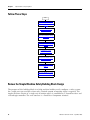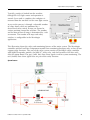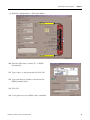
1
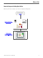
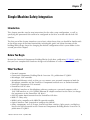
Simple Machine Safety (E-stop, Door Switch,
Light Curtain) Connected Components Building
Block
PowerFlex® 40P, MicroLogix™ 1400, GuardShield™ Micro400 Light Curtains
Quick Start
Important User Information
Solid state equipment has operational characteristics differing from those of electromechanical equipment. Safety Guidelines
for the Application, Installation and Maintenance of Solid State Controls (publication SGI-1.1 available from your local Rockwell
Automation sales office or online at http://www.rockwellautomation.com/literature/) describes some important differences
between solid state equipment and hard-wired electromechanical devices. Because of this difference, and also because of the
wide variety of uses for solid state equipment, all persons responsible for applying this equipment must satisfy themselves that
each intended application of this equipment is acceptable.
In no event will Rockwell Automation, Inc. be responsible or liable for indirect or consequential damages resulting from the use
or application of this equipment.
The examples and diagrams in this manual are included solely for illustrative purposes. Because of the many variables and
requirements associated with any particular installation, Rockwell Automation, Inc. cannot assume responsibility or liability for
actual use based on the examples and diagrams.
No patent liability is assumed by Rockwell Automation, Inc. with respect to use of information, circuits, equipment, or software
described in this manual.
Reproduction of the contents of this manual, in whole or in part, without written permission of Rockwell Automation, Inc., is
prohibited.
Throughout this manual, when necessary, we use notes to make you aware of safety considerations.
WARNING
Identifies information about practices or circumstances that can cause an explosion in a hazardous environment,
which may lead to personal injury or death, property damage, or economic loss.
IMPORTANT
Identifies information that is critical for successful application and understanding of the product.
ATTENTION
Identifies information about practices or circumstances that can lead to personal injury or death, property damage,
or economic loss. Attentions help you identify a hazard, avoid a hazard, and recognize the consequence
SHOCK HAZARD
Labels may be on or inside the equipment, for example, a drive or motor, to alert people that dangerous voltage may
be present.
BURN HAZARD
Labels may be on or inside the equipment, for example, a drive or motor, to alert people that surfaces may reach
dangerous temperatures.
Allen-Bradley, Rockwell Automation, TechConnect, PowerFlex, MicroLogix, PanelView, DriveTools, DriveGuard, DriveExplorer, SensaGuard, and GuardShield are trademarks of Rockwell
Automation, Inc.
Trademarks not belonging to Rockwell Automation are property of their respective companies.
Where to Start
Connected Components Building Block Outline
Follow the path below to complete your connected components building block.
Connected Components
Building Blocks, publication
CC-QS001
Chapter 1 Simple Machine
Safety Integration
Chapter 2 System
Validation and Application
Tips
3Publication CC-QS011A-EN-P - September 2009
3
Where to Start
4
Publication CC-QS011A-EN-P - September 2009
Table of Contents
Preface
About This Publication . . . . . . . . . . . . . . . . . . . . . . . . . . . . . 7
Conventions . . . . . . . . . . . . . . . . . . . . . . . . . . . . . . . . . . . . . 7
Additional Resources. . . . . . . . . . . . . . . . . . . . . . . . . . . . . . . 8
Chapter 1
Simple Machine Safety
Integration
Introduction . . . . . . . . . . . . . . . . . . . . . . . . . . . . . . . . . .
Before You Begin . . . . . . . . . . . . . . . . . . . . . . . . . . . . . .
What You Need . . . . . . . . . . . . . . . . . . . . . . . . . . . . . . .
Follow These Steps . . . . . . . . . . . . . . . . . . . . . . . . . . . . .
Review the Simple Machine Safety Building Block Design
Understanding the Safety Function. . . . . . . . . . . . . . . . . .
Check Drive Hardware Settings . . . . . . . . . . . . . . . . . . . .
Install Safe-Off Option Board to the PowerFlex 40P Drive
Assemble the System Components . . . . . . . . . . . . . . . . . .
Configure the MSR42 Safety Controller . . . . . . . . . . . . . . .
Adjust Drive Parameters . . . . . . . . . . . . . . . . . . . . . . . . .
Specify the Number of E-Stops and Door Switches . . . . . .
.
.
.
.
.
.
.
.
.
.
.
.
.
.
.
.
.
.
.
.
.
.
.
.
. 9
. 9
. 9
10
10
12
13
13
13
14
17
25
Chapter 2
System Validation and Application Introduction . . . . . . . . . . . . . . . . . . . . . . . . . . . . . . . . . . . . 27
Before You Begin . . . . . . . . . . . . . . . . . . . . . . . . . . . . . . . . 27
Tips
What You Need . . . . . . . . . . . . . . . . . . . . . . . . . . . . . . . .
Follow These Steps . . . . . . . . . . . . . . . . . . . . . . . . . . . . . .
Configure and Validate PanelView Component Terminal to
MicroLogix Controller Communication . . . . . . . . . . . . . . . .
Test Simple Safety Application Functionality. . . . . . . . . . . .
5Publication CC-QS011A-EN-P - September 2009
. 27
. 28
. 28
. 29
5
Table of Contents
6
Publication CC-QS011A-EN-P - September 2009
Preface
About This Publication
This quick start is designed to provide a simple, reusable implementation of a low-cost safety
system. Its aim is to demonstrate a structured template for the machine safety designer. The
Simple Machine Safety Building Block is an add-on component, which can be used with some
existing projects.
IMPORTANT
Use the Simple Machine Safety Connected Components Building Block Quick Start in conjunction
with the Connected Components Building Blocks Quick Start, publication CC-QS001.
Refer to Additional Resources on page 8 for a listing of quick starts.
To assist in the design and installation of your system, application files and other information are
provided on the Connected Components Building Blocks Overview CD, publication CC-QR001.
The CD provides bills of materials (BOM), CAD drawings for panel layout and wiring, control
programs, Human Machine Interface (HMI) screens, and more. With these tools and the built-in
best-practices design, the system designer is free to focus on the design of their machine control
and not on design overhead tasks.
The beginning of each chapter contains the following information. Read these sections carefully
before beginning work in each chapter:
• Before You Begin - This section lists the steps that must be completed and decisions that
must be made before starting that chapter.
• What You Need - This section lists the tools that are required to complete the steps in the
current chapter. This includes, but is not limited to, hardware and software.
• Follow These Steps - This illustrates the steps in the current chapter and identifies which
steps are required to complete the examples.
Conventions
Convention
Meaning
Example
Check or uncheck
To activate or deactivate a checkbox.
Check Disable Keying.
Click
Click the left mouse button once while the cursor is positioned on
object or selection to initiate an action.
Click Browse.
Double-click
Click the left mouse button twice in quick succession while the cursor
is positioned on object or selection to initiate an action.
Double-click the application icon.
Expand
Click the + to the left of a given item /folder to show its contents.
Expand 1768 Bus under I/O Configuration.
Right-click
Click the right mouse button once while the cursor is positioned on
object or selection.
Right-click the 1768 Bus icon.
Select
Using the mouse to highlight a specific option.
Select the New Module folder.
Press
Pressing a specific key on the keyboard or button on a touchscreen.
Press Enter.
>
Use this symbol to indicate the sub-menu name.
Choose File > Menu > Options.
‘Project’
Refers to the application on both the controller side and the PanelView component side.
7Publication CC-QS011A-EN-P - September 2009
7
Preface
Additional Resources
8
Resource
Description
Connected Components Building Blocks Quick
Start, publication CC-QS001
Provides information on how to select products and gain access to panel and wiring
information
Connected Components Building Blocks
Overview CD, publication CC-QR001
Provides files for the Connected Components Building Blocks
Position Control Connected Components
Building Block Quick Start, publication
CC-QS003
Provides information installing and setting up the PowerFlex 40P drive parameters with
the pre-configured RSLogix 500 program that controls you base system including
application tips, as well as implementing the drive parameter backup and restore
functionality
MicroLogix 1400 Controller User Manual,
publication 1766-UM001
Provides information on using the MicroLogix 1400 Programmable Controller
PowerFlex 40P Adjustable Frequency AC Drive
User Manual, publication 22D-UM001
Provides information on installing the PowerFlex 40P drive, including wiring and
parameter setup
DriveGuard Safe-Off Option (Series B) for
PowerFlex 40P and PowerFlex 70 AC Drives User
Manual, publication PFLEX-UM003
Provides information on using the Safe-Off option board for PowerFlex 40P/70 AC
Drives
MSR42 Safety Base Module Operating Manual,
publication 440R-IN017
Provides information wiring and operating the MSR42 safety controller
MSR45E Safety Expander Module, Operation
Manual, publication 440R-IN018
Provides information on using the MSR45E expander module
GuardShield Micro400 Safety Light Curtain
Operation Manual, publication 445L-IN001
Provides information on mounting, wiring, and using safety light curtains
Manual Optical Interface, publication TBD
Provides information on installing the 445L-AF6150 Optical Interface for the MSR42
safety controller
Configuration Tool for MSR42, GuardShield
Micro400 and Safe 2/4 Light Curtains Software
Description
Provides information on configuring and programming an MSR 42 safety controller with
Configuration Tool software
http://www.ab.com
Provides access to the Allen-Bradley website
http://rockwellautomation.com/knowledgebase
Provides access to self-service support
http://rockwellautomation.com/components/
connected/blocks.html
Provides access to the Connected Components website
Publication CC-QS011A-EN-P - September 2009
Chapter
1
Simple Machine Safety Integration
Introduction
This chapter provides step-by-step instructions for the safety setup configuration, as well as
specifying the parameters that need to be configured in the drive to work with the Safe-Off
interface.
The first part of the chapter introduces you to basic safety theory that you should be familiar with
at the design stage of machine functionality including the goals and safety functions of this
building block design. Steps for changing the default configuration of the system follow in the
second part of the chapter.
Before You Begin
Review the Connected Components Building Blocks Quick Start, publication CC-QS001, verifying
that you have completed the hardware design and installation as well as software installation.
What You Need
• Personal computer
• Connected Components Building Blocks Overview CD, publication CC-QR001
• MicroLogix 1400 controller
• Standalone Ethernet switch so that you can connect your personal computer to both the
MicroLogix controller and the PanelView Component terminal over an isolated network
• PanelView Component C600 terminal
• PowerFlex 40P AC drive
• 22-HIM-A3 interface or DriveExplorer software running on a personal computer with a
1203-USB interface or a 22-COMM-E Ethernet/IP adapter mounted on the drive (to change
the parameters on the PowerFlex 40P drive)
• Safe-Off option board mounted on the PowerFlex 40P drive
• MSR 127 safety relay
• MSR42 safety controller with MSR45E expander module
• Optical Interface Tool (required to configure the MSR42)
• Safety components such as E-stops, SensaGuard door switches, light curtain, stacklight as
listed in the bill of material on the Connected Components Building Blocks Overview CD,
publication CC-QR001
9Publication CC-QS011A-EN-P - September 2009
9
Chapter 1
Simple Machine Safety Integration
Follow These Steps
Start
Review the Simple Machine
Safety Building Block Design on
page 10
Understanding the Safety
Function on page 12
Check Drive Hardware Settings
on page 13
Install Safe-Off Option Board to
the PowerFlex 40P Drive on
page 13
Assemble the System
Components on page 13
Configure the MSR42 Safety
Controller on page 14
Adjust Drive Parameters on
page 17
Specify the Number of E-Stops
and Door Switches on page 25.
Review the Simple Machine Safety Building Block Design
The purpose of this building block is to help machine builders easily configure a safety system
for a single-axis type machine where only a limited amount of operator input is required. The
simple machine consists of a single axis of motion which is controlled by a PowerFlex drive and
a MicroLogix controller. The user interface is a PanelView Component terminal.
10
Publication CC-QS011A-EN-P - September 2009
Simple Machine Safety Integration
Chapter 1
Typically, product is loaded into the machine
through the 445L light curtain and operation is
started. Once work is complete, the workpiece is
removed from the machine via the same light curtain.
Access to the process is through a selectable number
of safety doors which are monitored by a
SensaGuard safety switch. E-stops are located at
various positions around the machine. The number
and location of these E-stops is determined by a risk
assessment. The number of E-stops and safety
switches is configurable in the MicroLogix
application.
This illustration shows the safety and monitoring features of the entire system. The MicroLogix
controller and the PanelView Component terminal have monitoring functions only, as they do not
support safety functions. The core of the safety system consists of the MSR42 safety controller
with MSR45E expander module, the MSR 127 safety relay, and the PowerFlex 40P drive with
Safe-Off option board. The gray (solid, thin) lines show signals used for system monitoring. The
red (dashed) lines show signals that are part of the safety function.
System Features
Publication CC-QS011A-EN-P - September 2009
11
Chapter 1
Simple Machine Safety Integration
Understanding the Safety Function
The safety function of this application complies with the ISO 13849 safety standard, which
requires that a risk assessment be performed on the machine to specifically look at the interaction
of the operator or other personnel during the lifecycle of the machine. You must examine each of
the areas where access to the machine is desired and determine what controls are required to
make sure that access is accomplished in a consistent manner without exposing personnel to
safety risks.
• The operator loads a blank piece of material into the machine and starts the process.
Once the process is complete, the workpiece is removed in the same manner.
• If a fault or blockage occurs, the operator can gain access to the work area via the light
curtain or through one of the safety doors.
• Access to the machine for scheduled maintenance is achieved in the same manner.
The light curtain and safety switches are the primary safety devices used to help maintain the
safety of personnel and they are activated regularly in the course of daily use. The emergency
stops (E-stops) are secondary safety devices which help bring the machine to a safe stop in the
event of unforeseen circumstances. Typically, E-stops are located at, or nearby, the operator
control station.
These are the elements that go into achieving each of the safety functions.
• Each of the SensaGuard switches performs a safety function.
Each of the four SensaGuard switches is considered as a separate safety function.
• The light curtain performs a safety function.
• Each of the E-stops performs a safety function.
Although they are connected in series, each of the E-stops is considered a separate safety
function.
12
Publication CC-QS011A-EN-P - September 2009
Simple Machine Safety Integration
Chapter 1
Check Drive Hardware Settings
To make sure that the safety building block works correctly, verify that the following PowerFlex
40P drive hardware settings are selected correctly.
• The Analog Output Selector is in the 0…10V position.
• The Sink/Source DIP switch is in the source (SRC) position.
Install Safe-Off Option Board to the PowerFlex 40P Drive
The Safe-Off option board enables the PowerFlex 40P drive to work with other safety
components in the safety system to provide protection according to EN 954-1:1997. The
DriveGuard Safe-Off option board is just one of the components in a safety control system.
Install the Safe-Off option board according to the instructions in the DriveGuard Safe-Off Option
(Series B) for PowerFlex 40P and PowerFlex 70 AC Drives User Manual, publication
PFLEX-UM003.
IMPORTANT
After installing the Safe-Off option board, remove the ENBL jumper from the Main Control board
of the PowerFlex 40P drive so that PIN 1 acts as the Hardware Enable input.
The Stop input is reassigned to PIN 3 in the course of configuring this building block.
Assemble the System Components
1. Refer to the circuit drawings (in *.dwg format) on the Connected Components Building
Blocks Overview CD, publication CC-QR001.
2. Wire the system accordingly.
3. Remove all factory default wiring on the PowerFlex 40P drive.
Publication CC-QS011A-EN-P - September 2009
13
Chapter 1
Simple Machine Safety Integration
Configure the MSR42 Safety Controller
Follow these steps to configure your MSR42 safety controller.
1. If you do not have the Configuration and Diagnostic software, go to
http://www.ab.com/safety/logic/relays/msr4x/ and download the Configuration Tool for
MSR42, GS Micro400, and Safe2/4 Light Curtains.
Go to Related Links on the right side of the page and choose ‘Safety Software [ZIP]’.
2. Connect the Optical Interface Tool to your personal computer and to the MSR42 safety
controller.
3. Start the Configuration and Diagnostic software.
4. Choose MSR42.
5. From the Options menu, choose USB/Com port settings and select the virtual USB port
installed by the Optical Interface Tool.
6. If this is the first time you have used the Configuration and Diagnostic software, register the
software.
a. From the Options menu, choose User Registration.
b. Type in your information and click OK.
7. From the Options menu, choose Change Password.
8. Type and verify the new password by typing ‘safety’ in both fields.
14
Publication CC-QS011A-EN-P - September 2009
Simple Machine Safety Integration
Chapter 1
9. Build the configuration as illustrated below.
10. From the File menu, choose PC -> MSR42
(Download).
11. Type ‘safety’ as the password and click OK.
12. Type your device number as found on the
MSR42 product label.
13. Click OK.
14. Cycle power on your MSR42 safety controller.
Publication CC-QS011A-EN-P - September 2009
15
Chapter 1
Simple Machine Safety Integration
15. When the Configuration
control document appears,
check the confirmation box
and click Continue.
16. Click No, if this message
appears.
17. When the Safety Configuration Label dialog box appears, click OK.
Your new configuration is ready to work with.
18. Click the Diagnosis tab.
19. Verify that your light curtain is responding.
This tab can also be helpful if you want to calculate the response time of your system.
16
Publication CC-QS011A-EN-P - September 2009
Simple Machine Safety Integration
Chapter 1
Adjust Drive Parameters
The parameters of the PowerFlex 40P drive can be programmed by using DriveExplorer or
DriveTools software or the 22-HIM-A3 remote programming device.
For detailed information on programming all the parameters of the PowerFlex 40P drive, refer to
the PowerFlex 40P Adjustable Frequency AC Drive User Manual, publication 22D-UM001.
If you are using DriveExplorer or DriveTools software, see Program via DriveExplorer Software
on page 17.
If you are using the HIM, see Program via HIM on page 20.
Program via DriveExplorer Software
If you are using DriveExplorer or DriveTools software, you need a personal computer equipped
with one of the following:
• Serial converter module, catalog number 22-SCM-232 (for DriveExplorer version 3.01 or
later)
• USB converter module, catalog number 1203-USB (for DriveExplorer version 4.04 or later)
You can also configure the drive via an EtherNet/IP network, if the 22-COMM-E EtherNet/IP
adapter is mounted on the drive.
DriveExplorer software is available in three different versions, including a freeware version called
DriveExplorer Lite. Go to http://www.ab.com/drives/driveexplorer/ for more information on
DriveExplorer software.
To configure the drive to work properly in this building block application, you need to:
• change the start source and speed reference of the drive.
• change the PIN 3 assignment.
• adjust the drive to work with one internal frequency.
To change the start source and speed reference, follow these steps.
1. Connect the personal computer running DriveExplorer software to your PowerFlex 40P
drive using the communication interface.
2. Launch DriveExplorer software.
Publication CC-QS011A-EN-P - September 2009
17
Chapter 1
Simple Machine Safety Integration
3. In the left pane, expand
Parameters and select Basic
Program.
4. In the right pane,
double-click Start Source
and choose 3-Wire.
5. Click OK.
6. In the right pane,
double-click Speed
Reference and choose
Preset Freq.
7. Click OK.
Your drive is now configured to be started and stopped by using external buttons, and to run
with the frequency stored in the PowerFlex memory.
Currently, the drive is configured to operate in 3 Wire SRC Control–Non-reversing mode, but you
have removed the ENBL jumper to mount the Safe-Off option board. Thus, PIN 1 becomes the
Hardware Enable input and you must assign the Stop input to another PIN. In this case, PIN 3
will be assigned to the Stop input.
To change the assignment of PIN 3, change the value of the E202 [Digital Term 3] parameter by
following these steps.
1. In the left pane of
DriveExplorer software,
expand Parameters and
select Enhanced Program.
2. In the right pane,
double-click Digital Term 3
and choose DCInjStop, CF.
3. Click OK.
18
Publication CC-QS011A-EN-P - September 2009
Simple Machine Safety Integration
Chapter 1
Your Start/Stop wiring diagram now appears as follows.
In this building block, the PowerFlex 40P drive is adjusted to work with one internal frequency.
To set this frequency, change the value of the A070 [Preset Freq 0] parameter by following these
steps.
1. In the left pane of
DriveExplorer software,
expand Parameters and
select Advanced Program.
2. In the right pane,
double-click Preset Freq 0
and type the value of the
frequency you want to run
your drive.
3. Click OK.
This building block works with two feedback signals from the PowerFlex 40P drive. Two Opto
Output signals are used for this purpose. The first is the At Frequency signal, using PIN 17. The
second is the Ready/Fault signal, using PIN 18.
Publication CC-QS011A-EN-P - September 2009
19
Chapter 1
Simple Machine Safety Integration
To assign the At Frequency signal to Opto Output 1 (PIN 17), change the value of the A058 [Opto
Out1 Sel] parameter by following these steps.
1. In the left pane of
DriveExplorer software,
expand Parameters and
select Advanced Program.
2. In the right pane,
double-click Opto Out1 Sel
and select At Frequency.
3. Click OK.
To assign the Ready/Fault signal to Opto Output 2 (PIN 18), change the value of the A061 [Opto
Out2 Sel] parameter by following these steps.
1. In the left pane of DriveExplorer software, expand Parameters and select Advanced
Program.
2. In the right pane, double-click Opto Out2 Sel and choose Ready/Fault.
3. Click OK.
Now that you have adjusted the drive parameters, go to Specify the Number of E-Stops and Door
Switches on page 25.
Program via HIM
To configure the drive to work properly in this building block application, you need to:
• change the start source and speed reference of the drive.
• change the PIN 3 assignment.
• adjust the drive to work with one internal frequency.
20
Publication CC-QS011A-EN-P - September 2009
Simple Machine Safety Integration
Chapter 1
To change the start source and speed reference, follow these steps.
1. Turn the PowerFlex 40P drive off.
2. Remove the front cover.
3. Connect the HIM to the DSI port.
4. On the HIM, select Groups by using the up
5. Press Enter
and down
buttons.
.
6. Select the Basic Program group by pressing
.
7. Select the Start Source parameter by using the up and down buttons.
8. Press
.
9. Press
.
10. Select the 3-Wire option by using the up and down buttons.
11. Press
.
12. Press
.
13. Select the Speed Reference parameter by using the up and down buttons.
14. Press
.
15. Press
.
16. Select the Preset Freq option by using the up and down buttons.
17. Press
.
18. Press
.
Your drive is now configured to be started and stopped by using external buttons, and to run
with the frequency stored in the PowerFlex memory.
Publication CC-QS011A-EN-P - September 2009
21
Chapter 1
Simple Machine Safety Integration
Currently, the drive is configured to operate in 3 Wire SRC Control–Non-reversing mode, but you
have removed the ENBL jumper to mount the Safe-Off option board. Thus, PIN 1 becomes the
Hardware Enable input and you must assign the Stop input to another PIN. In this case, PIN 3
will be assigned to the Stop input.
To change the assignment of PIN 3, change the value of the E202 [Digital Term 3] parameter by
following these steps.
1. Press
multiple times to return to the top-level menu.
2. Select Groups by using the up and down buttons and press
3. Select the Enhanced Program group by pressing
.
.
4. Select the Digital Term 3 parameter by using the up and down buttons.
5. Press
.
6. Press
.
7. Select the DCInjStop,CF option by using the up and down buttons.
8. Press
.
9. Press
.
Your Start/Stop wiring diagram now appears as follows.
22
Publication CC-QS011A-EN-P - September 2009
Simple Machine Safety Integration
Chapter 1
In this building block, the PowerFlex 40P drive is adjusted to work with one internal frequency.
To set this frequency, change the value of the A070 [Preset Freq 0] parameter by following these
steps.
1. Press
multiple times to return to the top-level menu.
2. Select Groups by using the up and down buttons and press
3. Select the Advanced Program group by pressing
.
.
4. Select the Preset Freq 0 parameter by using the up and down buttons.
5. Press
.
6. Press
.
7. Type the value of the frequency you want to run your drive.
8. Press
.
9. Press
.
This building block works with two feedback signals from the PowerFlex 40P drive. Two Opto
Output signals are used for this purpose. The first is the At Frequency signal, using PIN 17. The
second is the Ready/Fault signal, using PIN 18.
To assign the At Frequency signal to Opto Output 1 (PIN 17), change the value of the A058 [Opto
Out1 Sel] parameter by following these steps.
1. Press
multiple times to return to the top-level menu.
2. Select Groups by using the up and down buttons and press
3. Select the Advanced Program group by pressing
.
.
4. Select the Opto Out1 Sel parameter by using the up and down buttons.
5. Press
.
6. Press
.
Publication CC-QS011A-EN-P - September 2009
23
Chapter 1
Simple Machine Safety Integration
7. Select the At Frequency option by using the up and down buttons.
8. Press
.
9. Press
.
To assign the Ready/Fault signal to Opto Output 2 (PIN 18), change the value of the A061 [Opto
Out2 Sel] parameter by following these steps.
1. Press
multiple times to return to the top-level menu.
2. Select Groups by using the up and down buttons and press
3. Select the Advanced Program group by pressing
.
.
4. Select the Opto Out2 Sel parameter by using the up and down buttons.
5. Press
.
6. Press
.
7. Select the Ready/Fault option by using the up and down buttons.
24
8. Press
.
9. Press
.
Publication CC-QS011A-EN-P - September 2009
Simple Machine Safety Integration
Chapter 1
Specify the Number of E-Stops and Door Switches
This building block is designed to work in safety
applications with at least one E-stop button, one door
switch and one light curtain. The number of light
curtains is fixed at one, but the number of E-stop
buttons and door switches is configurable, with a limit
of 4 each. This illustration shows the safety circuit in a
maximum configuration.
Follow these steps to specify the number of E-stops
and door switches (in this case, SensaGuard
non-contact switches) in your circuit.
1. Load the SIMPLE_SAFETY_ML1400_MSR42_EN_SIM_SAF_V0_01.RSS application into your
MicroLogix controller.
2. Double-click the B110 SENS_GUARD file.
3. Locate and open the B110:1 word called SENSA_GUARD_PRESENT.
SENSA_GUARD_PRESENT
B110:1/4
0
B110:1/3
B110:1/2
B110:1/1
B110:1/0
SensaGuard_4
SensaGuard_3
SensaGuard_2
SensaGuard_1
1
1
1
1
4. Starting from the right (LSB) side, type a 1 if the switch is used.
5. Double-click the B111 E_STOP file.
6. Locate and open the B111:1 word called E_STOP_PRESENT.
E_STOP_PRESENT
B111:1/4
0
B111:1/3
B111:1/2
B111:1/1
B111:1/0
E_Stop_4
E_Stop_3
E_Stop_2
E_Stop_1
1
1
1
1
7. Starting from the right (LSB) side, type a 1 if the E-stop is used.
Publication CC-QS011A-EN-P - September 2009
25
Chapter 1
Simple Machine Safety Integration
Notes:
26
Publication CC-QS011A-EN-P - September 2009
Chapter
2
System Validation and Application Tips
Introduction
In this chapter, you validate that communication is occurring as intended between the MicroLogix
controller and the PanelView Component terminal. This chapter also explains how the screens
are used in this application.
Before You Begin
• Verify that the MicroLogix controller and the PanelView Component terminal have power
applied to them.
• Review the Connected Components Building Blocks Quick Start, publication CC-QS001,
verifying that you have completed all of the steps in Chapter 3 of that publication.
• Verify that you have completed all of the steps in Chapter 1 of this document.
What You Need
• Personal computer
• Connected Components Building Blocks Overview CD, publication CC-QR001
• PanelView Component terminal
• MicroLogix 1400 controller
• Standalone Ethernet switch so that you can connect your personal computer to both the
MicroLogix controller and PanelView Component terminal over an isolated Ethernet
network
27Publication CC-QS011A-EN-P - September 2009
27
Chapter 2
System Validation and Application Tips
Follow These Steps
Start
Configure and Validate PanelView
Component Terminal to MicroLogix
Controller Communication on page 28
Test Simple Safety Application
Functionality on page 29
Configure and Validate PanelView Component Terminal to MicroLogix
Controller Communication
The six-inch color touchscreen PanelView Component terminal communicates with the
MicroLogix controller of the Ethernet network. The PanelView Component application reads from
and writes to the data table of the MicroLogix controller.
The Simple Machine Safety CCBB program for the PanelView Component terminal assumes that
the static IP address for the MicroLogix controller is 192.168.100.15. If you are using a different IP
address for the controller, the first thing you must do is modify the MicroLogix 1400 IP address in
the PanelView Component application.
Follow this procedure to modify the MicroLogix IP address in the PanelView Component
application.
1. Connect the PanelView
Component terminal to your
Internet Explorer or Firefox
web browser by typing the
terminal address in the web
browser location bar.
2. Select the application named ‘SimpleSafety_C600c_1-11_V1-00’ in the PanelView
Component dashboard dialog box and then click Edit.
28
Publication CC-QS011A-EN-P - September 2009
System Validation and Application Tips
Chapter 2
3. From the Edit dialog box,
click the Communication
navigation tab.
4. Type the IP address of
the MicroLogix controller.
5. Click
to validate the
PanelView Component
application.
Overlap warnings may be
disregarded.
6. Click
7. Click
to save the application.
to return to the Application Dashboard.
8. Click Run to run the ‘SimpleSafety_C600c_1-11_V1-00’ application.
Test Simple Safety Application Functionality
Since you have already verified that communication
between the MicroLogix controller and the PanelView
Component terminal is working, the PanelView
Component application and the MicroLogix
application are connected and running, the safety
circuit is connected with no safety device energized,
you should see this screen.
In this case, the application is running, the door switch
is disabled, and there is a ‘0’ on any valid position of
SENS_GUARD_PRESENT word, then the door switch is invisible.
Similarly, if the E-stop is disabled and there is a ‘0’ on any valid position of the E_STOP_PRESENT
word, then the E-stop is invisible.
The main screen is preconfigured to support up to four door switches and up to four E-stops. If
you need more door switches or E-stops in the application, the PanelView Component and
MicroLogix applications can be expanded. The changes are straightforward. However, you must
consider the number of I/O ports the application requires.
Publication CC-QS011A-EN-P - September 2009
29
Chapter 2
System Validation and Application Tips
This table shows the Input assignments for a MicroLogix 1400 controller in its maximum
configuration.
MicroLogix 1400 Input Table
Digital Input
Signal Source
Purpose
0
SensaGuard (white)
SensaGuard 1 status
1
SensaGuard (white)
SensaGuard 2 status
2
SensaGuard (white)
SensaGuard 3 status
3
SensaGuard (white)
SensaGuard 4 status
4
E-stop
E-stop 1 status
5
E-stop
E-stop 2 status
6
E-stop
E-stop 3 status
7
E-stop
E-stop 4 status
8
PowerFlex 40P Opto Output 1
Feedback signal from PowerFlex 40P drive – At Frequency
9
PowerFlex 40P Opto Output 2
Feedback signal from PowerFlex 40P drive – Fault/Ready
10
—
—
11
—
—
12
MSR127 (output)
MSR127 status
13
MSR127 (output)
MSR127 status
14
MSR42 Info 1
Light curtain
15
MSR42 Info 2
MSR42 lockout
Inputs 10 and 11 are intentionally unused because there is a difference in wiring type. Refer to
the circuit diagrams.
Inputs 8…11 are wired in sourcing input type, whereas all other inputs are wired in sinking input
type. The other type of wiring for inputs 8…11 is needed to work together with opto-transistors
mounted on Opto outputs of the PowerFlex 40P drive. You can connect inputs 10 and 11 for
another purpose, but they must be wired in the same way as others within this group.
MicroLogix 1400 Output Table
Digital Output
30
Purpose
0
Start PowerFlex 40P drive
1
Stop PowerFlex 40P drive
2
Green stack light
3
Red stack light
Publication CC-QS011A-EN-P - September 2009
System Validation and Application Tips
Chapter 2
Testing Safety Functionality
The main screen of the PanelView Component
application lets you see the overall status of the
monitored safety circuit. To observe how the
application behaves in a hazardous situation, you
can open the SensaGuard switch, press the E-stop
button, or break the light curtain. The relevant item
is highlighted in red and the setup transitions to the
Safe mode, as shown in this illustration.
Red
Red
Text
Red
In Safe mode, the PowerFlex 40P drive stops immediately by using the DC injection brake. On
the PanelView Component screen, the SAFE MODE banner appears with a yellow background.
The START and STOP buttons disappear. In Safe mode, there should be no movement in the
hazard zone. To restart the application, you must deactivate all active items and press the
hardware reset button. Then the drive will be ready to operate again.
In Safe mode, either the MSR42 or the MSR127 button on the main screen will blink, depending
upon which safety component triggered the transition to Safe mode. In the case of the E-stop or
the light curtain, the MSR42 button blinks. If the transition to Safe mode was caused by one of the
SensaGuard switches, the MSR127 button blinks. Press the blinking button to go to the Diagnostic
screen of the applicable device.
The top row shows which E-stop or light curtain caused the
transition to Safe mode. An activated E-stop is highlighted in
red, while an activated light curtain blinks yellow.
The second row shows the status of the device as well as the
following indicators.
Indicator
Description
Lockout
Turns on and blinks if MSR42 safety controller is in lockout
MSR42 Output
Turns on and blinks if MSR42 output is activated
Circuit Safety Output
Corresponds to the entire circuit and turns on in Safe mode
RESET
Turns on when the hardware reset button is pressed
Publication CC-QS011A-EN-P - September 2009
31
Chapter 2
System Validation and Application Tips
The button at the bottom of the screen indicates what occurred in the circuit. Press the button to
access more information on the State/Fault, Description & Action screen.
Testing PowerFlex 40P Start/Stop Functionality
In this building block, the PowerFlex 40P drive works with one
predefined frequency. If you press the start button and the
drive reaches the predefined frequency, you are notified by the
AT SPEED banner on the main screen of the PanelView
Component application.
If an external condition does not allow the drive to achieve the
predefined frequency, or if an internal drive fault occurs, the
DRIVE FAULT banner is displayed. You can view the fault code
from the drive’s main operator panel.
Testing the Admin Screen
The main purpose of the admin screen is to provide language switching functionality. Press the
up or down arrows to select your language and confirm your selection by pressing Enter.
Secondly, you can open the Setup screen of the PanelView Component terminal by pressing the
Config button. The Setup screen provides access to these PanelView Component system settings:
• Main (current application, configuration language of the PanelView Component terminal)
• File Manager
• Communication menu
• Startup Application
• Display setting (brightness and contrast)
• Date and Time
• System Information
32
Publication CC-QS011A-EN-P - September 2009
System Validation and Application Tips
Chapter 2
Notes:
Publication CC-QS011A-EN-P - September 2009
33
Chapter 2
System Validation and Application Tips
Notes:
34
Publication CC-QS011A-EN-P - September 2009
Rockwell Automation
Support
Rockwell Automation provides technical information on the Web to assist
you in using its products. At http://support.rockwellautomation.com, you can
find technical manuals, a knowledge base of FAQs, technical and application
notes, sample code and links to software service packs, and a MySupport
feature that you can customize to make the best use of these tools.
For an additional level of technical phone support for installation,
configuration, and troubleshooting, we offer TechConnect Support programs.
For more information, contact your local distributor or Rockwell Automation
representative, or visit http://support.rockwellautomation.com.
Installation Assistance
If you experience a problem with a hardware module within the first 24
hours of installation, please review the information that's contained in this
manual. You can also contact a special Customer Support number for initial
help in getting your module up and running.
United States
1.440.646.3434
Monday – Friday, 8 a.m. – 5 p.m. EST
Outside United
States
Please contact your local Rockwell Automation representative for any
technical support issues.
New Product Satisfaction Return
Rockwell tests all of its products to ensure that they are fully operational
when shipped from the manufacturing facility. However, if your product is
not functioning, it may need to be returned.
United States
Contact your distributor. You must provide a Customer Support case
number (see phone number above to obtain one) to your distributor to
complete the return process.
Outside United
States
Please contact your local Rockwell Automation representative for
return procedure.
Publication CC-QS011A-EN-P - September 2009 36
Copyright © 2009 Rockwell Automation, Inc. All rights reserved. Printed in the U.S.A.