1
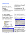
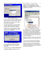
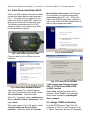
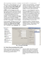
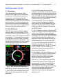
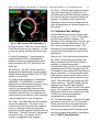
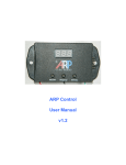
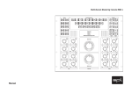
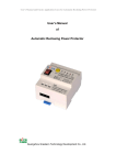
ARPrv Control v1.0
Software User Manual
doc-v1.0
Terms -- Conditions & Contact Information
This manual is copyrighted © by ARPC L.L.C. 2013-2014. All rights are reserved. This manual may only be reproduced
with permission of ARPC L.L.C.. This manual is furnished for informational use only and is subject to change without
notice. This manual does not imply any commitment on the part of ARPC LLC or its business partners. ARPC L.L.C. and
its business partners assume no responsibility or liability for any error or inaccuracies that may appear in this manual.
By use of this document for installation and operation of the ARP Control, the user is agreeing to the ARPC L.L.C. terms
and conditions found in document ARPC LLC License Agreement.pdf. Also, the end user needs to understand Section
1.6 of the User Manual; the end user has been informed that the ARP Control can be turned off at any time, thereby
removing the ARP Control function and reverting to the operation of the refrigerator to its previous state. Power surges
can turn off the ARP Control just the same as any equipment in an RV.
The document "ARPC LLC License Agreement.pdf" can be downloaded at web address
http://www.ARPrv.com
or, please send any request to e-mail address below, ARPC L.L.C. will supply information in a timely manner:
[email protected]
CONTENTS
INTRODUCTION ....................................................................................................................... 1
1.1 Acronyms and Abbreviations ....................................................................................... 1
1.2 ARP Software .............................................................................................................. 1
INSTALLATION ........................................................................................................................ 1
2.1 Software Installation .................................................................................................... 1
2.2 Cable Driver Installation W-XP .................................................................................... 3
2.3 Assign COM Port Number ........................................................................................... 3
2.4 Cable Driver Installation W-7 & W-8 ............................................................................ 4
Software User Guide ............................................................................................................... 5
3.1 Overview ..................................................................................................................... 5
3.2 File Structure ............................................................................................................... 5
3.3 Software User Settings................................................................................................ 6
3.4 TXT File....................................................................................................................... 7
Computer Settings .................................................................................................................. 8
Excel 2003 & 2007.................................................................................................................... 8
CONCLUSION .......................................................................................................................... 9
ARPrv Control Software User Manual v1.0 02/16/2014 © 2013-2014 ARPC L.L.C. All rights reserved.
1
INTRODUCTION
1.1 Acronyms and Abbreviations
ARP: ARP Control = ARPrv Control
RTD: ARP Control temperature sensor;
Resistance temperature detector is the type
of sensor used.
1.2 ARP Software
The ARP data collection software is used for
documentation of the cooling unit
characteristics for a particular make and
model of refrigerator. In addition, the ARP
data collection software helps to diagnose
and solve problems associated with RV
refrigerator cooling units.
It is assumed that the installer is familiar with
their computer operating system. The
following steps and figures are from a W-XP
operating system. It is recommended that an
installation be preformed only after a fresh
boot of the computer.
INSTALLATION
2.1 Software Installation
Use Windows Explorer to access the files
within the downloaded ARP_v2.x folder.
Please note that a directory and folder are
synonyms. Referencing Fig. 1, within the
ARP_v2.x folder reside a number of files and
folders you will use for the installation
process. Read and follow all on screen
instructions for proper installation.
Fig.1 Contents of Installation Folder
1. Double Click 'setup.exe'.
Fig. 2 ARPC L.L.C. Agreement
2. In order to install the program, select the 'I
agree…' radio button. By selecting the 'I
agree…' radio button, the 'Next>>' button will
be enabled, select 'Next>>' to proceed with
the install.
3. At the next screen select 'OK' if you have
closed all of your open programs.
Fig. 3 Install Directory and Begin
4. When Fig. 3 screen is reached, you may
install in the default directory, in this case
skip to step 6. Or, select 'Change Directory'
at the lower right of the window to install the
program in a location which you choose.
5. In the 'Path:' text box, for example, create
the new destination directory by typing:
C:\ARP_v2.x, where x is your version of the
ARP software.
ARPrv Control Software User Manual v1.0 02/16/2014 © 2013-2014 ARPC L.L.C. All rights reserved.
2
program start icon and drag out to the
desktop. Select 'Copy Here' or 'Create
Shortcut'. This will make it easy to start the
program when needed.
Fig. 4 Install Location
One may also use the Drives and Directories
options to locate an existing install location.
Select 'OK' when finished. Select 'Yes' to
create any new directories.
6. Once completing all of the above steps,
click the square button with an icon of a
computer within to begin the installation.
7. Next screen, unless you want to make
changes, it is recommended to accept the
defaults. Select 'Continue'.
Fig. 6 – Drop Folders on C-Drive
10. There are two folders that are located in
the install folder Fig. 1 that must be placed
on the C-drive. These folders contain the
Excel temples and provide the destination for
the TXT file produced by the ARP software
for a data collection session. See section 3.2
for more information.
Drag the two folders circled in Fig. 6 from the
installation folder Fig. 1 to C:\ as seen in Fig.
6.
Fig. 5 Successful Install
8. Once the program has been installed
successfully, Fig. 5 screen will appear.
Select 'OK'.
9. At this point go to: Start > All Programs
> ARP_v2.x folder > Right Click on the
You may want to open the Excel template
files in your version of Excel and customize
them for your use. Do not change the file
name or the extension (.xlt or .xltx) as this is
required for the ARP data collection program
to open these templates.
ARPrv Control Software User Manual v1.0 02/16/2014 © 2013-2014 ARPC L.L.C. All rights reserved.
3
2.2 Cable Driver Installation W-XP
Once your APR hardware has been installed,
connect the data collection cable as seen in
Fig. 7. The green wire is positioned to the
switch side (bottom) of the ARP control, the
black wire is on the LED display side (top).
The following instructions are for W-XP
operating system, your screens may differ,
but the procedure is similar.
Fig. 7 ARP Data Collection Cable
this location in the search', then ‘Browse’
for the location you stored the previously
downloaded folder ARP_v2.x. Within this
folder is the FTDI-Drivers folder, continue to
point to the CDM v2.08.28 Certified folder as
seen in the example path below:
Fig. 9 Point to Driver
Plug the cable in to the USB port on your
computer.
Fig. 10 Choose Driver Location
Fig. 8 Found New Hardware Wizard
The screen seen in Fig. 8 should appear.
There are 3 selections on this screen, select
‘No, not this time’. Then click ‘Next’.
When Fig. 9 appears, select ‘Install from a
list or specific location (Advanced)’, then
select ‘Next’.
The screen seen in Fig.10 will appear, select
‘Search for the best driver in these
locations’. Select the check box ‘Include
C:\Documents and Settings\ Desktop\
ARP_v2.1\FTDI-Drivers\CDM 2\CDM
v2.08.28 Certified
Select ‘Next’ and the first driver will be
installed. Select ‘Finish’, then a second
driver will be installed by repeating the
above example.
2.3 Assign COM Port Number
From the START menu, Right Click ‘My
Computer’ in W-XP, or just ‘Computer’ in W7. Select ‘Properties’ and then the Hardware
ARPrv Control Software User Manual v1.0 02/16/2014 © 2013-2014 ARPC L.L.C. All rights reserved.
tab in W-XP, or ‘Device Manager’ in W-7. Fig.
11 shows in the Device Manager tree on the
left, under the heading Ports (COM & LPT),
the ARP data collection for this particular
install was assigned ‘USB Serial Port
(COM4)'. See the Software User Guide
below, step 5, where COM4 would mean that
the value placed in the input text box for the
ARP Data Collection user interface would be
4. Many different types of devices are
connected using the COM ports to a
computer. The only ports that the ARP data
collection can use are COM1 through COM8.
You may need to shuffle the COM port
numbers on your computer to accommodate
the COM 1-8 requirement. On the computer
for this example, COM4 was not in use. The
assigned ports may be determined by Right
Clicking on the ‘USB Serial Port (COM4)’,
selecting ‘Properties’, the center window in
Fig. 11 will appear, select ‘Advanced’, the
window to the right will appear. Use the pop
down list at the top of this window to check
and reset your COM port setting. It is up to
the operator to determine the best method to
establish connection with the ARP Data
Collection. It may be that a device such a
GPS can accept any COM port. In this case,
reassign the GPS COM port, reboot your
computer, and then assign the desired COM
port number to the ARP data collection port.
The ‘(in use)’ ports can be reassigned by
changing the number of the port and then
rebooting. It is advised to plug and then
unplug your USB devices that use the COM
ports in order to make a list of which devices
use which COM port, only then start
reassigning numbers. Remember that the
computer needs to be rebooted to make the
COM port changes. This procedure is only
need once upon initial install of your
hardware.
Fig. 11 Change Port Number
2.4 Cable Driver Installation W-7 & W-8
Please use this section with section 2.2 & 2.3,
older versions of W-7 software install the
same as W-XP. The later versions will use
the following generalized method:
4
Insert your cable, when the driver install
window comes up; select to include the
internet for the search. The correct driver
should be automatically loaded from the
internet through the Windows driver install
routine.
ARPrv Control Software User Manual v1.0 02/16/2014 © 2013-2014 ARPC L.L.C. All rights reserved.
5
Software User Guide
3.1 Overview
The software interface features digital
readouts of the present boiler temperature,
the set-point, and the absolute maximum
temperature recorded during the data
collection session. In addition, there is an
analog meter that displays all of the aforesaid
data in real time. The units of measure can
be set to either Celsius or Fahrenheit, plus
there is a clock that counts the approximate
duration of the data collection session.
3.2 File Structure
The ARP data collection software always
stores the data in a Tab Delimited TXT file.
The data can also be stored in MS-Excel if a
compatible version of this software resides on
the computer. It is assumed that the reader
is familiar their version of Excel or another
spreadsheet program like OpenOffice. If the
operator does not want to use Excel, simply
close Excel after the ARP data collection
program has fully opened.
2. The PAUSE button will halt the data
collection. If one needs to stop data collection
and then restart the recording, simply click on
the START button to resume data collection.
Always PAUSE the data collection session to
click in, or work on Excel. Otherwise the data
collection may stop unexpectedly.
3. PAUSE Indicator. When the PAUSE
button is clicked, this indicator will be the
same color as the PAUSE button. When the
program has been started with the START
button, the color will change to the same as
the START button.
4. Port Connection Indicator. When the ARP
control is turned on, and in the data collection
mode, if your COM port is not configured
correctly, this indicator will be illuminated red
and display "No Port Found", otherwise when
a port is connected and the software can
read from the port, this display will be green.
Please see section 2.2 if port errors exist.
5. If you need to change the number of your
COM port to match the cable, enter its
number into this text box. In Fig. 12, the port
is set to COM5. Once the COM port is
connected properly proceeded to the next
step to store the change.
6. Save Button. If the units of measure (°F or
°C), the COM Port number, or other savable
settings have been changed, press this
button so that the next time the program
starts, the changes will take effect.
Refer to Fig. 13 for the following discussion:
Fig. 12 ARP Control GUI Displaying °C
Refer to Fig. 12 for the following discussion:
1. The START button will begin reading the
ARP control boiler temperature and other
parameters.
7. Select the preferred units of temperature
measurement. In order to save the setting,
use the save button step 6. Note, when
using MS Excel, upon saving and closing the
data collection program, the subsequent
opening of the program will open the
appropriate Excel template and display the
preferred units.
ARPrv Control Software User Manual v1.0 02/16/2014 © 2013-2014 ARPC L.L.C. All rights reserved.
6
13. Close. Close the data collection session
using the close button. If using Excel, It is
recommended to PAUSE the data collection,
then saving the Excel file before closing the
program. In addition, at this location the
'Maximize' button is located; please see the
User Settings below for more information on
this subject.
3.3 Software User Settings
Fig. 13 ARP Control GUI Displaying °C
8. Excel Version. Select the correct version
of MS-Excel used on your computer. In order
to save the setting, use the save button step
6.
9. Boiler Temperature. The temperature
measured by the RTD is displayed both
digitally and using the analog display while
being recorded in the TXT file and/or in an
Excel file.
10. Set-Point. The ARP control set-point is
displayed both digitally and using the analog
display while being recorded in the TXT files
and/or in an Excel file.
11. Boiler Absolute Maximum Temperature
(ABS MAX). The ABS MAX is recorded
digitally for the data collection session. This is
a handy feature for setting up the ARP
control or just knowing the situations that
could results in higher boiler temperatures.
In addition, after an Auto Tune session this
value should be recorded for future reference
to aid in diagnostics of your refrigerator.
12. Clock. The data collection clock actually
counts the data points. The clock is not a
real time clock and is provided as a method
for one to observe events and record the
timing for use with graphical methods such as
Excel plots. The clock counts by two second
intervals. 2 hours, 12 minutes, and 18
seconds is displayed in this example.
Use the Maximize button at the upper right
corner as seen in Fig. 13, box 13 to expand
the ARP data collection interface. The
following custom settings need to be set, and
then saved using the button seen in Fig. 12
box 6 once your settings are made. The
following are recommendations; ultimately
the user can choose their own settings and
preferences.
Refer to Fig. 14 for the following discussion:
14. Offset. Offset gives the operator the
ability to calibrate the ARP data collection
reading to a trusted temperature
measurement that is known to be at the same
temperature as the boiler temperature RTD.
This setting is saved when the Save Button in
step 6 is pressed. It is recommended upon
initial setup to make sure this value is zero if
the operator does not want to add their own
offset. The offset does not change the ARP
control functions. The ARP display offset is
separate from the ARP data collection
software offset. It is best if both of the offsets
agree. For consistency, it is recommended
keeping this value at zero unless one is able
to make very accurate temperature
measurements for calibration.
15. File Path and Name. This is the file path
and name of the file for the TXT file saved.
Please note that the correct path has been
inserted into the text box in this example.
One may copy and paste the following path
into this box upon initial setup for the default
path: C:\ARPC_DataCollection\
ARPrv Control Software User Manual v1.0 02/16/2014 © 2013-2014 ARPC L.L.C. All rights reserved.
7
Fig. 14 User Settings
16. Meaningful File Name Prefix. For
example, user may define the type of
refrigerator model in the path described in
step 15. Box 16 shows an example of data
collection for a Norcold N1200 series
refrigerator, more on this subject below in
section 3.4.
17. Analog Scale. The upper and lower
limits of the analog meter must be set here
before initial use. This setting gives the user
of the ARP control the ability to measure any
surface temperature within the range of 0250°C (32-482°F), for any purpose which is
not submerged in liquid. Set the desired
units of measure as described in step 7
above and then set the desired range of
measurement with the Analog Scale Min and
Max.
18. Data Clock Rate. The ARP control data
collection software uses your computer
internal clock for data collection timing. This
setting is for troubleshooting and advanced
use only.
19. Input Measurement. This display shows
the resistance of the RTD being measured
by the ARP control. The ARP control can
measure any resistance type temperature
probe. Please contact ARPC L.L.C. if
modifications to the control and computer
software may be adapted for your application.
In addition, one should check these values if
trouble shooting of the data collection is
necessary.
3.4 TXT File
As per instructions found above in section
2.1 step 10, the directory/folder that was
placed at location C:\ARPC_Data Collection
will contain text files (.TXT) for the data
collection sessions. The automatically saved
files can be used at a later date to be
imported or copied and pasted into a
spreadsheet program. This feature gives the
operator the ability to process the collected
data with just about any spreadsheet
program. The name of the automatically
saved files will be saved in the following
format:
N1200_20130810121419.txt
The beginning of the stored file name,
identified above in bold (N1200_) was set by
the user in step 16. Any prefix to the file
name may be included. For example,
'Coffee' may be used for measuring the
temperature of a coffee maker process if so
desired.
The colored portions of the file name are
follows:
Year = 2013; Month = August (08); Day =
10th. The time is represented in 24 hour
format read from your computer clock. Hour
= 12; Minute = 14; Second = 19
ARPrv Control Software User Manual v1.0 02/16/2014 © 2013-2014 ARPC L.L.C. All rights reserved.
8
Computer Settings
In order to collect data, the computer needs
to be setup so that the low power modes do
not stop the data collection process. Due to
the fact that each computer manufacture
manages the low power modes differently,
we will give a general description of how to
keep the computer processor and hard drive
running while the screen turns off for low
power mode.
1. Within the Control Panel, Power
Settings is found.
2. The Power Settings need to be set in
the following manner:
a)
Screen shuts off
b)
Hard drive remains running
c)
Never hibernate (XP)
d)
Never put computer to sleep
when plugged in (W-7 on)
Excel 2003 & 2007
A word of caution concerning Excel and the
ARP control data collection software:
Whenever accessing Excel, including
minimizing and maximizing the program,
always make sure that the ARP data
collection is PAUSED, the user may START
the ARP data collection again after any
changes are made to Excel. If the ARP data
collection is not PAUSED when clicking in
Excel, often the data collection will stop, and
it will not resume until both Excel and the
ARP data collection program are closed and
then reopened.
Refer to Fig. 15 for the following discussion:
When MS-Excel is used for data collection, a
recording of a particular refrigeration unit
may be archived in a data base for future
comparison. The boiler curve reveals many
parameters of the refrigeration system under
consideration. When these parameters are
used properly, they reveal the present
condition of your refrigerator. If a technician
has been trained properly, it takes but a
moment to determine where potential
problems may exist. Please see the
Troubleshooting Guide for more details on
this subject.
During a data collection session, an
operator/technician can identify events by
taking notes with reference to the Clock (step
12). From experience, Excel 2003 will plot
the curve in real time giving the operator an
alternate method for graphical representation
of the boiler temperature verses the set-point
value. There are a lot of factors, such as
graphics card memory and speed, system
memory and processor speed, which control
a particular computers ability to view Excel
data in real time. There are methods to
optimize a computer for data collection, but
this is beyond the scope of this document. It
is recommended running only the APR data
collection program during a data collection
session, after the data collection session has
been PAUSED, save any files, then open
any ancillary programs which the operator
desires to use.
20. Boiler Curve. The blue curve is the
boiler curve for a Dometic RM3663
refrigerator.
21. Set-Point Curve. The set-point is a
dynamic variable, depending on which mode
of operation your APR control has been set
to. Please see ARP User Manual section 3.4
& 3.5, C-H or C-L variable for further
information.
The set-point curve shows the operator the
present state of the set-point at which the
ARP control will turn off your refrigeration
heat source.
Excel 2007 may take too much of your
computers processor power. The supplied
ARPrv Control Software User Manual v1.0 02/16/2014 © 2013-2014 ARPC L.L.C. All rights reserved.
Excel 2007 template is set to not calculate
the data curves. The operator may change
this in the template if so desired; otherwise
the following method is use for the
calculation of the data curve:
After data collection is completed, PAUSE
the data collection program. Maximize Excel
2007 and then perform the following steps:
22. Select the Formulas tab, then either use
the 'F9' function key on your keyboard, or
simply select the 'Calculate Now' option.
23. Select Calculations Options. If the
operator desires, the method of calculation
may be changed with the 'Automatic' or
'Manual' selections.
9
'Automatic', the data curve will be calculated
automatically.
Note: The telltale sign by which one can
determine if a computer can or can not view
Excel data in real time is the Clock (step 12).
If your Clock is very inaccurate, very slow,
when compared to a real time clock, chances
are your computer is working too hard to
calculate the data curves seen in Fig. 15.
Your computer can not process the data
being sent to it by the ARP control, process
this data, and calculate a graph curve at the
same time. It is the operator's responsibility
to know the proper methods by which to
manage their own computer in order to
obtain accurate data collection results.
If your computer has the ability to view the
Excel data curve in real time, select
Fig. 15 Excel 2007
CONCLUSION
The ARPrv Control that has the collect data option makes it easy to test RV refrigerators.
Normal boiler temperatures may be recorded and compared to a refrigerator that is not
functioning correctly. Please use this document in conjunction with the Troubleshooting Guide
for fast testing of cooling units.