1
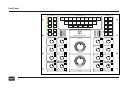
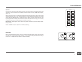
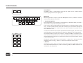
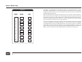
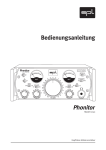
Multichannel Mastering Console MMC 2
Sources
Stereo
Input A
Stereo
Input B
Stereo
Return A
Stereo
Return B
M-CH.
Input A
M-CH.
Input B
M-CH.
Return A
M-CH.
Return B
M-CH.
Return C
M-CH.
Return D
Dim
Dim 1
-10 dB
Stereo
B
Dim 2
-20 dB
M-CH.
A
Dim 3
-30 dB
M-CH.
B
Mute
MMC 2
Insert
On
Return
On
Multichannel Mastering Console
Insert
Return
C
R
LS
RS
LFE
L t/o
R t/o
Solo
Solo
Solo
Solo
Solo
Solo
Solo
Solo
Stereo
Operation
Mono
LS/RS
2
-1 0 1
2
-2
ø Rev
3
-3
4
-4
5
-5
6
-6
7
-7
8
-8
9
-9
-10 dB 10
Trim
On
Trim
R
Trim
C
On
On
Trim
On
Trim
-1 0 1
2
-2
ø Rev
3
-3
4
-4
5
-5
6
-6
7
-7
8
-8
9
-9
-10 dB 10
Lt/o
Trim
Rt/o
Input
LFE
Trim
Monitor Level
On
Trim
On
Trim
RS
On
On
8
-1 0 1
2
-2
Fader
3
-3
On
4
-4
5
-5
6
-6
7
-7
8
-8
9
-9
-10 dB 10
Lt/o
Model 2486
Trim
-1 0 1
2
-2
Fader
3
-3
On
4
-4
5
-5
6
-6
7
-7
8
-8
9
-9
-10 dB 10
7
-1 0 1
2
-2
ø Rev
3
-3
4
-4
5
-5
6
-6
7
-7
8
-8
9
-9
-10 dB 10
On
On
6
LS
8
7
Trim
-1 0 1
2
-2
Fader
3
-3
On
4
-4
5
-5
6
-6
7
-7
8
-8
9
-9
-10 dB 10
On
On
-1 0 1
2
-2
Fader
3
-3
On
4
-4
5
-5
6
-6
7
-7
8
-8
9
-9
-10 dB 10
5
RS
Trim
R
4
C
-1 0 1
2
-2
ø Rev
3
-3
4
-4
5
-5
6
-6
7
-7
8
-8
9
-9
-10 dB 10
On
On
-1 0 1
2
-2
Fader
3
-3
On
4
-4
5
-5
6
-6
7
-7
8
-8
9
-9
-10 dB 10
6
Trim
Trim
L
-1 0 1
2
-2
Fader
3
-3
On
4
-4
5
-5
6
-6
7
-7
8
-8
9
-9
-10 dB 10
3
LFE
-1 0 1
2
-2
ø Rev
3
-3
4
-4
5
-5
6
-6
7
-7
8
-8
9
-9
-10 dB 10
2
-1 0 1
2
-2
Fader
3
-3
On
4
-4
5
-5
6
-6
7
-7
8
-8
9
-9
-10 dB 10
-1 0 1
2
-2
ø Rev
3
-3
4
-4
5
-5
6
-6
7
-7
8
-8
9
-9
-10 dB 10
5
LS
Mono
Lt/o/Rt/o
Master Fader
4
-1 0 1
2
-2
ø Rev
3
-3
4
-4
5
-5
6
-6
7
-7
8
-8
9
-9
-10 dB 10
M-CH.
Operation
LFE to
L/C/R
1
-1 0 1
2
-2
ø Rev
3
-3
4
-4
5
-5
6
-6
7
-7
8
-8
9
-9
-10 dB 10
3
Manual
Stereo
A
L
Mono
L/R
1
L
Monitors
Speaker Management
Solo to
Center
Trim
-1 0 1
2
-2
Fader
3
-3
On
4
-4
5
-5
6
-6
7
-7
8
-8
9
-9
-10 dB 10
On
Rt/o
Output
Trim
On
Multichannel Mastering Console MMC 2, Model 2486
Manual
Manual Version 1, 10/2005
R & D: Wolfgang Neumann
The information in this document has been carefully verified and is assumed to be
correct. However Sound Performance Lab (SPL) reserves the right to modify the
product described in this manual at any time. Changes without notice. This document
is the property of SPL and may not be copied or reproduced in any manner, in part or
full without the authorization of SPL.
Limitations of Liability:
In no event will SPL be liable for any damages, including loss of data, lost profits,
cost of cover or other special, incidental, consequential or indirect damages arising
from the use of the unit, however caused and on any theory of liability. This limitation will apply even if SPL or an authorized dealer has been adviced of the possibility
of such damage.
Sound Performance Lab
SPL electronics GmbH
P.O. Box 12 27, D- 41368 Niederkruechten, Germany
Phone +49 2163 983 40, Fax +49 2163 983 420
Email: [email protected], Internet: www.soundperformancelab.com
© 2005 SPL electronics GmbH
All rights reserved. Technical specifications and appearance are subject to change
without notice.
2
Contents
Fade In ................................................................................................
4
Monitor Level ......................................................................................
9
Signal Flow ..........................................................................................
5
Option: MasterBay .............................................................................
10
Front Panel ..........................................................................................
6
Rear Panel, XLR Wiring, Metering Out ..................................................
11
Control Elements ................................................................................
7
Measurements .................................................................................... 12-18
Sources, Input Trims ...........................................................................
7
Specifications, Power Supply ..............................................................
19
Insert/Return, Speaker Management, Monitors ..................................
8
Warranty .............................................................................................
20
Installation/Security Advices
Before you operate the unit, first check carefully whether the local voltage
setting corresponds to the setting on the external transformer!
• Do not open the case. You may risk severe electric shock and may damage
your equipment.
Before switching on external transformer and MMC 2, the MMC 2 must be
connected to the external transformer with the supplied multicore lead. Pay
attention to a secure connection.
• Leave repairs and maintenance to a qualified service technician. Should any
objects fall inside the case, unplug the power supply and contact a qualified technician.
The MMC 2 and the external transformer should be situated away from heat
sources and direct sunlight. MMc 2 and transformer need sufficient air circulation. Avoid installation in environments exposed to vibrations, dust, heat,
cold, moisture or electrical and magnetic fields.
• To avoid electric shock or fire hazards do not expose the unit to rain or
dampness.
Do not install the unit in proximity to power amplifiers or digital processors.
You may consider placing it near other analog gear. Such placement can
prevent interference from Word Clock, MIDI, etc.
• In case of lightning unplug the power supply.
• Never force a switch or knob.
• Use a lint-free cloth for cleaning. Avoid any cleaning agents as they may
damage the finish, use an acid-free cleaning oil instead.
• Support the back of the unit when it is being mounted.
3
Fade In
Master Fader
Moreover additional prerequisites speak for the employment of high-performance analog technology:
The number of necessary AD/DA conversions should be reduced to a minimum.
With the MMC 2, digital sources can be connected to a digital router, which
outputs the selected source through the preferred DA converter. This ensures
that the sound quality remains comparable and is not affected by converter
differences.
High quality analog outboard processing consistently proves itself superior
to digital processing. The analog concept allows for problem-free integration
of such analog processors.
The MMC 2 multichannel mastering console completes the range of SPL 120 V
mastering consoles. Housed in a 19”/11U rack mount chassis the MMC 2
features the same unique 120 volts rails like the MMC 1 and DMC dual-channel
mastering console to achieve the optimum audio performance.
The purpose of the development was the creation of mastering consoles
that would be superior in audio quality to all known and foreseeable audio
formats, whether analog or digital. Such consoles would provide both for
an unaltered reproduction of the sonic quality of high resolution playback
formats like SACD and in the process, remain a safe capital investment for
many years.
The MMC 2 is conceived as the center of a mastering environment to provide
speaker management, sources and returns connectivity, input and output
trimming, pure analog multichannel master fader and monitor level setting.
As an option, the MMC 2 can be supplemented with the SPL MasterBay to
provide an automated 8 x 8 channel insert routing of external processors.
Digital audio formats have undergone continuous development and change
and will continue to do so. With the degree of incompatibility created by the
“format war” between PCM and DSD, the need for a technology that is superior in dynamic range, headroom and sound quality to either or any other such
format is obvious – and the only solution is discrete analog technology in its
most advanced implementation.
4
Monitors and power amplifiers are almost exclusively analog in design. Yet
another converter at this point in the chain only degrades monitoring signal
paths. Furthermore, DSD signals cannot be monitored on a digital monitoring
that operates in PCM.
Technology
SPL’s new SUPRA operation amplifiers are used throughout the MMC 2’s
design. They perform at an industry benchmark of 120 volts and their development alone took four years. The SPL SUPRA op amp achieves a signal-tonoise ratio of 116 dB with a headroom of 34 dB. The dynamic range amounts
to 150 dB with a frequency bandwidth of 200 kHz.
With such specifications, the MMC 2 rides comfortably beyond the requirements of either the current maximum 24 bit/192kHz PCM or 1 bit/256 fs
DSD formats, while a digital technology in which the MMC 2 could become a
“bottle neck” is not foreseeable.
Signal Flow
8 channel bus
insert send/
return
(bal. drivers
and receivers)
2x
STEREO
INPUTS
(balanced)
2x
M-CH.
INPUTS
4x STEREO
RECORDING
OUTPUTS
PHASE
REVERSE
switch
(passive)
Balanced
input
receivers
TRIM ON
switch/
TRIM control
+/- 10 dB
INSERT
BYPASS
switch
(relay)
TRIM ON
switch/
TRIM control
+/- 10 dB
MASTER
FADER ON/
MASTER
FADER
(bal. drivers)
2x M-CH.
RECORDING
OUTPUTS
(balanced)
(bal. drivers)
2x
STEREO
RETURNS
2x STEREO
MONITOR
OUTPUTS
(bal. receiver)
4x
M-CH.
RETURNS
(bal. receiver)
Monitoring/Speaker Management
ON, SOLO, MONO, SOLO TO CENTER,
L/C/R TO LFE, STEREO-/M-CH. OPERATION
MONITOR SELECTION, DIM, MUTE
(bal. drivers)
2x M-CH.
MONITOR
OUTPUTS
(bal. drivers)
5
Front Panel
Sources
Stereo
Input A
Stereo
Input B
Stereo
Return A
Stereo
Return B
M-CH.
Input A
M-CH.
Input B
M-CH.
Return A
M-CH.
Return B
M-CH.
Return C
M-CH.
Return D
Dim
Dim 1
-10 dB
Stereo
B
Dim 2
-20 dB
M-CH.
A
Dim 3
-30 dB
M-CH.
B
Mute
MMC 2
Insert
On
Return
On
Multichannel Mastering Console
Insert
Return
C
R
LS
RS
LFE
L t/o
R t/o
Solo
Solo
Solo
Solo
Solo
Solo
Solo
Solo
Stereo
Operation
Mono
LS/RS
2
-1 0 1
2
-2
ø Rev
3
-3
4
-4
5
-5
6
-6
7
-7
8
-8
9
-9
-10 dB 10
Trim
On
Trim
R
Trim
C
On
On
Trim
On
Trim
-1 0 1
2
-2
ø Rev
3
-3
4
-4
5
-5
6
-6
7
-7
8
-8
9
-9
-10 dB 10
Lt/o
Trim
Rt/o
Input
LFE
Trim
Monitor Level
On
Trim
On
Trim
RS
On
On
8
-1 0 1
2
-2
Fader
3
-3
On
4
-4
5
-5
6
-6
7
-7
8
-8
9
-9
-10 dB 10
Lt/o
Model 2486
Trim
-1 0 1
2
-2
Fader
3
-3
On
4
-4
5
-5
6
-6
7
-7
8
-8
9
-9
-10 dB 10
7
-1 0 1
2
-2
ø Rev
3
-3
4
-4
5
-5
6
-6
7
-7
8
-8
9
-9
-10 dB 10
On
On
6
LS
8
7
Trim
-1 0 1
2
-2
Fader
3
-3
On
4
-4
5
-5
6
-6
7
-7
8
-8
9
-9
-10 dB 10
On
On
-1 0 1
2
-2
Fader
3
-3
On
4
-4
5
-5
6
-6
7
-7
8
-8
9
-9
-10 dB 10
5
RS
Trim
R
4
C
-1 0 1
2
-2
ø Rev
3
-3
4
-4
5
-5
6
-6
7
-7
8
-8
9
-9
-10 dB 10
On
On
-1 0 1
2
-2
Fader
3
-3
On
4
-4
5
-5
6
-6
7
-7
8
-8
9
-9
-10 dB 10
6
Trim
Trim
L
-1 0 1
2
-2
Fader
3
-3
On
4
-4
5
-5
6
-6
7
-7
8
-8
9
-9
-10 dB 10
3
LFE
-1 0 1
2
-2
ø Rev
3
-3
4
-4
5
-5
6
-6
7
-7
8
-8
9
-9
-10 dB 10
2
-1 0 1
2
-2
Fader
3
-3
On
4
-4
5
-5
6
-6
7
-7
8
-8
9
-9
-10 dB 10
-1 0 1
2
-2
ø Rev
3
-3
4
-4
5
-5
6
-6
7
-7
8
-8
9
-9
-10 dB 10
5
LS
Mono
Lt/o/Rt/o
Master Fader
4
-1 0 1
2
-2
ø Rev
3
-3
4
-4
5
-5
6
-6
7
-7
8
-8
9
-9
-10 dB 10
M-CH.
Operation
LFE to
L/C/R
1
-1 0 1
2
-2
ø Rev
3
-3
4
-4
5
-5
6
-6
7
-7
8
-8
9
-9
-10 dB 10
3
6
Stereo
A
L
Mono
L/R
1
L
Monitors
Speaker Management
Solo to
Center
Trim
-1 0 1
2
-2
Fader
3
-3
On
4
-4
5
-5
6
-6
7
-7
8
-8
9
-9
-10 dB 10
On
Rt/o
Output
Trim
On
Control Elements
Sources
Sources
The Sources section provides selection options for several stereo and multichannel input
and return sources. The returns are ideally suited to select recorders, DAW, audio players,
and so on.
All Input buttons allow for switching between the input monitoring mode and the output
monitoring mode. Press once, the input button is permanently illuminated. The output
signal after the Master Fader is monitored. Press again, the Input button flashes. The
input signal after the input Phase Reverse switch is monitored. This way, you can easily
compare what comes in and what goes out of the console.
IMPORTANT: Selecting the return monitoring mode overrules input and output monitoring modes.
NOTE: All MMC 2 buttons allow for individual labeling.
Input Trims
An input selected in the Source section is routed to the Input Trims section. This section
provides On and Phase Reverse switches, a high-grade ALPS potentiometer with 41
steps and +/-10dB gain range allows for input trimming.
Stereo
Input A
Stereo
Input B
Stereo
Return A
Stereo
Return B
M-CH.
Input A
M-CH.
Input B
M-CH.
Return A
M-CH.
Return B
M-CH.
Return C
M-CH.
Return D
7
8
-1 0 1
2
-2
ø Rev
3
-3
4
-4
5
-5
6
-6
7
-7
8
-8
9
-9
-10 dB 10
Lt/o
Trim
-1 0 1
2
-2
ø Rev
3
-3
4
-4
5
-5
6
-6
7
-7
8
-8
9
-9
-10 dB 10
On
Rt/o
Trim
On
Input
7
Control Elements
Insert/Return
Insert
On
Return
On
Insert
Return
The MMC 2 offers an Insert/Return point after the Input Trims to include external
processing equipment into the signal path.
Monitoring
Speaker Management
Solo to
Center
L
C
R
LS
RS
LFE
L t/o
R t/o
Solo
Solo
Solo
Solo
Solo
Solo
Solo
Solo
Mono
L/R
Stereo
Operation
Mono
LS/RS
M-CH.
Operation
Mono
Lt/o/Rt/o
LFE to
L/C/R
Monitoring functions comprise a Speaker Management section, a Monitors selection
section and the Monitor Level fader.
1. Speaker Management
Each loudspeaker can be activated or deactivated by a dedicated switch, and each is
labeled with its respective loudspeaker position.
A Solo switch is placed underneath each speaker switch. To alleviate channel comparisons, a Solo-to-Center function allows for monitoring of each channel through the
center speaker. The Solo-to-Center function can only be activated if a speaker is previously switched to solo.
If a surround sound mix does include separate LFE subwoofer signals, the LFE-to-L/C/R
switch distributes an LFE signal (factory standard -10 dB level) to the L/C/R channels.
Monitors
8
Two Operation Mode buttons are provided to change the MMC 2 configuration from
stereo to multi-channel operation. For improved operational safety and to switch off all
monitoring functions other than L/R, the Stereo button must be pressed before starting
a stereo mastering job.
Stereo
A
Dim 1
-10 dB
Stereo
B
Dim 2
-20 dB
M-CH.
A
Dim 3
-30 dB
2. Monitors
M-CH.
B
Mute
The Monitors section allows for selection of two stereo and two multichannel speaker
sets. Three different Dim levels (-10 dB, -20 dB and -30 dB) and a Mute switch can be
activated for the selected set.
The Monitor section offers three mono functions: 1. Mono L/R, 2. Mono LS/RS (not
available in stereo mode), 3. Mono L t/o / R t/0 (not available in stereo mode).
Control Elements
Monitor Level
The Monitor Level is controlled with a custom-made eight-tiered potentiometer. The
MMC 2 does not employ DACs, step ladders or VCAs for this function, and the specifications of this potentiometer are substantially better than either of these other options
ever could be – the maximum tolerance is ‹ 0,5 dB over the entire control range. The
control range reaches from -∞ dB to +4 dB.
Monitor Level
Master Fader
Master Fader
This fader features the same potentiometer of the Monitor Level for dynamic mastering
purposes and fine tuning the overall level from +10 dB to -80 dB.
Each output channel must be activated by the Fader On switch in the respective Output
Trim section to be controlled by the master fader.
With this control’s extremely fine level settings, the engineer can attain every ounce
of recording headroom. The result, thanks to these controls of infinite resolution, is an
unparalleled excellence in dynamic mastering.
Output Trims
The Output Trims are based on the same high-quality ALPS potentiometers like in the
Input section and the gain range also covers +/-10dB. Each output can be activated or
deactivated separately with the ON switch, the Fader On switch routes each output to
the Master Fader.
7
8
-1 0 1
2
-2
Fader
3
-3
On
4
-4
5
-5
6
-6
7
-7
8
-8
9
-9
-10 dB 10
Lt/o
Trim
-1 0 1
2
-2
Fader
3
-3
On
4
-4
5
-5
6
-6
7
-7
8
-8
9
-9
-10 dB 10
On
Rt/o
Trim
On
Output
9
Option: Master Bay
The MMC 2 can optionally be complemented with an automated insert box called
MasterBay. The MasterBay consists of an 8U insert box and a remote control panel. Up
to eight 8-channel processors can be connected to the insert box, which is operated by
the MasterBay remote panel.
MasterBay
Sequence
Position
1
2
3
10
Processor
Selection
Store/
Recall
Processor
Store
1
1
Processor
Store
2
2
Processor
Store
3
3
4
Processor
4
New
5
Processor
Recall
5
1
6
Processor
Recall
6
2
7
Processor
Recall
7
3
8
Processor
8
Bypass
With the MasterBay the engineer can specify up to four routings, called sequences,
which can be stored and re-called. The remote panel provides a button for each of the
eight external processors. Depressing these in sequence switches among choices in
processor signal flow. Next to the buttons is a seven segment LED-display indicating
the current position of the processors in the sequence.
The mastering engineer can use this feature to compare between sequences in a varying
order or to compare the same type of processors—such as in the case of an equalizer
from Manufacturer A and one of Manufacturer B. Three memory banks are available
which allow an active signal flow sequence to be compared instantly at a push of a
button with three others (for a total of four). If the optional MasterBay is connected, the
MMC 2’s Insert On switch activates the MasterBay or switches it to hard-bypass.
R t/o
8
L t/o
7
RS
5
LS
5
LFE
4
C
3
K
U
A
C
A
N
H
M
A
E
A
R
D
P
J
C
B
F
S
A
A
A
K
A
D
A
P
A
L
V
N
A
L
W
T
A
F
A
S
X
A
B
A
M
Y
A
H
A
T
REC OUT
M-CH.
E
R
Z
A
J
CANADA
516-38
R4
L4
R3
L3
R2
L2
R1
K
U
A
C
A
N
H
M
A
E
A
R
D
P
J
C
B
F
S
A
A
A
K
A
D
A
P
A
L
V
N
A
L
W
T
A
F
A
S
X
A
B
A
M
Y
A
H
A
T
REC OUT
STEREO
EDAC
R
2
E
R
Z
A
J
CANADA
516-38
K
U
A
C
A
N
H
M
A
E
A
R
D
P
J
C
B
F
S
A
A
A
K
A
D
A
P
A
L
V
N
A
L
W
T
A
F
A
S
X
A
B
A
M
Y
A
H
A
T
E
R
Z
A
J
MONITOR B
R t/o
8
L t/o
7
RS
5
LS
5
LFE
4
C
3
R
2
M-CH.
L
1
EDAC
Stereo
CANADA
516-38
L1
K
U
A
C
A
N
H
M
A
E
A
R
D
P
J
C
B
F
S
A
A
A
K
A
D
A
P
A
L
V
N
A
L
W
T
A
F
A
S
X
A
B
A
M
Y
A
H
A
T
E
R
Z
A
J
MONITOR A
R t/o
8
L t/o
7
RS
5
LS
5
LFE
4
C
3
R
2
M-CH.
L
1
EDAC
R
CANADA
516-38
R
B
L
B
R
A
EDAC
EDAC
A
N
K
U
A
C
A
N
K
U
A
C
H
M
A
E
A
D
H
M
A
E
A
R
D
J
C
B
F
S
A
A
A
K
A
D
A
P
A
A
L
V
N
A
L
B
X
P
T
A
F
A
S
C
F
Y
A
B
A
M
J
L
W
A
H
A
T
D
P
S
A
A
A
K
V
N
A
L
A
P
W
T
A
F
A
R
X
A
B
A
M
A
S
Y
A
H
A
T
E
R
Z
A
J
E
R
Z
A
J
CANADA
516-38
CANADA
516-38
R
R4
L4
R3
L3
A
N
K
U
A
C
A
T
H
M
A
E
A
R
D
P
J
C
B
F
S
A
A
A
K
A
D
A
P
A
L
V
N
A
L
W
T
A
F
A
S
X
A
B
A
M
Y
A
H
A
J
E
R
Z
R t/o
8
L t/o
7
RS
5
LS
5
LFE
4
C
3
L2
R2
R
2
K
U
A
C
A
N
H
M
A
E
A
R
D
P
J
C
B
F
S
A
A
A
K
A
D
A
P
A
L
V
N
A
L
W
T
A
F
A
S
X
A
B
A
M
Y
A
H
A
T
RETURN
M-CH. B
M-CH.
L
1
R1
RETURN
STEREO
Stereo
L1
EDAC
STEREO RETURNS
CANADA
516-38
L
A
EDAC
L
E
R
Z
A
J
CANADA
516-38
L
R t/o
8
L t/o
7
RS
5
LS
5
LFE
4
C
3
R
2
K
U
A
C
A
N
H
M
A
E
A
R
D
P
J
C
B
F
S
A
A
A
K
A
D
A
P
A
L
V
N
A
L
W
T
A
F
A
S
X
A
B
A
M
Y
A
H
A
T
RETURN
M-CH. A
M-CH.
L
1
EDAC
VU OUTPUTS
E
R
Z
A
J
CANADA
516-38
Stereo
Stereo
K
U
A
C
A
N
H
M
A
E
A
R
D
P
J
C
B
F
S
A
A
A
K
A
D
A
P
A
L
V
N
A
L
W
T
A
F
A
S
X
A
B
A
M
Y
A
H
A
T
E
R
Z
A
J
INPUT
ST & M-CH B
R t/o
8
L t/o
7
RS
5
LS
5
LFE
4
C
3
R
2
M-CH.
L
1
R
L
EDAC
M-CH.
L
1
EDAC
CANADA
516-38
INSERT RETURN
M-CH. RETURN C
Stereo
K
U
A
C
A
N
H
M
A
E
A
R
D
P
J
C
B
F
S
A
A
A
K
A
D
A
P
A
L
V
N
A
L
W
T
A
F
A
S
X
A
B
A
M
Y
A
H
A
T
E
R
Z
A
J
INPUT
ST & M-CH A
R t/o
8
L t/o
7
RS
5
LS
5
LFE
4
C
3
R
2
M-CH.
L
1
R
L
EDAC
M-CH. RETURN D
CANADA
M-CH. METERING OUT
516-38
Stereo
Rear Panel/XLR Wiring/Metering Out
INSERT SEND
M-CH. RETURN B
PUSH
2
3
1
1
3
1 = Ground, 2 = hot (+), 3 = cold (-)
2
Pin Wiring XLR Inputs
1 = Ground, 2 = hot (+), 3 = cold (-)
Pin Wiring XLR Outputs
Please refer to the service documentation for
EDAC wiring.
Metering Out Connector
VU metering displays for the channels 1-8 can
be connected to the DB25 socket on the rear
panel (stereo channels: 1 and 2).
Metering always follows selection: If an input is
selected (input trim On switch activated), the
trimmed input signal is displayed. The direct
input signal (pre input trim) is displayed when
a Source Input button flashes (press twice).
Select a return to display a return signal.
On channel 1 and 2, the VU Signal is routed also
to the XLR pair.
Please note: The display output signals are
phase reversed (-180°), this does not matter in
metering.
11
Measurements
Audio Precision
INPUT/OUTPUT PHASE vs
FREQUENCY
09/20/05 11:41:11
Audio Precision
MMC2 Channel 1 Direct,Pre,Insert,Return to Monitor Out
+40
+30
+20
+20
+10
+10
+0
-10
d
e
g
-20
-10
-20
-30
-30
-40
-40
-50
-50
-60
-60
-70
20
50
100
200
500
1k
2k
5k
10k
20k
-70
20
50k 100k
50
100
200
500
1k
Hz
09/20/05 11:47:37
Audio Precision
MMC2 Channel 3 Direct,Pre,Insert,Return to Monitor Out
INPUT/OUTPUT PHASE vs
FREQUENCY
20k
50k 100k
+20
+20
+10
+10
+0
+0
09/20/05 11:49:20
MMC2 Channel 4 Direct,Pre,Insert,Return to Monitor Out
+30
-10
-10
d
e
g
-20
-20
-30
-30
-40
-40
-50
-50
-60
-60
-70
20
50
100
200
500
1k
2k
5k
Hz
Measures phase difference between Input to DUT and Output from DUT.
Optimize to see the entire range.
SPL IN-OUT PHASE.at2c
12
10k
SPL IN-OUT PHASE.at2c
INPUT/OUTPUT PHASE vs
FREQUENCY
+30
5k
Measures phase difference between Input to DUT and Output from DUT.
Optimize to see the entire range.
SPL IN-OUT PHASE.at2c
Audio Precision
2k
Hz
Measures phase difference between Input to DUT and Output from DUT.
Optimize to see the entire range.
d
e
g
09/20/05 11:45:44
MMC2 Channel 2 Direct,Pre,Insert,Return to Monitor Out
+40
+30
+0
d
e
g
INPUT/OUTPUT PHASE vs
FREQUENCY
10k
20k
50k 100k
-70
20
50
100
200
500
1k
2k
5k
Hz
Measures phase difference between Input to DUT and Output from DUT.
Optimize to see the entire range.
SPL IN-OUT PHASE.at2c
10k
20k
50k 100k
Measurements
Audio Precision
INPUT/OUTPUT PHASE vs
FREQUENCY
09/20/05 11:50:46
Audio Precision
MMC2 Channel 5 Direct,Pre,Insert,Return to Monitor Out
+30
+20
+10
+10
+0
+0
-10
d
e
g
-20
-20
-30
-30
-40
-40
-50
-50
-60
-60
-70
20
50
100
200
500
1k
2k
5k
10k
20k
-70
20
50k 100k
50
100
200
500
1k
Hz
10k
20k
50k 100k
SPL IN-OUT PHASE.at2c
INPUT/OUTPUT PHASE vs
FREQUENCY
09/20/05 11:56:19
Audio Precision
MMC2 Channel 7 Direct,Pre,Insert,Return to Monitor Out
+30
5k
Measures phase difference between Input to DUT and Output from DUT.
Optimize to see the entire range.
SPL IN-OUT PHASE.at2c
Audio Precision
2k
Hz
Measures phase difference between Input to DUT and Output from DUT.
Optimize to see the entire range.
INPUT/OUTPUT PHASE vs
FREQUENCY
+20
+20
+10
+10
+0
+0
09/20/05 11:57:48
MMC2 Channel 8 Direct,Pre,Insert,Return to Monitor Out
+30
-10
d
e
g
09/20/05 11:54:00
MMC2 Channel 6 Direct,Pre,Insert,Return to Monitor Out
+30
+20
-10
d
e
g
INPUT/OUTPUT PHASE vs
FREQUENCY
-10
d
e
g
-20
-20
-30
-30
-40
-40
-50
-50
-60
-60
-70
20
50
100
200
500
1k
2k
5k
Hz
Measures phase difference between Input to DUT and Output from DUT.
Optimize to see the entire range.
SPL IN-OUT PHASE.at2c
10k
20k
50k 100k
-70
20
50
100
200
500
1k
2k
5k
10k
20k
50k 100k
Hz
Measures phase difference between Input to DUT and Output from DUT.
Optimize to see the entire range.
SPL IN-OUT PHASE.at2c
13
Measurements
Audio Precision
INPUT/OUTPUT PHASE vs
FREQUENCY
Audio Precision
MMC2 Input to Monitor Out Channel 1-8
+40
d
e
g
09/20/05 14:40:05
+25
+20
+20
+10
+15
+0
d
e
g
-10
+10
+5
-20
+0
-30
-5
-40
-10
50
100
200
500
1k
2k
5k
10k
20k
-15
20
50k 100k
50
100
200
500
1k
Hz
5k
10k
20k
50k 100k
Measures phase difference between Input to DUT and Output from DUT.
Optimize to see the entire range.
SPL IN-OUT PHASE.at2c
SPL IN-OUT PHASE.at2c
INPUT/OUTPUT PHASE vs
FREQUENCY
09/20/05 15:06:51
Audio Precision
THD+N vs AMPLITUDE
09/20/05 12:12:45
MMC 2 CHANNEL 1-8 Direct,Pre,Insert,Return to Monitor Out
MMC2 Input to REC Out Channel 1-8
+30
2k
Hz
Measures phase difference between Input to DUT and Output from DUT.
Optimize to see the entire range.
Audio Precision
09/20/05 15:10:44
MMC2 Input to REC Out Channel 1-2 4 X L/R
+30
+30
-50
20
INPUT/OUTPUT PHASE vs
FREQUENCY
+0
+25
-20
+20
-40
+15
d
e
g
d
B
+10
-60
+5
-80
+0
-100
-5
-120
-40
-30
-15
20
50
100
200
500
1k
2k
5k
Hz
Measures phase difference between Input to DUT and Output from DUT.
Optimize to see the entire range.
SPL IN-OUT PHASE.at2c
14
-20
-10
+0
dBu
-10
10k
20k
50k 100k
Cyan
: only on
Green : LF-band
Yellow : LMF-band
Red
: MF-band
Magenta : HMF-band
Blue
: HF-band
THD+N VS AMPL 2CH.at2c
+10
+20
+30
Measurements
Audio Precision
MASTER FADER GAIN - FREQUENCY RESPONSE
09/21/05 09:44:19
MMC2 MONITOR GAIN CH 1-8 L R
+10
+0
-10
-20
-30
d
B
r
-40
A
-50
-60
-70
-80
-90
20
50
100
200
500
1k
2k
5k
10k
20k
Hz
Frequency Response from 20k to 20 Hz. F4 first to set 0 dBr at 1kHz. The 2 Ch Ampl Function Reading meter BW is
set to <10 Hz >500kHz so the bandwidth is the same as the Level meter. Optimize for detail.
Pegel In-Out.at2c
Audio Precision
MASTER FADER GAIN - FREQUENCY RESPONSE
09/21/05 09:27:55
MMC2 MASTER FADER SET 0dB CH 1-8
+0.2
+0.15
+0.1
+0.05
+0
-0.05
d
B
r
-0.1
-0.15
A
-0.2
-0.25
-0.3
-0.35
-0.4
-0.45
20
50
100
200
500
1k
2k
5k
10k
20k
Hz
Frequency Response from 20k to 20 Hz. F4 first to set 0 dBr at 1kHz. The 2 Ch Ampl Function Reading meter BW is
set to <10 Hz >500kHz so the bandwidth is the same as the Level meter. Optimize for detail.
Pegel In-Out.at2c
15
Measurements
Audio Precision
LFE to LCR cal. to -10dB
09/26/05 15:29:10
+20
+17.5
+15
+12.5
+10
+7.5
+5
d
B
r
A
+2.5
+0
-2.5
-5
-7.5
-10
-12.5
-15
-17.5
-20
20
50
100
200
500
1k
2k
5k
10k
20k
Hz
Frequency Response from 20k to 20 Hz. F4 first to set 0 dBr at 1kHz. The 2 Ch Ampl Function Reading meter BW is
set to <10 Hz >500kHz so the bandwidth is the same as the Level meter. Optimize for detail.
Pegel In-Out.at2c
Audio Precision
MASTER FADER GAIN - FREQUENCY RESPONSE
09/21/05 09:35:34
MMC2 MASTER FADER SET 0,-12,+6 dB CH 1-8
+6
+4
+2
+0
d
B
r
-2
A
-4
-6
-8
-10
-12
20
50
100
200
500
1k
2k
Hz
Frequency Response from 20k to 20 Hz. F4 first to set 0 dBr at 1kHz. The 2 Ch Ampl Function Reading meter BW is
set to <10 Hz >500kHz so the bandwidth is the same as the Level meter. Optimize for detail.
Pegel In-Out.at2c
16
5k
10k
20k
Measurements
Audio Precision
GAIN - FREQUENCY RESPONSE
09/21/05 09:19:30
MMC2 PRE TRIM/POT CH 1-8
+20
+17.5
+15
+12.5
+10
+7.5
+5
d
B
r
A
+2.5
+0
-2.5
-5
-7.5
-10
-12.5
-15
-17.5
-20
20
50
100
200
500
1k
2k
5k
10k
20k
Hz
Frequency Response from 20k to 20 Hz. F4 first to set 0 dBr at 1kHz. The 2 Ch Ampl Function Reading meter BW is
set to <10 Hz >500kHz so the bandwidth is the same as the Level meter. Optimize for detail.
Pegel In-Out.at2c
Audio Precision
GAIN - FREQUENCY RESPONSE
09/21/05 09:25:35
MMC2 REC TRIM/POT CH 1-8
+20
+17.5
+15
+12.5
+10
+7.5
+5
d
B
r
A
+2.5
+0
-2.5
-5
-7.5
-10
-12.5
-15
-17.5
-20
20
50
100
200
500
1k
2k
5k
10k
20k
Hz
Frequency Response from 20k to 20 Hz. F4 first to set 0 dBr at 1kHz. The 2 Ch Ampl Function Reading meter BW is
set to <10 Hz >500kHz so the bandwidth is the same as the Level meter. Optimize for detail.
Pegel In-Out.at2c
17
Measurements
Audio Precision
MASTER MONITOR GAIN - FREQUENCY RESPONSE
09/21/05 09:47:00
MMC2 MONITOR GAIN CH 1-2 PAD 10,20,30dB L R
+0
-2.5
-5
-7.5
-10
d
B
r
-12.5
A
-17.5
-15
-20
-22.5
-25
-27.5
-30
20
50
100
200
500
1k
2k
Hz
Frequency Response from 20k to 20 Hz. F4 first to set 0 dBr at 1kHz. The 2 Ch Ampl Function Reading meter BW is
set to <10 Hz >500kHz so the bandwidth is the same as the Level meter. Optimize for detail.
Pegel In-Out.at2c
18
5k
10k
20k
Specifications/Power Supply
Dynamic Range
›130 dB
Max. input level
›30 dBu
(Audio Precision generator limit +30 dBu)
THD & Noise (+24 dBu)
Recording Out:
Monitor Out:
Send:
›110 dBu
›108 dBu
›110 dBu
Input impedance (balanced):
20 kOhm
(Welwyn precision resistors, transformerless)
Output impedance (balanced):
‹75 Ohm
(CMR trimmers, transformerless)
Dimensions
Front panel
Housing incl. connectors (H x W x D)
Weight
19 inch/11U
51.6 x 48.2 x 52 cm/20,3 x 19 x 20.5 inch
35 kg/77 lb
Power Supply
For optimal audio quality and dramatically reduced inductive disturbance/
interference, the MMC 2’s power supply is divided into two parts. The external
part houses a toroidal transformer, the linear power supply is built into the MMC 2
housing.
Input voltage:
110-120 V/60 Hz or 220-240 V/50 Hz
Fuses external transformer:
5 AT (slow)
Fuses internal power supply:
+/- 62 Volt PWS 2AT (slow)
Power consumption:
1 A@230 V, 1,6 A@110-120 V
Noise:
› -100 dBu (@ +/- 60 V)
Dimensions ext. transformer:
Width: 15 cm (5 9/10 inch)
Depth: 24,5 cm (24 1/2 inch)
Height: 7 cm (2 3/4 inch)
Weight ext. transformer:
4,2 kg (9,24 lbs)
19
Warranty
SPL electronics GmbH (SPL) products are warranted only in the country where purchased,
through the authorized SPL distributor in that country, against defects in material or workmanship. The specific period of this limited warranty shall be that which is described to the original
retail purchaser by the authorized SPL dealer or distributor at the time of purchase.
SPL does not, however, warrant its products against any and all defects:
1) arising out of materials or workmanship not provided or furnished by SPL, or
2) resulting from abnormal use of the product or use in violation of instructions, or
3) in products repaired or serviced by other than authorized SPL repair facilities, or
4) in products with removed or defaced serial numbers, or
5) in components or parts or products expressly warranted by another manufacturer.
SPL agrees, through the applicable authorized distributor, to repair or replace defects covered
by this limited warranty with parts or products of original or improved design, at its option in
each respect, if the defective product is shipped prior to the end of the warranty period to the
designated authorized SPL warranty repair facility in the country where purchased, or to the
SPL factory in Germany, in the original packaging or a replacement supplied by SPL, with all
transportation costs and full insurance paid each way by the purchaser or owner.
All remedies and the measure of damages are limited to the above services. It is possible that
economic loss or injury to person or property may result from the failure of the product; however,
even if SPL has been advised of this possibility, this limited warranty does not cover any such
consequential or incidental damages. Some states or countries do not allow the limitations or
exclusion of incidental or consequential damages, so the above limitation may not apply to you.
Any and all warranties, express or implied, arising by law, course of dealing, course of
performance, usage of trade, or otherwise, including but not limited to implied warranties of
merchantability and fitness for particular, are limited to a period of 1 (one) year from either
the date of manufacture. Some states or countries do not allow limitations on how long an
implied warranty lasts, so the above limitations may not apply to you.
This limited warranty gives you specific legal rights, and you may also have other rights which
vary from state to state, country to country.
SPL electronics GmbH, 41372 Niederkruechten, Germany
20