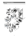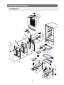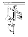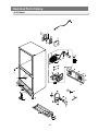
1
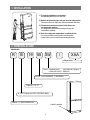
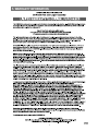
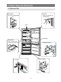
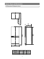
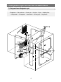
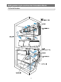
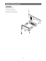
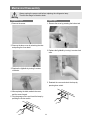
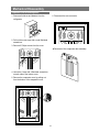
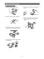
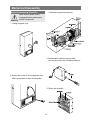
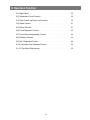
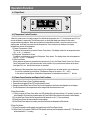
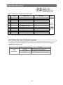
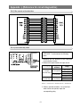
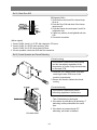
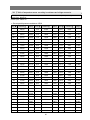
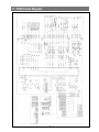
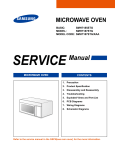
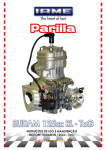
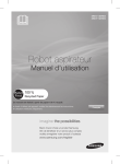
SAMSUNG Home Appliance Service
Bottom-Mounted Freezer
Model:
RB1955SW
RB1955SH
RB1955VQ
RB2155SW
RB2155SH
RB2155BB
WARNING
IMPORTANT SAFETY NOTICE
The service guide is for service men with adequate backgrounds of
electrical, electronic, and mechanical experience. Any attempt to repair a
major appliance may result in personal injury and property damage. The
manufacturer or dealer cannot be responsible for the interpretation of this
information.
SAMSUNG ELECTRONICS AMERICA, INC.
Technical Service Guide
Copyright ⓒ2004
All rights reserved. This service guide may not be reproduced in whole or in
part in any form without written permission from the SAMSUNG ELECTRONICS
Company.
2
Contents
1. Installation
······································
2. Nomenclature
4
····································4
3. Product Specifications
·······························5
4. Electrical part specifications & standard
5. Warranty information
·····················5
································7
6. Interior Views and Dimensions ···························8
7. Refrigeration Cycle and Cool Air Circulation Route···············10
8. Mechanical Disassembly······························12
9. Operation Function ·································19
10. Circuit Descriptions ································26
11. Diagnostics·····································34
12. Illustrated Parts Catalog
·····························48
13. Safety instruction on services
··························56
●
Appendix Ⅰ(Reference for circuit diagnostics)
●
Appendix Ⅱ(Circuit diagram)
·················57
···························61
3
1. INSTALLATION
1) To protect refrigerator in movement
Use padded hand truck from side only.
2) Remove all protective tape and pad from the refrigerators.
Connect power cord. Adjust the clearance between the doors.
3) Temperature controls ard preset in the factory for
recommended settings.
The refrigerator should runs smoothly and lower the
temperature gradually.
4) Once the refrigerator temperature is sufficiently low
It is recommended to store foods in the refrigerator.
It takes a few hours to reach the preset temperatures.
2. NOMENCLATURE
2004 Models
R
B
19
55 SW
/
XAA
Buyer code
COLOR ; SW-SNOW WHITE
SH-STAINLESS PLATINUM
VQ-BISQUE GLOSSY BB-BLACK
OPTION ; 55-NO DISPENSER 77-DISPENSER
Capacity ; CU. FT
B - BOTTOM MOUNTED FREEZER (BMF)
Product ; R - REFRIGERATOR
Label Location
4
3. PRODUCT SPECIFICATIONS
Model
RB1955SW/SH/VQ
RB2155SW/SH/BB
Type
BMF 2 Door
Temperature control
Electronic control
Total
18.7
20.4
Freezer
5.9
6.5
Refrigerator
12.8
13.9
32.3 X 28.3 X 69.9
32.3 X 30.3 X 69.9
Net Capacity
3
(ft )
Net dimension
(W X D X H)
Foam
Cabinet insulation
CYCLO-PENTANE
Door insulation
CYCLO-PENTANE
Cabinet
A.B.S
Door
A.B.S
Liner
227
Net weight(Ib)
241
4. ELECTRICAL PART SPECIFICATIONS & STANDARD
STANDARD
ITEM
Model
RB1955SW/SH/VQ
RB2155SW/SH/BB
Rated Voltage
115V
Frequency
60HZ
Compressor
Model
MK172C-L2U
Starting type
RSCR
Refrigerant
R134a
Oil Charge
Freol α-10c(Ester), 265cc
Freezer
Split Fin & Tube Type
Refrigerator
Split Fin & Tube Type
Evaporator
Condenser
Forced & Natural Convection Type
Dryer
Molecular Sieve XH-9
Capillary tube
ID0.82 X L3000
Earth screw
BSBN(Brass screw)
Door switch
AC125V 1.4A(SSD-6D)
5
ELECTRICAL PART SPECIFICATIONS & STANDARD
ITEM
STANDARD
Temperature
Type
Freezer
F-Sensor
Type
Refrigerator
R-Sensor
Temperature Selection
ON(℉)
OFF(℉)
–14℉
–12.0℉
–16.0℉
–2℉
0℉
–4℉
8℉
10℉
6℉
Temperature Selection
ON(℉)
OFF(℉)
34℉
36℉
32℉
40℉
42℉
38℉
46℉
48℉
44℉
First Defrost Cycle
(Concurrent Defrost of F and R)
Defrosting
4hr ±10min
Defrost Cycle(FRE)
Min. 12hrs, Max. 22Hrs
Defrost Cycle(REF)
Min. 6hrs, Max. 11Hrs
Pause Time
10±2min
Freezer-Sensor
Refrigerator-Sensor
Sensor
FRE Evap-Sensor
THERMISTOR (502AT), SPEC:5.0KΩ AT 77℉
Electrical parts
REF Evap-Sensor
Ambient TEMP-Sensor
Heater
Defrost Heater(FRE)
242W
Drain Heater(FRE)
52W
Defrost Heater(REF)
120W
Drain Heater(REF)
38W
Thermal-Fuse for preventing
overheating of Freezer Defrost-Heater
AC250V 10A 77±5˚C
Fuse
Thermal-Fuse for preventing
overheating of Freezer Defrost-Heater
Capacitor
RUNNING
RSCR 250VAC, 12㎌
MODEL
4TM437RHBYY-53
Over-Load
Protector
TEMP. ON
130±5
TEMP. OFF
69±9
STARTINGMODEL
J531Q33E100M200-2
RELAY
OPERATION
10±20%
FRE.
IS3210-SNP6D
REF.
MOTOR-FAN
IS3208-SNP6H
CIRCUIT
IS3208-SCH6A
FRE(INCANDESCENT)
110V-130V/15W
LAMP
REF(INCANDESCENT)
110V-130/30W
6
5. WARRANTY INFORMATION
7
6. Interior Views and Dimensions
6-1) Shelves and Bins
• Deli drawer
• Door Bin
Pull it out to disassemble.
Push it up and slide it out
to disassemble.
Light
•
•
•
• Gallon Bin
• Glass Shelf
•
Pull it out until its stop
Tilt down and slide it out.
•
• Vegetable Drawer
•
•
• Freezer Drawer
• Ice trays
8
Interior Views and Dimensions
6-2) Dimensions of Refrigerator (Inches)
MODEL
A
B
C
RB1955
RB2155
24.3
28.3
57.8
26.3
30.3
59.8
9
7. Refrigeration Cycle and Cool Air Circulation Route
7-1) Refrigerant Route in Refrigeration cycle
Compressor → Sub condenser → Cluster pipe → Hot pipe → Dryer → Capillary tube
→ R-Evaporator → F-Evaporator → Accumulator → Suction pipe → Compressor
10
Refrigeration Cycle and Cool Air Circulation Route
7-2) Cool Air Circulation
11
8. Mechanical Disassembly
Refrigerator Disassembly
Control Panel
········································
13
Refrigerator Light ······································ 14
Freezer Light
········································
Evaporator Cover in the Refrigerator
··························
15
·····························
16
·································
17
Evaporator Cover in the Freezer
Evaporator in the Freezer
14
Evaporator in the Refrigerator
······························
17
Machine Compartment & Electric Box ··························18
12
Mechanical Disassembly
Control Panel
1. Remove the screws.
2. Pull out the control panel.
3. Disconnect the wire connector.
13
Mechanical Disassembly
Warning
Always unplug the power cord before replacing the refrigerator lamp.
There is the danger of electric shock.
Refrigerator Light
Freezer Light
1. Remove the screw.
1. Remove the cover by pressing the bottom tab.
2. Remove the lamp cover by unlocking the tabs
and pulling the cover down.
2. Replace the lightbulb by turning it counter-clock
wise.
3. Replace the lightbulb by turning it counterclockwise.
3. Reattach the cover and check the lamp by
pressing door switch.
4. After replacing the bulb, reattach the cover
and the screw it again.
5. Plug the power cord in and check the lamp by
pressing the R-door switch.
14
Mechanical Disassembly
Evaporator Cover in the Refrigerator
6. Disconnect the wire connector.
1. Remove all shelves and drawers from the
refrigerator.
2. Pull out the screw caps with a small flat-blade
screwdriver.
3. Remove 6 Phillps screws from the cover.
■Ductwork of the evaporator fan assembly.
4. Unlock the 2 tabs with a flat-blade screwdriver
on each side of the bottom cover.
5. Remove the evaporator cover by pulling out
from the bottom of the evaporator cover.
15
Mechanical Disassembly
Evaporator Cover in Freezer
5. Disconnect wire connector from the top-left
corner.
1. Remove all drawers from the freezer.
2. Remove screws (2) from the support rail.
6. Remove 2 screws from the rear cover of the
freezer evaporator and unlock the tabs to
remove it.
2 screws
3. Pull down the holder of the support rail and
disconnect the wire connector to remove it.
①
②
4. Unlock the tabs around the evaporator cover
from the buttom.
②
③
①
16
Mechanical Disassembly
Evaporator in Refrigerator
Evaporator in Freezer
Evaporator is located in the bottom of refrigerator.
1. Take off the ductwork in refrigerator.
2. Disconnect the wire connector.(Heater and
Thermistor)
3. Desolder the capillary tube and the suction line
from the evaporator.
4. Remove the evaporator.
5. With a file, score the capillary tube just
upstream of the soldered point. Break off the
soldered section to help prevent solder from
plugging the tube during soldering.
6. Place a new evaporator and braze the suction
and capillary tube to evaporator using silver
solder.
7. Install a replacement dryer.
8. Evacuate and recharge the system using
reasonable procedures.
Evaporator is located in the bottom of freezer to
produce cold air driven across the evaporator coils.
1. Take off the ductwork in Freezer.
2. Disconnect the wire connector (Heater,
Bimental, and Thermistor).
3. Desolder the inlet and outlet tubes.
4. Remove the evaporator.
5. Take the same steps to seal the system as
mentioned earlier.
Accumulator
Thermal
Fuse
Thermal
Fuse
Thermistor
Thermistor
17
Mechanical Disassembly
Machine Compartment & Electric Box
3. Mechine compartment assembly
Make sure the power cord is
unplugged before replacing any
Warning electric components.
1. Unplug the power cord.
4. Disassemble the electric box cover after
removing the screws with a Phillips screwdriver.
2. Remove the screws of the compartment cover.
Slide it up and take out from the refrigerator.
5. Electric box assembly
18
9. Operation Function
9-1) Digital Panel
···································20
9-2) Temperature Control Function
·························20
9-3) Power Freeze and Power cool Functions
··················· 20
21
9-4) Sound Function
·································
9-5) Defrost Function
································· 21
9-6) Forced Operation Function ··························· 22
9-7) Power failure compensating Function ····················· 23
9-8) Exhibition Function
·······························
23
9-9) Self - Diagnostics Function ··························· 23
9-10) Component Load Operation Function. ···················· 24
9-11) C-Fan Motor Delay function ·························· 25
19
Operation Function
9-1) Digital Panel
9-2) Temperature Control Function
When the system power is initally engaged, the default set temperature are -2℉ for the freezer and 38℉ for
the set refrigerator, respectively. The numbers shown on the digital display panel stand for the actual
compartments temperatures. When the compartment temperatures go down, so do the numbers on the
display panel, and finally they reach the set temperatures. Once the system is stabilized, the display
temperatures are the set temperature.
1) Freezer Temperature Control.
To select a set temperature, press the Freezer Temp. button. The display shows the set temperature from 14℉ to 8 ℉ in sequence.
2) Refrigerator Temperature Control.
To select a set temperature, press the Refrigerator Temp. button. The display shown the set temperature
from 34℉ to 46℉ in sequence.
3) Child Lock Button
When these two buttons are pressed at the same time for 3 sec., the Power Freeze, Power Cool, Freeze
Temp, Refrigerator Temp, are locked and can not be modified. If you press the two buttons at the same
time again for 3 sec., the child lock function is cancelled.
note) Because of the temperature sensor sensivity, the refrigerator can be under and/or over cooled when
the air flow is blocked by stored foods. (Temperature range of the sensor : 15℉∼80℉)
In the event of a power failure, if the freezer temperature is maintained lower than 41℉, the last
9-3) Power Freeze Function and Power Cool Functions.
●
●
●
●
Select the Power Freeze or Power Cool buttons separately.
These buttons are toggled ON and OFF and the indicators as well.
Although you select Power Freeze or Power Cool, the set temperatures in the freezer and refrigerator are not changed.
The set temperatures for the compartments can be changed while these functions are in use.
1) Power Freeze function
1-1) When you press the Power Freeze button, the LED indicator lights right away, but there is 10 seconds lag time to an
actual operation. When this button is pressed again, the Power Freeze function stops and the indicator is off immediately .
1-2) If you select Power Freeze, both the compressor and the freezer fan run for 2 ½ hours continuously.
1-3) During Power Freeze, the freezer retains the current settings.
1-4) When Power Freeze expires, the indicator goes off and the freezer set temperature will be restored.
2) Power Cool function
2-1) Power Cool operation and the indicator work exactly same as the Power Freeze function.
2-2) When Power Cool is selected, COMP and R-FAN operate continuosly until the refrigerator reaches 25℉. This function will
be terminated after 2 ½ hr running.
20
Operation Function
3) When you select Power Freeze and Power Cool together
Each function works at the same time. The COMP and F-FAN run continuously and the R-FAN runs until 25℉
in the refrigerator.
4) Initial Power-On
4-1) When the freezer and the refrigerator temperatures are higher than 14℉ and 50℉, respectively, if Power Freeze is
selected, then the R-FAN will be off. If Power Cool is selected, then the F-FAN will be off.
4-2) When both functions are selected, there is no benefit of fast cooling for each compartment.
9-4) Sound Function
1) Sound function
1-1) To make sure a command input, whenever a button is pressed, a “ding-dong” sounds.
1-2) When two or more buttons are pressed simultaneously or if a wrong button is pressed, there is no
sound.
2) Door Open Alarm
2-1) When the doors remain open for 2 minutes, there are 10 times beeps.
2-2) If the doors continue to remain open more than 2 minutes, the additional 10 beeps interval will change to
1 minute.
2-3) The beeps will cease immediately when the doors are closed.
9-5) Defrost Function
1) A defrost is determined based on the accumulated compressor on-time.
2) When the power is engaged for the first time, the defrost cycle for the freezer and the refrigerator will begin
after 4 hours of the accumulated compressor on-time.
3) A defrost interval depends on the ambient temperature, the number of door openings, and the door open
time.
4) The defrost cycle is composed of a pre-cool process (F-Fan and COMP) for 30 minutes, a heating
process, and a resting for 8-12 minutes to drain.
5) A minimum interval is 6 hours and a maximum is 11 hours for the refrigerator, and 12 hours and 22 hours
for the freezer, respectively.
6) When the system runs only for the refrigerator (R-Fan and COMP) and if the refrigerator can not reach the
set.
21
Operation Function
9-6) Forced Operation function (Power cool key + Refrigerator. Temp 8sec.)
This function enables a pull-down mode, a defrost mode for the refrigerator only, a defrost
mode rigerator at the same time, and a cancellation of this function.
● Press Power Cool and Refrigerator Temp. buttons for 8 seconds simultameously to get in the
ready mode for a forced operation.
● The display panel will return to normal after 15 seconds in the ready mode.
● At the ready mode, press any button once to start a pull-down operation, twice for a defrost
cycle for the refrigerator, three times for a defrost cycle for the freezer and the refrigerator, and
finally four times for cancellation of this function.
● Another way to cancel this function is to simply plug out and in the power cord.
●
1) Pull-down Operation
1-1) At the ready mode, press any button once then the buzzer will beep (ON for 1/2 second and
OFF for 1/2 second) until this mode is cancelled.
1-2) At this pull-down mode, the compressor will start immediately (No 5 minute delay) and if the
system is in the defrost cycle, it will be cancelled right away.
note) If this pull-down mode begins right after the compressor was off, the compressor may not
start to run due to an overload condition.
1-3) At this mode, the compressor and freezer fan will operate continuously for 24 hours and the
refrigerator fan will be on and off according to the set temperature(34℉)
1-4) After 24 hour operation, the system will be cycled at -14℉ for the freezer and 34℉ for the
refrigerator.
1-5) In order to cancel this mode at any time, select the next mode on the ready mode or power
off the system.
2) Defrost operation
2-1) At the pull-down mode, press any button again on the ready mode to begin the defrost cycle
for the refrigerator.
2-2) The beep sound continues for 3 second at the beginning, then ON for 3/4 seconds and OFF
for 1/4 second until this mode cease.
2-3) After this operation, the system will come back to normal operation.
2-4) At this mode, press any button again on the ready mode to operate the defrost cycles for
both compartments.
2-5) The beep sound continues for 3 seconds at that time, then ON for 1/4 second and OFF for
3/4 seconds until the defrost operation cease.
3) Cancellation
3-1) At the R,F-Defrost mode, press ant button again on the ready mode to return to a normal
operation.
3-2) Simply unplug the power cord, then plug it again to return to a normal operation.
22
Operation Function
9-7) Power failure compensating function
1) When the freezer temperature is lower than 50℉, all functions on the display panel will be restored.
2) When the freezer temperature is higher than 50℉, all functions will be initialized.
(2℉ for the freezer, 38℉ for the refrigerator, and Cubed for the Ice Type)
9-8) Exhibition Function
l
This function is for a display purpose on the floor of show room or store.
1) Mode ON/OFF
1-1) For the exhibition mode, press Power Freeze and Freezer Temp. buttons simultaneously for 5
seconds until a “ding-dong” sounds.
1-2) Press the same time buttons again for 5 seconds to cancel this mode put with a “ding-dong”
sound.
2) Operation
2-1) Most of the system function except the compressor operation are working properly.
2-2) There is no defrost cycle in this mode.
9-9) Self-Diagnostics function
1) Self-Diagnostics in the initial Power ON
1-1)The control board performs a self diagnostics test within 1 second and check out the temperature
sensors abilities.
1-2) If a sensor failure occurs, a corresponding LED segment will blink.
1-3) When a LED segment blinks, only the cancellation function (Press Power Freeze and Power Cool
buttons simultaneously for 8 seconds) is acceptable.
1-4) After a replacement of bad sensor or a cancellation of this function, this self diagnostics will end.
2) Self-Diagnostics in the normal operation
2-1) To select this function, press Power Freeze and Power Cool buttons simultaneously for 5 seconds
with an audible tone.
2-2) In the self diagnostic mode, only corresponding LED segments will be illuminated (see the check
list on)
2-3) After a 30 second illumination of error signal, the system will return to the normal operation.
23
Operation Function
Table 1. Display table of self diagnosis.
No
Item
LED Display
Details
Remarks
1
R-sensor
REFRIGERATOR
• Connector contact failure
• Short-circuit
•Suspected to be below -58℉
•Suspected to be over 150℉
2
R-defroster
sensor
REFRIGERATOR
• Connector contact failure
• Short-circuit
•Suspected to be below -58℉
•Suspected to be over 150℉
3
Outer sensor
FREEZER
• Connector contact failure
• Short-circuit
•Suspected to be below -58℉
•Suspected to be over 150℉
F-sensor
FREEZER
4
• Connector contact failure
• Short-circuit
•Suspected to be below -58℉
•Suspected to be over 150℉
FREEZER
5
F-defroster
sensor
• Connector contact failure
• Short-circuit
•Suspected to be below -58℉
•Suspected to be over 150℉
9-10) Component Load Operation Function
1) In the normal operation, press Power Freeze and Power Cool buttons simultaneously for 3 second,
then the display panel will blink for 2 seconds.
2) Press Refrigerator Temp. button to get into this check mode with an audible tone.
3) Each illuminating LED segment stands for the component which has an ouput signal from the control
board.
4) This mode will terminate automatically after 30 seconds.
24
Operation Function
FREEZER:10digit
FREEZER: 1digit
REFRIGERATOR:10digit
REFRIGERATOR: 1digit
Table 2. Display table of the presently operating parts.
No
Content
1
2
3
4
5
6
7
8
9
10
11
R-fan
R-defrost heater
Initial start mode
Over load mode
Low temp.mode
Exhibition mode
Comp
F-fan
F-defrost heater
F-Lamp
R-Lamp
Display LED
Operation
Include R-fan activation
Defrost heater activation
Initial power is activated ON
Outer temperature is over 95℉
Outer temperature is below 68℉
Exhibition mode is operated together
Led ON when COMP activation is included
Led ON F-fan activation is included
Led ON when F-heater activation is included
Led ON when F-lamp activation is included
Led ON when R-lamp activation is included
a : REFRIGERATOR 1 digit
c : REFRIGERATOR 1 digit
d : REFRIGERATOR 1 digit
e : REFRIGERATOR 1 digit
f : REFRIGERATOR 1 digit
g : REFRIGERATOR 1 digit
a : FREEZER 1 digit
b : FREEZER 1 digit
d : FREEZER 1 digit
a : FREEZER 10 digit
b : FREEZER 10 digit
Remark
Ref. 6.button scan
and display circuitry
※ 3, 4, and 5 only explains the system operation states according to the ambient condition.
9-11) C-Fan Motor Delay Function of the Machine Compartment
l
According to the ambient temperature, the condenser fan located in the machine compartment is
operated with different modes.
C-FAN
Delay function
Operation
Ranges of ambient temp.
C-FAN is ON as soon as the compressor is on.
Above 66℉
C-FAN is ON with 5 minutes delay from the compressor on.
61℉ ~ 65℉
C-FAN is OFF regardless of the compressor operation.
Below 60℉
25
10. Circuit Descriptions
10-1) Source Power Circuit
································
27
···································
27
·····································
28
10-2) Oscillator Circuit
10-3) Reset Circuit
10-4) Door S/W Sensing Circuit ······························ 28
10-5) Temperature Sensing Circuit ···························· 29
10-6) Key Scan and Display Circuit ···························· 30
10-7) Load Drive Circuit
··································
31
10-8) Option Circuit ····································· 32
26
Circuit Descriptions
10-1) Source Power Circuit
Circuit used
Voltage
(DC 12V)
Relay Operation & LED Display
Vcc (DC 5V)
Power around MICOM & Sensor Detector
1) The input AC voltage drops to AC 8 volts on the transformer secondary side between ①~③ at CN
10. The rectified voltage passed through D101 ~ 104 becomes DC 5V through voltage regulator
MC7805(REG1).
This (DC5V) is supplied to the control board and sensor’s circuits.
2) The input AC Voltage drops to AC 15 volts on the transformer secondary side between ⑤~⑦ at
CN 10. The rectified voltage passed through D105 ~ D108 becomes DC 12V through voltage
regulator MC7812CT (REG2).
This (DC12V) is supplied to the relay operation and LED display.
10-2) Oscillator circuit
Port
Oscillating Frequency
Xin(#19)
4.00MHz
Xout(#20)
4.00MHz
It is designed for clock generation and time
calculation for synchronizing transmission and
reception on the logic elements inside the MICOM.
If the X-TAL specification changes, MICOM may
make an error.
(The standard components should be used.)
±0.5% Error
27
Circuit Descriptions
10-3)Reset Circuit
Port
Voltage
Vcc
DC 5V
Reset
DC 5V
When the power is supplied to MICOM, the reset
circuit initializes RAM and other sectors of MICOM.
A reset voltage maintains “low” for hundreds of µsec
comparing to MICOM Vcc voltage when the power is
in. It also maintains “high”(5V) during normal
operation. But, when Vcc drops to 3.4V-3.7V, a reset
port becomes “low”.
10-4) Door S/W Sensing Circuit
DOOR
Door Conditions
Door S/W Contact
MICOM
PIN NO
“HIGH”
CLOSE
OPEN
OPEN
CLOSE
CLOSE
OPEN
F
# 39
“LOW”
“HIGH”
R
# 40
OPEN
Micom Input Voltage
CLOSE
“LOW”
1) If a door is open, the door S/W contact is closed. Then MICOM receives “low” signal and
detects door open, A relay control circuit receives “HIGH” signal and turn Lamp on.
2) If a door is closed, the door S/W contact is open. Then MICOM receives “high” signal and
detects door close, A relay control circuit receives “LOW” signal and turn Lamp off.
28
Circuit Descriptions
10-5) Temperature Sensing Circuit
( Air Sensor)
When Sensor is open
When sensor is cut off
MICOM input “HIGH”
MICOM input “LOW”
1) The sensor uses the characteristics of thermistor. If temperature goes higher, resistance goes
lower. On the contrary, if temperature goes lower, resistance goes higher.
2) A MICOM input voltage is calculated by sensor as follows.
RTH
(VCC : 5V, RTH : Sensor reisitance)
VF =
X Vcc
RTH + R301
3) For the resistance data corresponding to a temperature and a MICOM input voltage, please
refer the conversion table on the back.
29
Circuit Descriptions
10-6) Key Scan and Display Circuit
If the IC04 decorder(KID65783AD) receives signals from MLCOM pins(34-6), an output signal per
2 miliseconds comes out from Grid#1-#7. A step DC12 volt peak will be generated periodically as
follows:
30
Circuit Descriptions
10-7) Load Drive Circuit
1) Most of relays can control the compressor, heaters and several option functions.
2) For the compressor, #12 pin of MICOM signals HIGH(5V). This signal enters to #2 of IC03 and #15
of output terminal will be on and grounded. When the rely RY71 is switched to NO terminal a 115V
power is supplied to the compressor. If MICOM outputs LOW(0V), the compressor will stop.
3) If the RY71 is connected to NC, RY72 and 73 for defrost heaters will be on and corresponding heater.
RELAY
Load
Remark
off
Comp Operation
Defrost-Heater Power Off
on
on
Comp off, Defrost-Heater Off
off
on
Defrost-Heater On
off
off
Comp Off, Defrost-Heater Off
COMP
Defrost Heater
on
Comp Power Off
Will be activated according to the signal from MICOM. Like the above block diagram, operation of F,
R defrost heater is determined by the operation of the relay for COMP.
31
Circuit Descriptions
10-8) Option Circuit
Temperature and function values can be abjustable by using main PCB switching diode.
• Note : the values have been preset in factory. If is recommended not to change the value arbitrarily.
When the option function is modified, a power should be turned off and on, again.
1) Freezer Temperature Shift
2) Refrigerator Temperature Shift
(Unit ˚F)
(Unit ˚F)
SHIFT
D601
D602
D603
SHIFT
D604
D605
D606
Reference
-
-
-
Reference
-
-
-
-1.0
-
-
•
-1.0
-
-
•
-2.0
-
-4.0
-
-6.0
+2.0
+4.0
+6.0
•
•
•
•
•
•
-
-2.0
-
•
-4.0
-
-
-
-6.0
-
•
+2.0
-
+4.0
•
+6.0
•
•
32
•
•
•
•
•
•
•
-
-
-
•
•
•
-
-
•
Circuit Descriptions
33
11. Diagnostics
11-1) If power is not ON
Caution!
At the power of main PCB, the 115V power and a highvoltage over DC 170V occur. Special care should be
advised on repair and measurement.
34
To check the main PCB,
please apply descriptions of
operation and references in
the manual.
Diagnostics
11-2) If there is a trouble with self-diagnosis
1) If the ambient sensor has trouble.
2) If the temperature sensor of the refrigerator has trouble.
35
Diagnostics
3) If the defrost sensor of the refrigerator has trouble.
4) If the temperature sensor of the freezer has trouble.
36
Diagnostics
5) If the defrost sensor of the freezer has trouble.
37
Diagnostics
11-3) If the compressor is not working properly
Pre-check
1. A compressor does not operate within 5 minutes after compressor is OFF.
2. A compressor does not run during defrost period
3. A compressor does not run because a low temperature is detected if freezer and the
refrigerator sensor are not connected.
38
Diagnostics
11-4) If cooling fan doesn’t work
Pre-check
Select a pull-down mode from the forced operation function
1. When COMP is OFF both freezer and the refrigerator cooling fans and COMP cooling fan
remain OFF.
2 . When COMP is ON, the refrigerator fan is not always ON and when the refrigerator
temperature reached a set temperature, the fan goes OFF.
3. When both the freezer and the refrigerator doors are closed, each fan has a delay time
(5sec ~ 1 min) and then degins to run. (COMP ON condition)
4-1) When freezer fan (F-fan) do not operate
39
Diagnostics
11-5) If the refrigerator fan doesn’t work
40
Diagnostics
11-6) If the compressor cooling fan motor doesn’t work
41
Diagnostics
11-7) No defrosting
Pre-check
1. Although both F R-defrost sensors have short-circuit, a normal operation continues
without a defrost cycle (Refer to self - diagnostics function)
2. When the temperature fuse is open, there is no heating and a defrost occurs naturally by
the compartment temperature increase and eventually, it will cause a blinking of
temperature.
3. When both F R-defrost sensors are open, heating does not end. The compressor remains
off and a temperature fuse will be open. (Refer to self-diagnostics function.)
42
Diagnostics
43
Diagnostics
11-8) Alarm continuously
Pre-check
1. Alarm begins after 2 minutes when the door is open and runs in every 2 minutes.
2. If the door is not closed properly, MICOM will indicate that the door is open, and alarm
continues. If the alam goes for 10 minutes, the light in the compartment will be off and not
be on in the situation that the door opens.
1) If melody sounds continuously
44
Diagnostics
2) If beep sounds continuously
3) When the digital panel PCB does not light
45
Diagnostics
4) When a button of the digital panel is not selected
46
Diagnostics
Pre-check
1. Is the power cord connected to a wall outlet correctly?
2. Be careful of high-voltage, high-frequency discharge from the electronic ballast.
5) If the lamp of refrigerator fails to light
47
12 . Illustrated Parts Catalog.
12-1) Freezer
48
Illustrated Parts Catalog.
■ Parts List of Freezer
NO
CODE-NO
1
2
3
DA67-40203N
DA67-40182A
DA97-00682A
DA97-00682B
DA63-01260A
DA97-00683A
DA97-00683B
DA63-01272A
DA97-00684A
DA97-00684B
DA63-01259A
DA66-10104A
DA71-20145A
DA63-00904B
DA63-00922B
DA97-00181A
DA97-00192F
DA47-00095E
DA32-00006C
DA97-00122E
DA97-00122F
DA61-70114B
DA61-70115C
DA63-40006A
DA63-00924A
DA63-00923A
DA47-00069C
DA32-10105S
4713-001035
DA97-00390D
DA63-00903A
DA61-00081B
DA31-00019A
DA31-00002V
DA63-00771A
DA97-00195D
4
5
6
7
8
9
10
11
12
13
14
15
16
17
18
19
20
21
22
23
24
25
26
27
28
29
30
OPTION
PART NAME
TRAY-ICE,ASSY
TRAY ICE
TRAY-FRE UPP,ASSY
TRAY-FRE UPP,ASSY
COVER-TRAY FREE, UPP
TRAY-FRE MID,ASSY
TRAY-FRE MID,ASSY
COVER-TRAY FREE, MID
TRAY-FRE LOW,ASSY
TRAY-FRE LOW,ASSY
COVER-TRAY FREE, LOW
ROLLER FRE
FIXER ROLLER
TRAY ICE CUBE
TRAY ICE CUBE
COVER EVAP FR(FRE),ASSY
EVAP-FRE ASSY
ASS’Y-FUSE THERMO(77˚C)
SENSOR ASSY
ASSY SUPT-FREE
ASSY SUPT-FREE
SUPPORT-FREE,L
SUPPORT-FREE,R
GROMMET RAIL
COVER-LAMP,FRE
COVER-LAMP,FRE
LAMP HOLDER
SENSOR ASSY
LAMP-INCANDESCENT
COVER-EVAP RE(FRE),ASSY
COVER-EVAP REAR
CASE-MOTOR
FAN-PROPELLER
MOTOR-FAN
GROMMET-FAN MOTOR
DRAIN PLATE FRE ASSY
49
RB1955
RB2155
l
l
l
l
l
l
l
l
l
l
l
l
l
l
l
l
l
l
l
l
l
l
l
l
l
l
l
l
l
l
l
l
l
l
l
l
l
l
l
l
l
l
l
l
SPEC
l
l
l
l
l
l
l
l
l
l
l
l
l
l
l
115V/242W
EVAP FRE.250V
EVAP FRE
110~130V
110~130V
ASSY SUPT-FREE
ASSY SUPT FREE
110~130V/15W
115V
115V,60HZ
115V/52W
Illustrated Parts Catalog.
12-2) Refrigerator
50
Illustrated Parts Catalog.
■ Parts List of Refrigerator
NO
CODE-NO
1
DA97-00681A
DA97-00681B
DA63-01270A
DA64-00656A
DA66-10104A
DA71-20145A
DA61-00761A
DA61-00760A
DA97-00663A
DA97-00663B
DA64-00449A
DA64-00448A
DA67-00505L
DA67-00505M
DA97-00664A
DA97-00664B
DA97-00664C
DA97-00664D
DA64-00450A
DA64-00451A
DA67-00505J
DA67-00505K
DA61-00368A
DA61-00367A
DA61-00370A
DA61-00369A
DA63-00945A
DA97-00296D
DA63-00925A
DA67-40250E
4713-001145
DA96-00017C
DA32-00006C
DA47-00095D
DA97-00459F
DA63-00933A
DA63-00932A
DA63-00183B
DA31-00016A
DA63-00934B
DA64-00452C
DA60-00033A
DA31-00003N
DA63-00771A
DA32-10105T
DA62-00106A
DA62-00109A
DA97-00441B
2
3
4
5
6
7
8
9
10
11
12
13
14
15
16
17
18
19
20
21
22
23
24
25
26
27
28
29
30
31
32
33
34
35
36
PART NAME
CASE-VEG,ASSY
CASE-VEG,ASSY
COVER-VEG
KNOB-HUMIDITY
ROLLER FRE
FIXER ROLLER
RAIL-VEG, MID
RAIL-VEG, MID
COVER-VEG ASSY
COVER-VEG ASSY
TRIM-COVER,VEG
TRIM-COVER,VEG
SHELF GLASS
SHELF GLASS
SHELF REF-MID,ASSY
SHELF REF-MID,ASSY
SHELF REF-UPP,ASSY
SHELF REF-UPP,ASSY
TRIM-SHELF REF
TRIM-SHELF REF
SHELF GLASS
SHELF GLASS
RAIL-CHILLED,L
RAIL-CHILLED,L
RAIL-CHILLED,R
RAIL-CHILLED,R
TRAY CHIL ROOM-ASSY
TRAY CHIL ROOM-ASSY
COVER-LAMP REF
TRAY-UTILTY
LAMP-INCANDESCENT
EVAP-REF ASSY
SENSOR ASSY
ASSY-FUSE THERMO(R)(77˚C)
COVER-EVAP REF ASSY
COVER-EVAP FR REF
COVER-EVAP RE REF
COVER-MOTOR
FAN-CIRCUIT
COVER-SENSOR REF
TRIM-COVER SENSOR
SPACER-DUCT
MOTOR-FAN
GROMMET-MOTOR
SENSOR ASSY
SEAL-COVER EVAP RE
SEAL AIR SIDE
PLATE-DRAIN REF ASSY
51
OPTION
RB1955
RB2155
SPEC
l
l
l
l
l
l
l
l
l
l
l
l
l
l
l
l
l
l
COVER VEG
COVER VEG
l
l
l
l
l
l
l
l
l
l
l
l
SHELF(MID/UPP)
SHELF(MID/UPP)
SHELF(MID/UPP)
SHELF(MID/UPP)
SHELF-UPP
SHELF-UPP
SHELF-UPP
SHELF-UPP
l
l
l
l
l
l
l
l
l
l
l
l
l
l
l
l
l
l
l
l
l
l
l
l
l
l
l
l
l
l
l
l
l
l
l
l
l
l
l
l
l
l
130V, 30W
115V, 120W
EVAP-REF
EVAP-REF, 250V
115~127V, 60Hz
220V~240/50Hz
115V
COVER EVAP
115V/38W
Illustrated Parts Catalog.
12-3) Disassembly of Door
52
Illustrated Parts Catalog.
■ Parts List of Freezer Door
1
2
3
4
5
6
7
8
9
10
11
12
13
14
15
16
17
18
19
20
21
22
23
24
CODE-NO
PART NAME
DA91-01768C
DA91-01768D
DA91-01768E
DA91-01768F
DA71-40135A
DA71-40183C
DA71-40183P
DA71-40183Q
DA71-40183R
DA91-01767C
DA91-01767D
DA91-01767E
DA91-01767F
DA63-01052A
DA63-00926B
DA63-00927B
DA63-01262A
DA63-01263A
DA61-00365B
DA61-00378A
DA61-00361A
DA63-50145A
DA67-00546A
DA67-00546G
DA67-00546H
DA67-00546J
DA61-10153E
DA61-10142C
DA63-50139C
DA97-00352X
DA97-00352Y
DA97-00352Z
DA97-00352W
DA63-00909F
DA63-00909J
DA63-00909K
DA63-00909L
DA64-00444A
DA64-00445A
DA63-00915A
DA63-00916A
DA41-00225A
ASSY FOAM-DOOR REF
ASSY FOAM-DOOR REF
ASSY FOAM-DOOR REF
ASSY FOAM-DOOR REF
STOPPER DOOR, MID
STOPPER DOOR, LOW
STOPPER DOOR, LOW
STOPPER DOOR, LOW
STOPPER DOOR, LOW
ASSY FOAM-DOOR FRE
ASSY FOAM-DOOR FRE
ASSY FOAM-DOOR FRE
ASSY FOAM-DOOR FRE
GASKET-DOOR SUB FRE
GUARD-REF UPP, L
GUARD-REF UPP, R
GUARD-REF MID
GUARD-REF LOW
GUIDE-BOTTLE
HINGE-UPP ASSY
HINGE-UPP
SHIM-HINGE UPP
CAP HINGE UPP
CAP HINGE UPP
CAP HINGE UPP
CAP HINGE UPP
HINGE-MID, ASSY
HINGE-MID
SHIM-HINGE MID
ASSY COVER CONTROL PANEL
ASSY COVER CONTROL PANEL
ASSY COVER CONTROL PANEL
ASSY COVER CONTROL PANEL
COVER CONTROL PANEL
COVER CONTROL PANEL
COVER CONTROL PANEL
COVER CONTROL PANEL
BUTTON-PCB, L
BUTTON-PCB, R
GASKET BUTTON PCB, L
GASKET BUTTON PCB, R
PANEL PCB
OPTION
RB1955SW/2155SW RB1955VQ
RB2155BB RB1955SH/2155SH
l
l
l
l
l
l
l
l
l
l
l
l
l
l
l
l
l
l
l
l
l
l
l
l
l
l
l
l
l
l
l
l
l
l
l
l
l
l
l
l
l
l
l
l
l
l
l
l
l
l
l
l
l
l
l
l
l
l
l
l
l
l
l
l
l
l
l
l
l
l
l
l
l
l
l
l
l
l
l
l
53
l
l
l
l
l
l
l
l
l
l
l
l
l
l
l
l
SPEC
SNOW WHITE
BISQUE
BLACK
STAINLESS PLATINUM
SNOW WHITE
BISQUE
BLACK
STAINLESS PLATINUM
SNOW WHITE
BISQUE
BLACK
STAINLESS PLATINUM
SNOW WHITE
BISQUE
BLACK
STAINLESS PLATINUM
SNOW WHITE
BISQUE
BLACK
STAINLESS PLATINUM
SNOW WHITE
BISQUE
BLACK
STAINLESS PLATINUM
SILVER
SIVLER
Illustrated Parts Catalog.
12-4) Cabinet
54
Illustrated Parts Catalog.
■ Parts List of Cabinet
CODE-NO
1
2
3
4
5
6
7
8
9
10
11
12
13
14
15
16
17
18
19
20
21
22
23
24
25
26
27
28
29
30
31
32
33
DA61-10145D
DA64-20138B
DA63-10262F
DA63-10262R
DA63-10262S
DA63-10262T
DA34-00122D
DA61-00758A
DA67-30218R
DA67-00322M
DA67-00322N
DA67-00322G
DA26-30111J
2501-001045
DA63-01271A
DA41-00128D
DA63-00951A
DA63-00951B
DA62-20001Q
DA97-00408B
DA31-00010B
DA31-10110G
DA73-10109A
DA97-00180N
DA63-40171B
DA63-40171D
DA73-10314L
DA65-20101B
MK172C-L2U
DA73-30102B
DA34-10003D
DA35-10013N
DA63-10352A
DA71-60141D
DA61-40101C
DA60-90124A
DA61-00178A
DA63-40004A
DA62-00217A
PART NAME
OPTION
RB1955SW/2155SW RB1955VQ
l
l
l
HINGE-LOW
TRIM-PLATE, ABSORBER
COVER-LEG
COVER-LEG
COVER-LEG
COVER-LEG
SWITCH DOOR
CASE-PCB PANEL
CAP-SCREW
CAP-SCREW
CAP-SCREW
CAP-SCREW
TRANS POWER
C-OIL
COVER-PCB PANEL
PBA-MAIN
GROMMET-DRAIN HOSE, A
GROMMET-DRAIN HOSE, B
TUBE-PVC
COVER-COMP ASSY
FAN-ASY
MOTOR-CIRCUIT
PIPE-CONNECT
TRAY-DRAIN WATER ASSY
GROMMET-SUCT PIPE, A
GROMMET-SUCT PIPE, B
PIPE-SUB COND ASSY
CLAMP-COMP
COMPRESSOR
DRYER-ASSY
PROTECTOR O/L
RELAY-PTC
COVER RELAY
CHASSIS-COMP ASSY
CASTER-REAR
RIVET-CASTER
LEG-ASSY
GROMMET COMP
SEAL-SUB COND
l
l
l
l
l
l
l
l
l
l
l
l
l
l
l
l
l
l
l
l
l
l
l
l
l
l
l
l
l
l
l
l
l
l
l
l
l
l
l
l
l
l
l
l
l
l
l
55
l
l
l
l
l
l
l
l
l
l
l
l
l
l
l
l
l
l
l
l
l
l
l
l
l
l
l
SPEC
RB2155BB RB1955SH/2155SH
l
l
l
l
l
l
l
l
l
l
l
l
l
l
l
l
l
l
l
l
l
l
l
l
l
l
l
l
l
l
l
l
l
l
l
l
l
l
l
l
l
l
l
l
l
l
l
l
l
l
l
l
l
l
l
SNOW WHITE
BISQUE
BLACK
STAINLESS PLATINUM
SNOW WHITE
BISQUE
BLACK
STAINLESS PLATINUM
115V
250V, 12uF
115V
REF(¢10)
FRE
115V/60Hz
115V
PIPE-SUB COMA
PIPE-SUCT
R134a
4TM437RHBYY-53
J531Q33E100M200-2
13. Safety Instructions on Service
●Unplug the refrigerator before making any repair or any replacement.
Avoid the electric shock.
●Use the rated components on the replacement.
Check the correct model number, rated voltage, rated current, operating temperature and so
on.
●On repair, be sure that the wires such as harness are bundled tightly and are not exposed by
water.
Bundle wires tightly in order not to be detached by the external force.
●On repair, remove completely dust, particles or other things on housing parts, harness parts,
and connectors.
Cleaning may prevent fire by tracking or short.
●Check if there is any trace indicating the infitration of water on electrical parts.
If there is a trace, change the related components or do the necessary action
such as taping using the insulating tape.
●After repair, check the assembled state of parts.
It must be the same assembled state as before.
●Check the surrounding conditions of the installed refrigerator.
When the refrigerator is located at humid or wet place, or the installed state is
unstable, change the location.
●If needed, do the ground.
Especially, if there is a possibility of the electric leakage, this appliance must be
properly grounded.
●Do not allow consumers to use one outlet for several plugs.
●Check if the power cord is placed under other appliance and so was damaged, worm-out and
squeezed.
Repair defective power plug or outlet immediately.
Make sure that the power cord is not placed under other appliance or squeezed.
●Do not allow consumers to keep bottles or the likes in the Freezer or to keep foods in unstable
position.
●Do not allow consumers to repair the appliance by themselves.
●Do not allow consumers to keep other chemicals except food.
Medicines and other materials for research ; This appliance will not maintain the precisely
constant temperature for them.
Volatile material(Alcohol, Benzene, Ether, LP gas etc.) : possibility of explosion
56
Appendix Ⅰ(Reference for circuit diagnostics)
Ref.1) Wire connector on the cabinet door.
Ref. 2) How to check relay failure
* Disconnect the wire connector from the main
PCB CN70, 71 and measure the following
items.
1. Measure the coil bisection of the relay and
check whether it works.
2. Measure the apex bisection for open circuit.
Category
Voltage of coil
terminal
3-contact
terminal Relay
DC 12V(Operation)
DC 0V(Standstill)
2-contact
terminal Relay
DC 12V(Operation)
DC 0V(Standstill)
Judge
C-NO:SHORT
C-NC:OPEN
C-NO:OPEN
C-NO:SHORT
SHORT
OPEN
Note) C → Common, NO → Normal open, NC → Normal close
3. When it operates as above, it is normal and
when it does not operate, repair the
corresponding relay.
57
Ref. 3) Check a load
* Unplug the power cord and disconnect the
connector from the main PCB CN70, 71 and
measure the following:
1. Measure resistance between the terminals and
check for malfunctioning of a load and wire
connection.
Subordinate
R Defrost heater
F Defrost heater
Comp
Comp-circulation fan
R-Circulation fan
F-Circulation fan
R-Lamp
F-Lamp
Measurement Evaluation of meaterminal
surement result
CN70 ⑤ - ①
CN70 ⑦ - ①
CN70 ⑨ - ①
CN71 ⑦ - ①
CN71 ⑤ - ①
CN70 ③ - ①
CN71 ⑨ - ①
CN71 ③ - ①
Ref. 4) Check sensors
* Disconnect the connector from the main PCB
CN30.
* Resistance will be lowered while the
temperature rises due to a NTC type sensor.
1. R sensor measures resistance of CN30
between ②~⑤.
2. Freezer sensor measures resistance of CN30
between ①~⑤.
3. R-defrost sensor measures resistance of CN30 between ④~⑤.
4. F-defrost sensor measures resistance CN30 between ③~⑤.
5. The measured value above is compared to the sensor specification and the temperature table in
speciication found in the manual.
58
Ref. 5) Check Door S/W
(Refrigerator Bulb)
1. Open the door and check if the freezer lamp
turns on.
2. Press the Door S/W and check if the freezer
lamp turns off.
3. Close the freezer door and repeat 1 and 2 for
refrigerator door.
4. If there is a problem, check lightbulb and door
S/W.
5. Check wire connection.
(Micom signal)
1. Check if CN30 ⑥ and ⑧ is 5V DC after closing the F·R doors.
2. Check if CN30 ⑥ is 0V DC when opening F door.
Check if CN30 ⑧ is 0V DC when opening R door.
3. If there is problem, check door S/W and wire connection.
Ref. 6) Forced Operation and Forced Defrosting
(Forced running)
* This function is used to turn on the comp
and fan immediately regardless of the
temperature of freezer using the test button
on the main PCB.
1. Press the TEST button on the PCB after
removing the main PCB cover in the
machine compartment.
2. Buzzer will sound to indicate the forced
running.
(Forced defrosting)
* This function is used to turn on the
defrosting regardless of defrost time.
1. Press the button during forced running.
Then, R-defrosting is performed.
2. If the button is press during R-defrosting, Fdefrosting is also performed at the same
time.
3. If the button is pressed during R-F
defrosting, test mode is released.
PCB-MAIN ASSY
59
Ref. 7) Table of temperature sensor according to resistance and voltage conversion.
* Voltage conversion table depends on H/W structure of MICOM port input voltage.
Sensor Short : Micom 0V.
Sensor Open : Micom 5V.
※ Sensor partial pressure resistance 10KΩ
℉)
Temp.(℉
Ω)
Resistance(Ω
Voltage(V)
℉)
Temp.(℉
Ω)
Resistance(Ω
-43.6
98870
4.541
12.2
21410
3.408
-41.8
93700
4.518
14.0
20480
-40.0
88850
4.494
15.8
-38.2
84150
4.469
-36.4
79800
-34.6
Ω)
Resistance(Ω
Voltage(V)
68.0
6013
1.878
3.360
69.8
5792
1.834
19580
3.310
71.6
5581
1.791
17.6
18730
3.260
73.4
5379
1.749
4.443
19.4
17920
3.209
75.2
5185
1.707
75670
4.416
21.2
17160
3.159
77.0
5000
1.667
-32.8
71800
4.389
23.0
16430
3.108
78.8
4821
1.626
-31.0
68150
4.360
24.8
15740
3.057
80.6
4650
1.587
-29.2
64710
4.331
26.6
15080
3.006
82.4
4487
1.549
-27.4
61480
4.301
28.4
14450
2.955
84.2
4329
1.511
-25.6
58430
4.269
30.2
13860
2.904
86.0
4179
1.474
-23.8
55550
4.237
32.0
13290
2.853
87.8
4033
1.437
-22.0
52840
4.204
33.8
12740
2.801
89.6
3894
1.401
-20.2
50230
4.170
35.6
12220
2.750
91.4
3760
1.366
-18.4
47770
4.134
37.4
11720
2.698
93.2
3631
1.332
-16.6
45450
4.098
39.2
11250
2.647
95.0
3508
1.298
-14.8
43260
4.061
41.0
10800
2.596
96.8
3390
1.266
-13.0
41190
4.023
42.8
10370
2.545
98.6
3276
1.234
-11.2
39240
3.985
44.6
9959
2.495
100.4
3167
1.203
-9.4
37390
3.945
46.4
9569
2.445
102.2
3062
1.172
-7.6
35650
3.905
48.2
9195
2.395
104.0
2962
1.143
-5.8
33990
3.863
50.0
8839
2.3462
105.8
2864
1.113
-4.0
32430
3.822
51.8
8494
.296
107.6
2770
1.085
-2.2
30920
3.778
53.6
8166
2.248
109.4
2680
1.057
-0.4
29500
3.734
55.4
7852
2.199
111.2
2593
1.030
1.4
28140
3.689
57.2
7552
2.151
113.0
2510
1.003
3.2
26870
3.644
59.0
7266
2.104
114.8
2429
0.977
5.0
25650
3.597
60.8
6992
2.057
116.6
2352
0.952
6.8
24510
3.551
62.6
6731
2.012
118.4
2278
0.928
8.6
23420
3.504
64.4
6481
1.966
120.2
2206
0.904
10.4
22390
3.456
66.2
6242
1.922
60
Voltage(V) Temp.(℉
℉)
11. PCB Circuit Diagram
61
272, Oseon-Dong, Kwangsan-Gu,
Kwangju-City, Korea, 506-253
TEL : 82-62-950-6193, 6896
FAX : 82-62-950-6829
- This Service Manual is a property of Samsung Electronics Co., Ltd.
Any unauthorized use of Manual can be punished under applicable
International and/or domestic law. -
© Samsung Electronics Co., Ltd.
Refrigerator Division 2004. 02
Printed in Korea