1
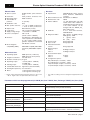
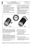
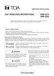
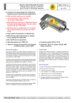
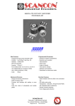
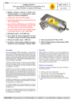
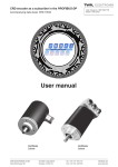
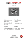
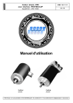
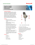
CRD HE Electro-Optical Absolute Encoders Electro-Optical Absolute Encoders CRD 58, 65, 6610534 and 105 Models CRD 58 - CRD 65 - CRD 66 - CRD 105 MULTITURN Interface PROFIBUS-DP 06 / 2013 Compact and robust design for mechanical engineering and industrial plant applications With PROFIBUS-DP interface (process field bus - decentral periphery) DP-slave class 2 functionality in according to Profibus-Profile for Encoders, No. 3.062 Transmission speed: 12 MBaud max. Output code: natural binary Resolution: max. 8192 positions per revolu- tion (13 Bits) Measuring range: max. 4096 revolutions Total number of positions: 225 (25 Bits) Variant “L” with RS 25 round connector Variant “Z” with connecting cap: T-coupler functionality with integrated addressing facility as well as bus-termination resistors Diagnosis LED's for Supply voltage, SRD, Class and Error Protection grade IP 65 or IP 66 Option: flange, housing and connecting cap in stainless steel (model series SRD) CertificateCertificate Z00358Z00359 Construction Variant Z with connecting cap (standard) Flange and housing of aluminium (model series SRD: stainless steel) - shaft of stainless steel 12 mm ball-bearings with Nilos ring seal or radial packing ring seal - code disk of glass or of deformation resistant plastic GaAlAs diodes - photo-transistor array with comparator and trigger circuits for long-term stabilization of the sensor systems gate array - SMD technology. (T-coupler functionality with integrated addressing) General features and modes of connection 1 cable for Bus Out (A', B'), PG 9 cable gland The CRD encoders are designed for connecting directly to PROFIBUS-DP buses as slave stations. The interface is realized with the SPC3 Siemens PROFIBUS controller. The encoders can be operated with transmission speeds of up to 12 MBaud. The protocol is executed in accordance with DP-slave class 2 functionality as laid down in Profibus-Profile for Encoders, No. 3.062 and is described in detail in the user manual TZY 10617. The station address and bus-termination resistors are set Two different modes of electrical connection are provided as standard variants (Line driver in acc. with RS 485): The default address is changed via the service for changing This variant is designed for the following connection cables and provides the following functions: 1 cable for the supply voltage (+ VS = 24 VDC, - VS = 0 VDC), PG 7 cable gland 1 cable for Bus In ( A, B ), PG 9 cable gland with DIP switches in the connecting cap. Variant L with RS 25 round connector: The encoder is connected to the bus with a cable (connec- tor arrangement in accordance with profile description for encoders). the station address of a DP slave, namely DDLM_Set_Slave_Add. The bus-termination resistors have to be installed externally. TWK-ELEKTRONIK GmbH · D-40041 Düsseldorf · PF. 10 50 63 · T. 02 11/63 20 67 · F. 02 11/63 77 05 · e-mail: [email protected] · http://www.twk.de CRD 10534 HE / page 1 Electro-Optical Absolute Encoders CRD 58, 65, 66 and 105 Bus data Electrical data Sensor system: Resolution: Measuring range: GaAlAs diodes, photo-transistor array 8192 positions revolution, max. 4096 revolutions Total number of positions: 225 (25 Bits) Graduation code: Gray Max. position variance: ≤ 2' 38" at 4096 positions/rev. ≤ ±1'59 at 8192 positions/rev. Output code: Natural binary or Gray Code sense: CW or CCW; (programmable) Supply voltage range: + 13,5 VDC to + 30 VDC Power consumption: PD ≤ 3,5 W (Inrush current ≤ 300 mA) Interface: Line driver in acc. with RS 485; galvanic separation is achieved with an opto-coupler. Supply voltage galvanic separation is achieved with DC/DC-converter Electromagnetic compatibility (EMC): EN 61000-4-2 (ESD), EN 610004-4 (Burst), EN 61000-6-4 (Emission) Mechanical data Operating speed: 3000 rpm max. (continuous) 4000 rpm max. (short period) Angular acceleration: 105 rad/s² max. Moment of inertia (rotor):45 gcm² Operating torque: ≤ 5 Ncm (8 Ncm - CRD 66) (at 1000 rpm) Starting torque: ≤ 1 Ncm (4 Ncm - CRD 66) Permissible shaft load: 250 N max. (axial and radial) Bearing life expectancy: 109 revolutions * Mass: ca. 0.5 kg with round connector ca. 0.7 kg with connecting cap * At max. shaft load and working temperature between - 20 °C and + 60 °C. Higher values are permissible with lower loads. Specification: PROFIBUS-DP, Slave stations SPC3 Siemens PROFIBUS controller Data transmission rate: 9.6 kBaud to 12 MBaud Manufacturer code: 1962H Station address: 1 to 126, default value: 123; with variant Z the station address is set with DIP switches; with variant L the station address can be changed with the DDLM_Set_ Slave_Add service GSD File: in acc. with DIN 19245-3, PROFIBUS-DP Diagnosis LEDs*:UBS (green)-VS Supply voltage SRD (green) - SRD C (green)-Class Err (red) -Error Freeze mode: being supported Sync. mode: being supported Automatic baud rate search: being supported Diagnosis bytes Class 2: 63 Diagnosis bytes Class 1: 16 Diagnosis bytes User-Parameter bytes: Class 2: 22 bytes Class 1: 2 bytes Configuration options: D0 (1 Word Input, consistent) - Class1 D1 (2 Word Input, consistent) - Class1 F0 (1 Word Input / Output, consistent) - Class2 F1 (2 Word Input / Output, consistent) - Class2 * True table according connector arrangement supplied with each item. Parameters which can be programmed (via DDLM_Set_Prm / DDLM_Data_Exchange / DDLM_Set_Slave_Add) Value range Description of parameter Code sense CW, CCW Direction of rotation when looking towards the shaft: CW (clockwise), CCW (counter clockwise) Class 2 functionality enable / disable Enable for class 2 functionality Diagnosis routine yes / no Diagnosis routine for the encoder Scaling function enable / disable Enable for programming the parameters Resolution and Total number of positions Resolution: positions per revolution 1 to 8192 positions per revolution Resolution (number of positions per revolution) Total number of positions 1 to 33.554.432 Total number of positions "Reference value (DDLM-Data_Exchange)" 0 to (Total number of positions -1) Value displayed at the reference point Station address 1 to 126 Identification of the station within the bus network (can only be programmed with variant L via RS 25 connector) CRD 10534 HE / page 2 Electro-Optical Absolute Encoders CRD 58, 65, 66 and 105 Environmental data Electrical connections (alternatives) Operating temperature range: optional Storage temperature range: optional Permissible rel. humidity: Resistance to shock: Connecting cap: (variant Z) - 20 °C to + 60 °C - 40 °C to + 85 °C Round connector RS 25: (variant L) - 20 °C to + 70 °C - 40 °C to + 95 °C 85 % without condensation 200 m/s²; 11 ms (DIN IEC 68) Resistance to vibration: 5 Hz to 1000 Hz; 100 m/s² (DIN IEC 68) Protection grade (DIN 40 050) CRD 58 and 65: IP 65 (Nilos ring) CRD 66: IP 66 (radial packing ring) CRD 105: IP65 Connecting cap: IP 00 (when not mounted) Order code format for encoder T-coupler with 3 PG cable glands; integrated addressing facility and bus-termination resistors 12 pin Order code format for connecting cap CRD 58 - 4096 R 4096 C2 Z 01 Z D - P 3 L 4 - 01 Electrical and/or mechanical variants * Electrical and/or mechanical variants * Electrical connection Z = via connecting cap L = with RS 25 round connector Number of LEDs C2 = Device Class 2 (Profile No. 3062) Number of PG unions Max. number of revolutions able to be acquired P = PG union Connecting cap for model CRD Output code R = natural binary G = gray Connecting cap for variant “Z” encoder Model No. 58, 65, 66 or 105 Positions per revolution Model series CRD - absolute encoder with PROFIBUS-DP interface * The basic versions in accordance with the data sheet bear the code number 01. Variations from the basic version are indicated with a consecutive number and are documented in our works. Order code for the stainless steel version: e.g. SRD 66 - 8192 R 4096 C2 Z01 * The basic versions in accordance with the data sheet bear the code number 01. Variations from the basic version are indicated with a consecutive number and are documented in our works. ZD - P3L0 - 11 Notes: Mounting accessories and securing clips can be supplied; see data sheet MZ 10111. The model No. 105 encoders have a 105 mm ø housing and can be supplied on request with a mounting bracket and heating. The TWK user manual TZY 10617 as well as the GSD file and example programmes for the integration of the encoder in a Profibus network with Siemens S7 controlers are available for download on www.twk.de or can be order on CD. Copies of Profibus-Profile for Encoders, No. 3.062 can be obtained from: PROFIBUS Nutzerorganisation e.V., Haid und Neu Str. 7, D-76131 Karlsruhe. CRD 10534 HE / page 3 Electro-Optical Absolute Encoders CRD 58, 65, 66 and 105 Dimensions in mm Variant „Z“ with connecting cap ZD Variant „L“ with RS connector (12 pin) Model No. 58 with synchro-flange Model No. 58 with synchro-flange +0.2 14 -0.5 125 +0.2 ±0.8 14 -0.5 95 4 3 6 97 ±0.8 4 3 6 M4 x 5 +1.5 3x120˚ M4 - 5 +1.5 deep 0˚ 127 42 Model No. 65 with synchro-flange ±0.8 99.5 ±0.8 2 4.5 1.5 +0.1 2.5 -0.5 ø12 h7 M5 x 9 +1.5 3x120˚ 120˚ (3x) M5 - 9 +1.5 deep 38 +0.2 ø12 25 -0.5 Model No. 66 with clamping flange and shaft with flat +0.2 -0.5 ca. 74.5 55 ca. 109 125 10 3.1 6.2 ±0.8 +0.2 30 -0.5 97.5 ±0.8 10 3.1 6.2 M4 x 9 +1.5 3x120˚ ø65 18 ca. 72.5 ca. 107 48 120˚ (3x) M4 - 9 +1.5 deep ca. 57 ø10 f6 9 ø10 f6 ca. 54 38 ø64 ø59 ø36 f8 ø64 -0.1 ø59 -0.1 ø36 f8 18 55 Model No. 66 with clamping flange and shaft with flat 95.5 9 ca. 57 h7 ca. 54 ø65 ø60 ø45 f7 ø65 -0.1 ø60 -0.1 ø45 f7 2 4.5 1.5 +0.1 2.5 -0.5 97.5 ca. 72 42 Model No. 65 with synchro-flange +0.2 25 -0.5 ca. 57 ø6 f7 38 ca. 54 ø6 f7 ca. 107 30 (3 ø65 ø58 ø50 f7 ø65 -0.1 ø58 -0.1 ø50 f7 12 x) 48 Shaft packing seal The mating plugs STR 12 G P07 do not form part of the scope of delivery CRD 10534 HE / page 4 Electro-Optical Absolute Encoders CRD 58, 65, 66 and 105 Design form 105 with heating (option) 20 +0.2 -0.5 31 130 ±0.8 90°(4x) 2.5 ø 12 h7 ø 105 -0.1 ø 70 f7 M6x12 64 Electric heating (optional) Mating connector GGCK105HZG, 4 pin, female 85 Connecting cap ZD-P3L4-01 The cap is listed as a separate item for ordering and delivery. The cap can be separated from the encoder for setting purposes by removing two screws. SUB D connector 15 pin socket Diagnosis LEDs UB SRD C Err Connection terminal 1 (uVs) TWK-ELEKTRONIK DÜSSELDORF DIP-switches ON + UB - OFF Mounting screws M4 (undetachable) Plastic u-silices A B A' B' Connection terminal 2 (Profibus) EMC-gland M12x1.5 EMC-gland M16x1.5 CRD 10534 HE / page 5