1
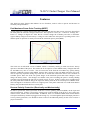
X-90 V3 Solar Charger User Manual
X-90 V3-AUX Solar Charger
User Manual
Issue 3
March 2013
3267 Progress Dr
Orlando, FL 32826
www.apecor.com
Preliminary
1
www.apecor.com
X-90 V3 Solar Charger User Manual
Table of Contents
General Information........................................................................................................................ 3
Introduction................................................................................................................................. 3
Features ....................................................................................................................................... 3
Specification Summary............................................................................................................... 4
Safety .......................................................................................................................................... 4
Solar Panel Selection & Input Power Considerations................................................................. 5
Battery Selection and Typical Operating Temperatures during Charging.................................. 5
Operation......................................................................................................................................... 7
Connections and Configuration ................................................................................................. 7
Charging Procedures................................................................................................................... 9
General Considerations for Maximum Charging and Battery Performance............................... 9
Special Considerations for Charging BB-2590 Li-Ion Batteries ................................................ 9
Special Considerations for Charging BB-590 NiCd Batteries.................................................... 9
Special Considerations for Charging BB-390 NiMH Batteries.................................................. 9
Typical Charging Times ........................................................................................................... 10
Label and LED Status Indicators .............................................................................................. 11
LED Status Information............................................................................................................ 11
Troubleshooting ........................................................................................................................ 12
Maintenance.............................................................................................................................. 12
Features ......................................................................................................................................... 13
Fast Maximum Power Point Tracking (MPPT) ........................................................................ 13
Reverse Polarity Protection (Electrically and Mechanically)................................................... 13
Temperature Protection............................................................................................................. 14
Over Current Protection............................................................................................................ 14
Automatically Dimming LED Indicators.................................................................................. 14
Warranty Statement ...................................................................................................................... 15
Claim Procedure........................................................................................................................ 15
Warranty Exclusions and Limitations....................................................................................... 15
Preliminary
2
www.apecor.com
X-90 V3 Solar Charger User Manual
General Information
Introduction
The X-90 V3 Aux Solar Charger is a portable solar battery charger capable of fast charging a wide array
of typical portable rechargeable batteries, while also providing uninterruptable DC voltage for operating
numerous devices. The charger features numerous advanced and proprietary digital control algorithms,
which enables automatic battery detection, maximum power point tracking (MPPT) of the solar panel,
value-added features and "X-90 Smart Adapters". The charger is able to operate from any solar panel
configuration with Vopen circuit < 60V. The charger directly plugs onto the top of the supported batteries,
and the only wiring needed is the connection to the solar panel or DC source using a polarized SAE plug.
The advanced charge controller minimizes charge time by charging two battery strings simultaneously,
while monitoring critical parameters to ensure safety and reliability. The implementation of high-speed
MPPT delivers maximum charging current, even in low light or poor weather conditions. The simple
LED interface informs the user when the batteries have been completely charged, if there are any fault
conditions, and an estimate of the amount of time remaining until the battery is fully charged or
discharged (depending on operating conditions).
Features
♦ Maximum Power Point Tracking
Up to 30% more power
♦ Universal Charging Algorithm
Identifies chemistry automatically
♦ No User Input Required
♦ Fully Ruggedized Design
♦ Field Replaceable Sense Pins
♦ Fully Protected, including Reverse
Polarity, Over Temperature, Active
Current Limiting, and MIL-810F Compliant
♦ 12V or 24V Solar Panel Input - No
Minimum/Maximum Solar Panel Wattage
♦ Polarized SAE plug to connect to solar panel or source
♦ Available extension input cable for use with other solar panels or DC sources
♦ Available “Y” adapter, to parallel multiple solar panels for maximum charge speed
♦ Compatible with "Smart X-90" adapters, allowing expanded operation with numerous batteries
and adapters
♦ Auto dimming LED indicators reduce the LED
Supported batteries
Chemistry
brightness when there is no input power
BB/UBI-2590/U
Li-Ion
BB-590/U
BB-390B/U
UBBL09
UBBL36
X-90 Smart Adapter
Preliminary
3
NiCd
NiMH
Li-Ion
Li-Ion
Numerous
www.apecor.com
X-90 V3 Solar Charger User Manual
Specification Summary
Maximum Input Voltage *
Minimum Input Voltage
Rated Charge Current
Maximum Ambient Temperature
Converter Efficiency
*
60V
20V
8A (total), 4A per battery string
60°C
96%+
The solar panel’s open circuit voltage VOC must not exceed the maximum input voltage.
Safety
This manual contains important safety and operating instructions for the X-90 Solar Battery Charger.
Read all the instructions and cautions of this manual and on the label of the X-90 before using it. To
reduce the risk of electrical shock, fire, or injury operate charger in only the prescribed manner and use
only with recommended items.
General Safety Guidelines:
•
Observe polarity according to the label when connecting to the input.
•
Do not apply voltages higher than 60V on the input.
•
ONLY connect suggested batteries or X-90 smart adapters to the bottom of the X-90.
•
NEVER apply any other power sources or loads to the bottom connections of the X-90.
•
Only use recommended accessories with the X-90.
•
Only charge recommended batteries; not doing so may result in fire, electrical shock, or
injury.
•
Do not charge a battery if the ambient temperature is outside of the recommended battery
temperature limits.
•
Disconnect the X-90 cables by pulling on the plug, not the cord.
•
Do not use the X-90 with damaged cables or connector pins.
•
Check for proper electrical connections to the cables and battery to avoid excessive heating
and power loss from a loose or dirty connection.
•
Do not try to operate the X-90 if there is any visible damage.
•
Do not operate multiple X-90 units from a single solar source, when using solar power the
panels should be separate for each X-90. It is permissible to use a single DC source, as long
as the power rating is great enough to supply all connected X-90 units.
•
Do not remove the X-90 unit from a charging battery to “check the progress” by looking
at the state of charge indicator of the battery. This will reset the charge algorithm and
increase the charge time. The X-90 unit will inform the user when the battery is fully
charged.
Preliminary
4
www.apecor.com
X-90 V3 Solar Charger User Manual
Solar Panel Selection & Input Power Considerations
Use “12V” or “24V” solar panels or any other panel as long as its maximum power voltage (Vmp) is
greater than 17V and its open circuit voltage (Voc) is below 60V. If available, the X-90 will use up to
~140W to charge a BB-2590 with its maximum rated charge current or ~65W for a BB-390 / BB-590.
The available SAE Y cable can be used to parallel two solar panels in order to increase charge speed.
There is no minimum input power requirement, but charge speed will decrease when used with lower
power solar panels. A list of recommended panels is shown in Table 1 below.
Company
Global Solar Energy, Inc.
Part #
P3 124W 12V
P3 124W 24V
P3 62W 12V
P3 62W 24V
P3 30W 12V
P3 30W 24V
Max. Power @ 25°C
124W
124W
62W
62W
30W
30W
Nominal System Voltage
12V
24V
12V
24V
12V
24V
Table 1: Recommended Solar Panels
Battery Selection and Typical Operating Temperatures during Charging
Table 2 shows a list of BB-XX90 type batteries that can be charged with the X-90. Make sure that each
battery is charged at its allowable ambient temperature range which is typically between 5°C (41°F) and
38°C (100°F). Refer to the label on each battery for exact values.
Please note that the datasheets of most of the batteries list only the operating and storage
temperature ranges which are more extended and not the same as the charging temperature range!
BB-2590 SMBus
BB-2590/U
BB-390A/U or BB-390/U
BB-590/U
BB-2590/U
BB-390B/U
BB-590/U
Charge Current
(per string)
4A
3.2A *
2A
2A
4A
2A
2A
Patco Electronics
Inc.
BB-2590/U
4A
Li-Ion
14.4/28.8
UltraLife Batteries
UBBL02 (UBI-2590)
UBBL10 (UBI-2590 SMBus)
UBBL09 (UBI-2590 12V/24V)
UBBL36 (1/2 UBI-2590)
UBBL13 (UBI-2590 HC)
3.2A *
3.2A *
3.2A *
3.2A *
3.2A *
Li-Ion
Li-Ion
Li-Ion
Li-Ion
Li-Ion
14.4/28.8
14.4/28.8
12V/24V
14.4V
14.4/28.8
Company
Mathews
Associates, Inc.
Bren-Tronics
Part #
Chemistry
Voltage
Li-Ion
Li-Ion
NiMH
NiCd
Li-Ion
NiMH
NiCd
14.4/28.8
14.4/28.8
12.0/24.0
12.0/24.0
14.4/28.8
12.0/24.0
12.0/24.0
Table 2: Recommended Batteries
**Due to design or protection limitations, certain Li-Ion batteries cannot be charge at the full 4A
capability of the X-90 V3. These batteries are detected and charged at a safe 3.2A current level. This
will increase the charge time for the affected batteries.
Preliminary
5
www.apecor.com
X-90 V3 Solar Charger User Manual
Available X-90 Smart Adapters
The X-90 V3 includes the capability to use adapter cables connected to the 6-pin XX90 barrel
connector to allow the charging of numerous other batteries and accessories. The adapters
communicate with the X-90 V3 to indicate the type of adapter connected, so as to allow the X-90
to implement the proper charge algorithm. ApECOR has the capability to provide specific
charging solutions for nearly all battery types, please contact us at [email protected] to request
specific charging capability.
Preliminary
6
www.apecor.com
X-90 V3 Solar Charger User Manual
Operation
Connections and Configuration
There are basically two main methods to power the X-90 for charging the BB-XX90 type batteries: Solar
panels (see Figure 16 and Figure 27) or a DC source such as other batteries (Figure 38 to Figure 510).
The most common setup is with one solar panel connected. To increase charging speed or if clouds are
limiting available power, solar panels can be paralleled. If available, the X-90 will use up to ~140W input
power for BB-2590 batteries or up to ~65W for BB-390 and BB-590 batteries to charge them at their
respective maximum charge currents. Other batteries can be used as power sources as long as they fulfill
the input voltage and power requirements of the X-90. A 24V vehicle bus or two 12V lead-acid batteries
in series could serve as a power source. Furthermore, if there is at least one partially discharged BBXX90 battery available, it could potentially be used to recharge another BB-XX90, so that at least one
battery is fully charged for a mission.
Figure 1: Charger Setup 1 with one Solar Panel as power source
Figure 2: Charger Setup 2 with two Solar Panels in parallel as power source
Preliminary
7
www.apecor.com
X-90 V3 Solar Charger User Manual
Figure 3: Charger Setup 3 with one 24V Battery as power source *
Figure 4: Charger Setup 4 with two 12V batteries in series as power source *
Figure 5: Charger Setup 5 with one BB-x90 Battery as power source *
*
using optional accessories
Preliminary
8
www.apecor.com
X-90 V3 Solar Charger User Manual
Charging Procedures
Connect the X-90 to the power source to be used and the battery to be charged in any order. If the LEDs
on top of the charger are still lit up from a previous charge, wait until all lights are off before connecting
to another battery. Once everything is connected together, the LEDs will blink at different speeds
meaning that the X-90 is analyzing the connected battery for about 2 - 5 seconds to determine its
chemistry. If there was no fault, the “Status LED” will continue to blink, indicating that the battery is
charging. The “85% Charged LED” only lights up when a BB-2590 (Li-Ion) is connected and its capacity
reached about 85% of the total capacity. The charge is finished once the “Status" LED is on. Then the
battery and/or power source can be disconnected or another battery can be charged.
General Considerations for Maximum Charging and Battery Performance
Align solar panel perpendicular to the sun and avoid shading of the panel whenever possible for
maximum power. Place the X-90 with the battery in the shade wherever possible, especially at high
ambient temperatures. Even though the X-90 won’t be damaged when exposed to full sun while
charging, the battery has lower maximum temperature limits while being charged that are typically
around 38°C (100°F). One simple method of shading the X-90 while charging is to place it underneath a
rucksack.
Special Considerations for Charging BB-2590 Li-Ion Batteries
Besides the “Status LED” there is also a “85% Charged LED” for BB-2590 batteries. It will come on
once approximately 85% of the battery’s full capacity is reached. To charge the last 15% it will take
about 30 to 40% of the total charge time! If there are more batteries to be charged, it makes sense to take
off the current battery and to charge another fully depleted BB-2590 which could be charged to ~50% in
the same time. This allows the user to have a higher overall state of charge for all the batteries instead of
only having one battery completely charged.
Special Considerations for Charging BB-590 NiCd Batteries
The BB-590 battery is the hardest to accurately be charged to its full capacity using a variable power
source such as a solar panel. In order to use the full potential of the charge algorithm implemented in the
X-90, the following things have to be considered:
•
Don’t charge a battery if it is already known to be full. In some conditions a fully-charged
battery might overheat if charged again. If possible, record the date of the last full charge of the
battery and use it before recharging again.
•
If possible, discharge the two battery strings inside the BB-590 equally. Don’t repeatedly unplug
the X-90 and connect it back to the battery. Those conditions might confuse the X-90 and it
might terminate the charge too early.
Special Considerations for Charging BB-390 NiMH Batteries
The BB-390 has an internal temperature sensor which allows the X-90 to charge the battery more
accurately and protect it from over-charge. Prior to charging, the battery should be kept in a cool place
because the charge cannot be started if its temperature is already above 40°C (104°F) in order to protect
the battery from over-temperature. Therefore it is also not recommended to repeatedly unplug the X-90
from the battery and put it back on only to see the state-of-charge display. This is because once the
battery’s temperature during charge is above 40°C (104°F) the X-90 will not start charging the battery
again unless its temperature has dropped below that point.
Preliminary
9
www.apecor.com
X-90 V3 Solar Charger User Manual
Typical Charging Times
Battery
Chemistry
Capacity
(Ah)
Max Charge
Current
BB-2590
Li-Ion
14.4
4A/String(1)
BB-390
BB-590
NiMH
NiCd
9.8
4.8
2A/String
2A/String
UBBL09
Li-Ion
18.4
4A/String
UBBL36
Li-Ion
8.7
4A
Solar Panel
(Watts)
62
124
DC Source
62
62
62
124
DC Source
62
Typical Full Charge
Time (Hours)
4.5 (3 hrs 85%)
2.65 (1.75 hrs 85%)
2.5 (1.5 hrs 85%)
3
1.5
5.25
3.25
3
2.75 (2 hrs 85%)
Table 3: Typical Charging Times
Notes:
(1)
Only applies when charging certain BB-2590 type batteries. Depending on the design limitations imposed by
various manufacturers, the X-90 will automatically charge some BB-2590 type batteries at 3.2A per string.
Preliminary
10
www.apecor.com
X-90 V3 Solar Charger User Manual
Label and LED Status Indicators
LED Status Information
Fault
Status
85%
Charged
Red
Green
Green
Off
Off
Off
Off
Off
Blinking
(2)
Off
On
On/
Blinking
-
Meaning
Action to take
Ready to connect
Charging
Connect battery
Optional: Disconnect battery and
connect a lower charged battery. In
Charging, battery is
On (1)
the time it takes to charge the last
(1)
85% full
15%, the first 50% of an empty
battery could be charged. (1)
On
Finished charging
Disconnect battery
Check connections, make sure that
Fault, converter not
operation of converter is within the
running
maximum ratings
Table 4: LED status information
Notes:
(1)
Only applies when charging Li-Ion
(2)
Blinking speed changes based on charging current: ~ (0.5 to 20) blinks/sec for a total charge current of (0 to 8) A
Preliminary
11
www.apecor.com
X-90 V3 Solar Charger User Manual
Troubleshooting
Condition
Fault light blinking for a
long period of time
Possible Causes
Input power may be low
Solutions
Wait for more sunshine
Orient panel perpendicular to sun
Table 5: General Trouble Shooting
Condition
X-90 finishes charge but
state-of-charge display
doesn’t show all 5 bars
85% light turning on and
off
Possible Causes
The X-90 might have stopped early
because of changing input power
Internal battery SOC meter not accurate
Solutions
Unplug X-90 from the battery and plug
back onto it to top off battery
A full discharge and charge cycle of the
battery might recalibrate the gauges
Available power changes a lot while
This is normal, no action needs to be
battery is approximately 85% done
taken
Table 6: Trouble Shooting for BB-2590 (Li-Ion)
Condition
There is no power
available from battery
after finished charging
Possible Causes
Battery was charged at higher
temperatures than recommended which
triggered an internal safety switch
Condition
X-90 finishes charge but
state-of-charge display
doesn’t show all 5 bars
Possible Causes
Solutions
The battery hasn’t been discharged
Discharge battery completely before
completely for a longer period of time
charging again
which causes offsets
Find a cool and ventilated place to charge
Battery temperature got too high
the battery
because of ambient temperature being
(Battery temperature needs to be below
above 38°C (100°F), therefore charge
40°C (104°F) for the X-90 to start
was terminated early to protect the
charging again)
battery
Temperature of battery is above 40°C
Let battery cool down, X-90 will start
(104°F)
charging battery once temperature is good
Table 8: Trouble Shooting for BB-390 (NiMH)
Fault light blinking
Solutions
Let battery cool down, after it cools power
will be available again.
Make sure that battery is not being
charged beyond recommended charging
temperatures.
Table 7: Trouble Shooting for BB-590 (NiCd)
Maintenance
The X-90 has no user serviceable parts except for the spring sense pins. Check for broken, corroded, or
otherwise damaged cable or battery contacts. Make sure that all battery contacts are straight and that the
three spring pins can be pushed in and come out again if released. If a defect has been found, discontinue
use of the X-90 and contact ApECOR. The input cable may be repaired if necessary; however do NOT
attempt to repair battery contacts. Make sure that all contacts are free of mud, dirt, dust, oil and grease. If
found dirty, they can be cleaned with a damp non-abrasive cloth and allowed to air dry or wiped with a
clean dry non-abrasive cloth. In case of oils and grease, use a mild soap/water solution on a cloth to clean
the contacts, then rinse the contacts with water.
If a spring sense pin is damaged, contact ApECOR to purchase a spring pin replacement kit. This can
allow the user to make the repair without returning the X-90 unit.
Preliminary
12
www.apecor.com
X-90 V3 Solar Charger User Manual
Features
The X-90 has many features that enhance its core functions, make it safer to operate and increase its
reliability and performance.
Fast Maximum Power Point Tracking (MPPT)
A solar panel has a unique characteristic that is derived from the fact that as more current is drawn from
the solar panel the more the voltage will decrease. The respective curves (IV – Current vs. Voltage, PV –
Power vs. Voltage) in Figure 611 show that at a certain voltage the available power has a maximum.
Typical battery chargers use the battery’s voltage to select where the solar panel is operating on the curve
and this point of operation is mostly lower than the maximum power point (MPP).
Figure 6: IV and PV curves for a typical solar panel
The X-90 uses an advanced version of MPPT which is constantly running to make sure that it always
operates at the MPP of the panel. This makes the X-90 superior to other MPPT battery chargers that look
for the MPP every once in a while. This is because the X-90 finds the new MPP very quickly during
changing conditions whereas other MPPT chargers don’t operate at the new MPP until their next scan.
This is especially important during days with lots of clouds and wind which lead to fast variations in
available power. Since the X-90 can operate longer at the maximum power than other chargers, it can
charge the battery faster. The changes in available solar power reaching the panel is usually shading
caused by objects blocking the sun such as clouds, people, or trees. If there is more power available from
the solar panel than needed to charge the respective battery, then the X-90 will drop out of MPPT mode.
This can happen for all batteries if there is a higher power solar panel connected or it could mean that the
battery (only for BB-2590 batteries) is nearly full.
Reverse Polarity Protection (Electrically and Mechanically)
In order to protect the entire system the X-90 has a reverse polarity protection (RPP) on the input and
output connections. If there is no positive voltage seen on the terminals of the X-90, it won’t allow any
current to flow, which is the electrical RPP. In addition, there is a mechanical RPP which means that the
solar panel and battery cannot be plugged in the wrong way. Even though the input and output ports have
reverse polarity protection, care should be taken to observe the indicated polarity on the wires to assure a
proper connection.
Preliminary
13
www.apecor.com
X-90 V3 Solar Charger User Manual
Temperature Protection
The X-90 provides the full charge current up to a certain internal temperature. Above that temperature it
will linearly de-rate the charge current up to a maximum allowable internal temperature in order to protect
its circuitry to safe limits. The auxiliary output circuit also features temperature protection independent of
the battery charging protection functions. If the auxiliary output is overloaded, and the temperature
protection trips, the battery will still continue to charge. After the temperature has fallen to an acceptable
level, the functionality will resume.
Over Current Protection
The X-90 is protected against over-current and short circuit conditions. Normally, it will limit the
maximum charge current to 4A for a BB-2590 battery or to 2A for a BB-390 / BB-590 battery. If under
some condition the current exceeds that value a fault may be triggered. After a fault, the software of the
X-90 can successfully reset the fault in case it was only a temporary condition. If in the case of a failure
where the high current could not be stopped because the circuitry of the X-90 is damaged, an internal fuse
will break and disconnect from the battery. In that case the X-90 would be permanently non-operational.
This behavior is preferred, as the battery is protected from short circuit currents that could have led to a
catastrophic failure of the battery.
Automatically Dimming LED Indicators
The X-90 will automatically reduce the brightness of the LED indicators to approximately 30% of the
maximum brightness when there is no incoming power. When charging from a solar source, the LEDs
are at full brightness, so as to be visible in the sun. In other cases the X-90 will save power by reducing
the LED brightness, which can also serve to reduce excess light emission in dark environments. NOTE:
In tactical environments, the soldier worn X-90 should be securely strapped into a pouch which will
completely cover the indicator LEDs.
Preliminary
14
www.apecor.com
X-90 V3 Solar Charger User Manual
Warranty Statement
The X-90 Solar Charger is warranted to be free from defects in material and workmanship for a period of
TWO (2) years from the date of shipment to the original end user. ApECOR will, at its option, repair or
replace any such defective products.
Claim Procedure
•
•
•
Before requesting warranty service, check the User Manual to be certain that there is a problem
with the controller. Contact ApECOR to request Returned Material Authorization (RMA). Return
the defective product to your authorized ApECOR distributor with shipping charges prepaid.
Provide proof of date and place of purchase.
To obtain service under this warranty, the returned products must include the model, serial
number and detailed reason for the failure, the module type, solar panel size, type of batteries.
This information is critical to a rapid disposition of your warranty claim.
ApECOR will pay the return shipping charges if the repairs are covered by the warranty.
Warranty Exclusions and Limitations
This warranty does not apply under the following conditions:
• Damage by accident, negligence, abuse or improper use.
• PV or load currents exceeding the ratings of the product.
• Unauthorized product modification or attempted repair.
• Damage occurring during shipment.
THE WARRANTY AND REMEDIES SET FORTH ABOVE ARE EXCLUSIVE AND IN LIEU OF
ALL OTHERS, EXPRESS OR IMPLIED. APECOR SPECIFICALLY DISCLAIMS ANY AND ALL
IMPLIED WARRANTIES, INCLUDING, WITHOUT LIMITATION, WARRANTIES OF
MERCHANTABILITY AND FITNESS FOR A PARTICULAR PURPOSE.
No ApECOR distributor, agent or employee is authorized to make any modification or extension to this
warranty.
APECOR IS NOT RESPONSIBLE FOR INCIDENTAL OR CONSEQUENTIAL DAMAGES OF ANY
KIND, INCLUDING BUT NOT LIMITED TO LOST PROFITS, DOWNTIME, GOODWILL OR
DAMAGE TO EQUIPMENT OR PROPERTY.
3267 Progress Dr.
Orlando, FL 32826
Email: [email protected]
Website: www.apecor.com
Preliminary
15
www.apecor.com