1
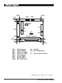
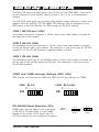
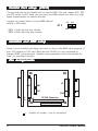
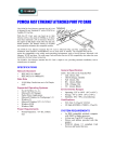
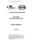
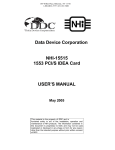
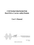
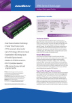
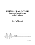
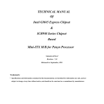
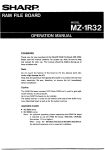
PIA-3410 High-speed Multi I/O Module Description The PIA-3410 is a high-speed Multi I/O module. It comes with two serial ports (RS-232 x 1, RS-232/485 x 1), one bidirectional printer port that supports SPP, ECP and EPP modes, an IDE HDD interface and a floppy disk controller. The PIA-3410's industrial grade reliability lets it operate continuously at temperatures up to 60ºC. The PIA-3410 can be setup using normal jumper settings or ,when used together with the PIA-3310 PC/104 386SX CPU Module, can be 100% configured in the BIOS setup Chipset : SMC FDC37C665GT I/O configuration : by jumpers or in BIOS (of PIA-3310) Bus interface: PC/104 IDE HDD interface : supports up to two IDE (AT bus) hard disk drives. FDD interface : supports up to two FDD, 5¼" (360 KB and 1.2 MB) and / or 3½" (720 KB and 1.44 MB) Enhanced bidirectional parallel port : supports EPP/ECP/SPP Serial ports : one RS-232 and one RS232/485 port, jumper selectable. Both channels with 16C550 compatible UARTs with 16-byte FIFO for speeds up to 115.2 Kbps Part number : ARB50034101000 Power requirements: Single 5V @ 320 mA Physical and Environmental Dimensions : 95 x 90 mm Weight : 100 gram Operating temperature: 0 ~ +60°C Storage temperature : -25 ~ +80°C Relative humidity: 0 ~ 90% non-condensing Boar d La yout Board Lay 0.350 CN5 3.775 3.250 CN6 3.575 JP1 CN10 P1 CN1 CN7 CN2 JP2 CN8 PC/104 Connector CN9 0.200 0 0.200 0 CN1 : CN2 : CN5 : CN6 : CN7 : CN8 : CN9 : CN10 : FDD connector RS-232 COM2 IRQ select COM1 IRQ select COM2 IDE connector RS-232 COM1 RS-485 COM2 ECP, DMA select 3.350 3.550 JP1 : IDE LED JP2 : RS-232/485 select P1 : Parallel port connector (dimensions in inches, not to scale) 2 PIA-3410 User's Manual Serial P or Por ortt setup (CN 5/6/8/9 and JP2) The PIA-3410 offers two serial ports: one RS-232 and one RS232/485. These ports let you connect to serial devices (mouse, printers, etc.), or to a communication network. The PIA-3410 serial ports can be setup using normal jumper settings or, when used together with the PIA-3310 PC/104 386SX CPU Module, can be configured in the BIOS setup of the CPU Module. For BIOS setup see PIA-3310 manual. COM 1 RS-232 port (CN8) The primary serial port connector, a 10-pin, dual-in-line, male header is located on the right side of the module. COM 2 RS-232 (CN2) The secondary serial port connector, a 10-pin, dual-in-line, male header is located on the left bottom side of the module. The connector is only to be used for RS-232 operation. For the RS-485 function a separate header is placed. COM 2 RS-485 (CN9) The secondary serial port for the RS-485 option, a 2-pin, male header is located on the left side of the module below the IDE port. The connector is only to be used for RS-485 operation. COM1 and COM2 Interrupt Settings (CN5, CN6) CN5 controls the interrupt for COM1 and CN6 controls the interrupt for COM2 CN5 IRQ 3 4 5 6 7 9 COM2 RS-232/485 IRQ 3 4 5 6 7 9 COM1 RS-232 CN6 RS-232/485 Mode Selection (JP2) COM2 offers you the option to be used either in RS-232 or RS-485 mode. A 3-pin header located on the center of the board near the PC/104 connector let you configure this option. PIA-3410 User's Manual 1 2 3 1 2 3 RS-232 mode RS-485 mode JP 2 3 Parallel P or Por ortt setup (CN10) The port interrupt for the parallel port is fixed at IRQ5. The port support SPP, EPP and ECP mode. In ECP mode you can select the DMA channel you wish your high speed communication to traverse through. Jumpers on jumper block 2 control DMA channel setting in ECP mode. ECP ECP JP 2 DMA1 DMA 2 - DMA 1 (both left two pins closed) - DMA 2 (both right two pins closed) Har ddisk and FDD setup Hard Setup of your harddisk and floppy disk drive is done in the BIOS setup program of your CPU module or CPU card. Note that the PIA-3410 is only supported by standard BIOS (not enhanced). Harddisk setup parameters have to be entered by hand, no auto-detect function. Pin Assignments CN7 P1 CN1 CN2 DD+ = 4 CN9 CN8 PC/104 Connector Position of number 1 pin on connectors PIA-3410 User's Manual Parallel Printer Connector (P1) Pin 1 2 3 4 5 6 7 8 9 10 11 12 13 Name Strobe# D0 D1 D2 D3 D4 D5 D6 D7 Acknowledge Busy Paper Empty Printer Select Pin 14 15 16 17 18 19 20 21 22 23 24 25 26 Name Auto Form Feed Error# Initialize Printer Select In GND GND GND GND GND GND GND GND NC RS-232 Serial Port COM1 (CN8) Pin 1 2 3 4 5 6 7 8 9 Name Data Carrier Detect (DCD) Receive Data (RxD) Transmit Data (TxD Data Terminal Ready (DTR) Ground (GND) Data Set Ready (DSR) Request To Send (RTS) Clear To Send (CTS) Ring Indicator (RI) RS-232 Serial P or Por ortt COM2 (CN2) Pin 1 2 3 4 5 6 7 8 9 Name Data Carrier Detect (DCD) Receive Data (RxD) Transmit Data (TxD Data Terminal Ready (DTR) Ground (GND) Data Set Ready (DSR) Request To Send (RTS) Clear To Send (CTS) Ring Indicator (RI) PIA-3410 User's Manual 5 RS-485 Serial P or Por ortt COM2 (CN9) Pin 1 2 Name Data + Data - HDD LED (JP1) Pin 1 2 Name + - IDE Har d Drive Connector (CN1) Hard Pin 1 3 5 7 9 11 13 15 17 19 21 23 25 27 29 31 33 35 37 39 6 Name -RESET IDED7 HD6 HD5 HD4 HD3 HD2 HD1 HD0 GND NC -IOW -IOR IORDY NC IRQ14 IDEA1 IDEA0 -HDCS0 HDDLED Pin 2 4 6 8 10 12 14 16 18 20 22 24 26 28 30 32 34 36 38 40 Name GND HD8 HD9 HD10 HD11 HD12 HD13 HD14 HD15 NC GND GND GND IDEALE GND -IOCS16 NC IDEA2 -HDCS1 GND PIA-3410 User's Manual 3.2 Pin 1 3 5 7 9 11 13 15 17 19 21 23 25 27 29 31 33 Floppy Drive Connector (CN2) Name Pin GND 2 GND 4 GND 6 GND 8 GND 10 GND 12 GND 14 GND 16 GND 18 GND 20 GND 22 GND 24 GND 26 GND 28 GND, DRATE1/MEDIA_ID1 30 GND 32 GND, MEDIA_ID0 34 PIA-3410 User's Manual Name RM/LC NC NC, DRATE0 -INDEX -MTR0 -DRV1 -DRV0 -MTR1 DIR -STEP -WD -WG -TRK0 -WP -RDATA HDSEL DSKCHG 7 Warranty This product is warranted to be in good working order for a period of one year from the date of purchase. Should this product fail to be in good working order at any time during this period, we will, at our option, replace or repair it at no additional charge except as set forth in the following terms. This warranty does not apply to products damaged by misuse, modifications, accident or disaster. Vendor assumes no liability for any damages, lost profits, lost savings or any other incidental or consequential damage resulting from the use, misuse of, or inability to use this product. Vendor will not be liable for any claim made by any other related party. Return authorization must be obtained from the vendor before returned merchandise will be accepted. Authorization can be obtained by calling or faxing the vendor and requesting a Return Merchandise Authorization (RMA) number. Returned goods should always be accompanied by a clear problem description. 8 PIA-3410 User's Manual