1
SERVICE MANUAL EPC-3221 &RPSDFW3&, SCB (C1000BX-SVE) and C1XTN02 Transition I/O Module P/N 007-01143-0000 October 2000 A system controller board (SCB) is also known as a single-board computer. © 2000 RadiSys Corporation All Rights Reserved Published in USA EPC-3221 CompactPCI® System Controller Board and Optional C1XTN02 Transition I/O Module Limited Warranty A. RadiSys Corporation warrants that the item sold by it hereunder will be free from defects in materials or workmanship, under normal use and service, for a period of 2 years from date of shipment. Said item will meet the specifications in effect at the time of manufacture. RadiSys' sole obligation under this warranty shall be, at its option, to repair or replace, without charge, any defective component of said item, within a reasonable period of time. B. RadiSys Corporation shall not be liable under this warranty for (i) the item that the Buyer alleges to be defective and was repaired or altered by someone other than RadiSys designated personnel or authorized representative, unless such repair or alteration was effected pursuant to prior written approval of RadiSys, or (ii) where the Buyer fails to notify RadiSys of any alleged defect within the period of warranty, or (iii) where the Buyer fails to return the allegedly defective item to RadiSys Corporation, in Houston, Texas, USA, freight prepaid, or (iv) where the item was altered or damaged in a way which RadiSys reasonably determines to affect the performance and reliability of the item, or (v) where the item was subject to misuse, neglect, or accident. The rights and remedies granted to the Buyer under this paragraph constitute the Buyer's sole and exclusive remedy against RadiSys Corporation, its officers, agents, and employees, for negligence, inexcusable delay, breach of warranty, express or implied, or any other default relating to the item or RadiSys’ duties to eliminate any errors. This warranty supersedes any other warranty, whether expressed, implied, or statutory, including but not limited to any warranty for fitness of purpose, merchantability, or freedom from infringement or the like, and any warranty otherwise arising out of any proposal, specifications, or sample. Furthermore, RadiSys Corporation neither assumes nor authorizes any person to assume for it any other liability. The software included with this equipment is warranted only in accordance with the terms of its license agreement. Except as warranted in that license agreement, the manufacturer of the software disclaims all warranties and conditions with regard to the software, including all implied warranties and conditions of merchantability, fitness for a particular purpose, title, and non-infringement. Every effort has been made to ensure that the information provided in this manual is complete and accurate. However, technical inaccuracies or typographical errors may be inadvertently included. RadiSys assumes no responsibility for any errors that may be contained in this document. RadiSys makes no promise to update or keep current the information contained in this document. Information in this document, including product specifications, is subject to change without notice. All tradenames referenced are the service mark, trademark, or registered trademark of the respective manufacturer. ii Service Manual Important Always use caution when handling or operating the equipment. Only qualified and trained electronics service personnel should access the equipment. Use extreme caution when installing or removing components. For additional information, please contact RadiSys Technical Support at 1–800–438–4769 or 1–713–541–8200 Monday through Friday between 7:00 a.m. and 6:00 p.m., Central Time, continental USA. Wichtig Arbeiten am System bzw. Betrieb des Systems, sollten immer mit der nötigen Vorsicht vorgenommen werden. Nur qualifiziertes und ausgebildetes Fachpersonal sollte am Inneren des Gerätes arbeiten. Beim Installieren und Entfernen von Komponenten ist besondere Vorsicht geboten. Für weitere Informationen wenden Sie sich bitte an den Technical Support von RadiSys: • USA: 1–800–438–4769 oder 1–713–541–8200 Montags bis Freitags von 0700 Uhr bis 1800 Uhr, Central USA. • International: +31–36–5365595 Montags bis Freitags von 0830 Uhr bis 1700 Uhr. (CET GMT +1.00) Changes or modifications not expressly approved by RadiSys Corporation could void the product warranty and the user’s authority to operate the equipment. Service Manual iii EPC-3221 CompactPCI® System Controller Board and Optional C1XTN02 Transition I/O Module Notice This equipment has been tested and found to comply with the limits for a Class A digital device, pursuant to Part 15 of the FCC Rules. These limits are designed to provide reasonable protection against harmful interference when the equipment is operated in a commercial environment. This equipment generates, uses, and can emit radio frequency energy and, if not installed and used in accordance with this instruction manual, may cause harmful interference to radio communications. Operation of this equipment in a residential area is likely to cause harmful interference, in which case, the user will be required to correct the interference at the user's expense. This device complies with Part 15 of the FCC Rules. Operation is subject to the following conditions: • This device may not cause harmful interference • This device must accept any interference received, including interference that may cause undesired operation Any change or modification not expressly approved by the manufacturer is prohibited and could void the user's authority to operate the equipment. This product also meets requirements for compliance with EN55022, Class B ITE. iv Service Manual Symbols Notice: This symbol indicates an item for special consideration. Warning: This symbol indicates the presence of a potential hazard that can cause personal injury. Only qualified and trained electronics service personnel should access the equipment. Service Manual v EPC-3221 CompactPCI® System Controller Board and Optional C1XTN02 Transition I/O Module Customer Support Accessing the Web Site In-depth printable service manuals and other documentation are available for download from the RadiSys Web site: http://www.radisys.com Then click on Support to access a link to the manuals, addenda, drivers and BIOS. The documentation for current and discontinued products is available at this Web site in Adobe® Acrobat® PDF format. Documentation may be viewed and printed using the free Acrobat® Reader™ software. Calling Technical Support 1. Have the RadiSys product model and serial number available. 2. Call Technical Support: In the continental USA, Monday – Friday, 7:00 a.m. – 6:00 p.m., Central Time, dial • 1–800–438–4769. Outside the USA, dial 1–713–541–8200 (add long distance/international access • codes). In Europe, Monday – Friday, 8:30 a.m. – 5:00 p.m., dial +31–36–5365595. • Inspection of Contents / Packaging of Product The packaging for this product has been tested to assure that it will withstand responsible handling by the carrier. Caution: Inspect contents immediately and file a claim with the delivering carrier for any damage. Save the shipping box and packaging material to use for any further shipment of this equipment. However, if the packaging is damaged and is not suitable for shipment, call RadiSys Technical Support to obtain new packaging. The warranty may be void if the product is returned using unapproved or damaged original packaging. Returning Your Product The Returned Material Authorization (RMA) number and the serial number of each returned product must be written on the outside of the package and on any enclosed correspondence. Note: The factory will refuse the shipment if it is sent freight collect or if it does not display an RMA number. vi Service Manual Table of Contents Chapter 1 Introduction 1 EPC-3221 System Controller Board ......................................................................................2 C1XTN02 Rear Transition I/O Module..................................................................................6 Chapter 2 6 Steps to Operation 9 Handling the EPC-3221 and C1XTN02 ...............................................................................10 Step 1: Check Switch Settings..............................................................................................12 Step 2: Install the SCB .........................................................................................................14 Step 3: Install the C1XTN02 Transition I/O Module ...........................................................16 Step 4: Attach Peripheral Devices ........................................................................................18 Step 5: Power-On the System...............................................................................................20 Step 6: Run the Setup Utility................................................................................................21 Chapter 3 Technical Data 27 Specifications .......................................................................................................................28 Pin Signals ............................................................................................................................30 Peripheral Connections.........................................................................................................33 CompactPCI® Connectors ....................................................................................................34 Console Redirection .............................................................................................................38 Platform Management ..........................................................................................................39 Watchdog Timer ...................................................................................................................43 Installing Memory ................................................................................................................44 System Battery Replacement................................................................................................46 Product Identification ...........................................................................................................48 Service Manual vii EPC-3221 CompactPCI® System Controller Board and Optional C1XTN02 Transition I/O Module List of Figures Figure 1. Figure 2. Figure 3. Figure 4. Figure 5. Figure 6. Figure 7. Figure 8. Figure 9. Figure 10. Figure 11. Figure 12. Figure 13. Figure 14. Figure 15. Figure 16. Figure 17. viii EPC-3221 Components ...................................................................................... 4 Front I/O Panel Components .............................................................................. 5 Rear Transition I/O Module Components .......................................................... 7 Safely Handling the Components..................................................................... 11 Switch Block Location ..................................................................................... 13 Installing the SCB ............................................................................................ 15 Installing the Transition I/O Module ................................................................ 17 Peripheral Connectors ...................................................................................... 19 Setup Utility Main Menu.................................................................................. 20 Parallel Port Cable............................................................................................ 32 USB Port Cable ................................................................................................ 32 CompactPCI® Connectors ................................................................................ 36 SCB Platform Management.............................................................................. 39 Memory Sockets............................................................................................... 45 Installing Memory Modules ............................................................................. 45 System Battery Components ............................................................................ 47 Battery Installation ........................................................................................... 47 Service Manual List of Tables Table 1. Table 2. Service Manual EPC-3221 SCB Sensors....................................................................................... 41 Sensor Threshold Descriptions ............................................................................ 42 ix EPC-3221 CompactPCI® System Controller Board and Optional C1XTN02 Transition I/O Module Notes x Service Manual Introduction Chapter 1 This chapter discusses functions and features of the equipment that can be accessed only by qualified and trained electronics service personnel. The material contained in this chapter does not discuss any user-accessible parts or operations. All tasks related to material in this chapter must be referred to qualified service personnel. This chapter discusses the primary features of the EPC-3221 System Controller Board (SCB) and the optional C1XTN02 Rear Transition I/O Module (XIO). If you are familiar with the primary features and components of the EPC-3221 and the C1XTN02 Transition I/O Module, and you wish to quickly begin operating the equipment, go to Chapter 2, “6 Steps to Operation” on page 9 and return to this chapter later at your convenience. Service Manual 1 EPC-3221 CompactPCI® System Controller Board and Optional C1XTN02 Transition I/O Module EPC-3221 System Controller Board Standard Features The RadiSys EPC-3221 System Controller Board provides the following standard features (Figure 1 on page 4 and Figure 2 on page 5): • Intel® Celeron™ Processor in the PPGA package (370-pin socket: PGA370) 300, 366, 433 MHz, and higher as technology becomes available • 128 KB integrated Level 2 write-back cache operating at full clock speed • • Intel 440BX AGPset 82443BX Host Bridge/Controller (System Controller, or North-Bridge) • 82371EB PCI-to-ISA/IDE Xcelerator (PIIX4E, or South-Bridge) • • SMSC Super I/O Controller • Programmable logic device (for on-board logic) • Two 168-pin DIMM sockets for up to 512 MB PC100 +3.3 V unbuffered SDRAM (or higher as technology becomes available) • 4 Mb (512 KB x 8) boot block flash memory device • Hitachi H8/3437 system monitoring microcontroller with I2C bus interface • Ultra SCSI • AGP video • 10/100BaseT Ethernet • Intel 21150 PCI-to-PCI Bridge • Remote/Local Temperature Sensor with SMBus serial interface • 230 kbps ESD-protected RS-232 serial port • MicroMonitor • Clock synthesizer and SDRAM clock buffer • CR2032 lithium (Li/MnO2) coin battery to retain date, time, and CMOS parameters • Four-position switch block for elements of system configuration • System management bus 4-pin male shrouded, keyed header on the board surface • System management power 2-pin male header on the board surface • Two serial port 9-pin male D-Sub connectors on the front I/O panel (RS-232) • Parallel port 25-pin female D-Sub connector on the front I/O panel (AT-compatible / bi-directional / enhanced operations) • USB Series A male connector on the front I/O panel • PS/2 keyboard and mouse 6-pin female mini-DIN connectors on the front I/O panel • System Power and IDE / SCSI activity LEDs on the I/O panel 2 Service Manual Chapter 1: Introduction Optional Features The EPC-3221 is available with the following optional on-board peripherals: • C1XTN02 Rear Transition I/O Module • PCI Bridge Card SCSI The SCSI option provides the following features and components: Note: The EPC-3221 supports only single-ended (SE) SCSI devices. • • Adaptec AIC®-7890 PCI-to-Ultra SCSI Controller Active SCSI terminators Video The AGP Video option provides the following features and components: • CHIPS 69000 HiQVideo™ Accelerator with 2 MB integrated SDRAM • VGA video 15-pin female D-Sub connector on the I/O bracket Ethernet The Ethernet option provides the following features and components: • Intel 82559 10/100 Mb/sec Ethernet LAN Controller • RJ-45 10/100BaseT Ethernet connector on the I/O panel • Ethernet activity LEDs on the I/O panel Rear Transition I/O The C1XTN02 Rear Transition I/O Module is also an optional component to expand connectivity and functionality of the EPC-3221 SCB, for use as part of a cPCI computer system. See C1XTN02 Rear Transition I/O Module on page 6. PCI Bridge Card To drive an additional PCI bus and increase the number of PCI devices, the EPC-3221 can be equipped with the optional CPBRI01 PCI-to-PCI Bridge Card. Note: The EPC-3221 and the PCI Bridge Card each use the Intel 21150 PCI-to-PCI Bridge and identical CompactPCI connectors for J1 and J2. Service Manual 3 EPC-3221 CompactPCI® System Controller Board and Optional C1XTN02 Transition I/O Module Figure 1. EPC-3221 Components Upper Injector/Ejector Lever (shown closed/locked) Hitachi Altera Max 4 MB Flash Speaker System DIMM H8/3437 Reset Sockets EMP7128S Memory Device Microcontroller Header (2) Micro- PLD Monitor Guide Pins J5 CompactPCI Connector System Reset Button MAX 3185 Serial Port (2 places) RJ-45 Ethernet Connector SDRAM Clock Buffer Super I/O Controller DIP Switch Block J4 CompactPCI Connector Serial Port 1/2 Connectors Intel 82559 Ethernet Controller HiQVideo Adapter Intel 82371EB PCI-ISA/IDE Xcelerator (PIIX4E) Parallel Port/ VGA Connectors System Battery Intel 82443BX System Controller with Heatsink PS/2 Mouse/Keyboard Connectors Clock Synthesizer SCSI Terminators (2 places) SCSI Controller USB0 Connector J2 CompactPCI Connector J1 CompactPCI Connector Intel 21150 PCI-to-PCI Bridge Lower Injector/Ejector Lever (shown open/unlocked) Guide Pins Temperature Sensor PCI Bridge Card Connector Celeron Processor with Heatsink Installed Intel Celeron Processor 370-pin Socket (PGA370) 4 Service Manual Chapter 1: Introduction Figure 2. Front I/O Panel Components Injector / Ejector Lever Ethernet Activity LED RJ-45 Ethernet Connector Captive Fastener (2 places) System Reset Button Ethernet Link Integrity LED Serial Port 2 Connector Serial Port 1 Connector VGA Connector Parallel Port Connector PS/2 Keyboard Connector PS/2 Mouse Connector System Power LED IDE / SCSI Activity LED USB0 Injector / Ejector Lever Captive Fastener (2 places) Service Manual 5 EPC-3221 CompactPCI® System Controller Board and Optional C1XTN02 Transition I/O Module C1XTN02 Rear Transition I/O Module Standard Features The optional C1XTN02 provides the following features (Figure 3): • SCSI 68-pin (Ultra Fast/Wide) Micro-D female connector • SCSI 50-pin (Ultra Fast/Narrow) shrouded, latching header • Floppy drive 34-pin shrouded, latching header • Two EIDE or IDE device 40-pin shrouded, latching headers • Speaker header • System reset header • System Monitor header that can be used to interface with alarm components • Parallel port 26-pin shrouded, latching header Note: A cable attaches this header to the parallel port connector on the rear I/O panel. See Figure 10 on page 32. • USB1 header Note: A cable attaches this header to the USB1 connector on the rear I/O panel. See Figure 11 on page 32. Rear I/O Panel The C1XTN02 provides the following features on the rear I/O panel: • PS/2 mouse 6-pin Mini-DIN connector • PS/2 keyboard 6-pin Mini-DIN connector • VGA video 15-pin D-Sub female connector • USB1 connector • RJ-45 10/100BaseT Ethernet connector • Two serial port 9-pin D-Sub male connectors • Parallel port 25-pin D-Sub female connector • SCSI 68-pin (Ultra Fast/Wide) Micro-D female connector • Two injector/ejector handles • Four captive fastening screws 6 Service Manual Chapter 1: Introduction Figure 3. Rear Transition I/O Module Components Speaker Header Guide Pins (2 places) Floppy Drive Header System Reset Header J5 CompactPCI Connector System Monitor Header Upper Injector/Ejector Lever (shown closed/locked) Captive Fasteners (4 places) USB1 Header JP1 PS/2 Mouse Connector PS/2 Keyboard Connector JP2 VGA Connector J4 CompactPCI Connector RJ-45 Ethernet Connector Primary EIDE Header Serial Port 1 Serial Port 2 Parallel Port SCSI (Ultra Fast/Wide) Connector Secondary EIDE Header SCSI (Ultra Fast/Narrow) Header SCSI (Ultra Fast/Wide) Header Parallel Port Header USB1 Connector Receive Data (RXD) LED Data Carrier Detected (DCD) LED Optional SocketModem™ Guide Pins (2 places) Optional RJ-11 Modem Connector Transmit Data (TXD) LED Data Terminal Ready (DTR) LED Lower Injector/Ejector Lever (shown open/unlocked) Note: The parallel port and USB1 headers on the board surface attach to connectors on the I/O panel via short cables. See page 32. Also, JP2 (next to the system reset header) is not used on this product. Service Manual 7 EPC-3221 CompactPCI® System Controller Board and Optional C1XTN02 Transition I/O Module Modem The optional C1XTN02 Rear Transition I/O Module can be equipped with an optional SocketModem™ module. The modem provides a standard set of features as well as exceptional data and fax speeds. Note: The Ringer Equivalence Number (REN) for this equipment is 0.6B. The C1XTN02 provides the following features on the I/O panel for modem operations: • RJ-11 modem 4-conductor connector • Modem activity LEDs: Receive Data (RXD) • Transmit Data (TXD) • Data Carrier Detected (DCD) • Data Terminal Ready (DTR) • Model SMODEM-33 SMODEM-56 SocketModem™ Features Max. Data Speed Max. Fax Speed Fax Class 1 Fax Class 2 Conexant Model 33,600 14,400 Standard N/A SFV336ACF 56,000 14,400 Standard Standard SFV56ACF For more information, contact Conexant Systems, Inc. Form Factor The EPC-3221 System Controller Board is 6U x 8HP x 160 mm. The optional C1XTN02 Transition I/O Module is 6U x 8HP x 80 mm. These dimensions are in compliance with IEEE 1101.1, 1101.11, and P1101.11 mechanical requirements. More... For more information on the components, contact: Company Adaptec, Inc. Altera Corporation Asiliant Technologies (formerly Chips & Technologies) Conexant Systems, Inc. Dallas Semiconductor Corporation Hitachi America Ltd. Integrated Circuit Systems Inc. Intel Corporation Maxim Integrated Products Standard Microsystems Corporation PCI Special Interest Group PICMG 8 Website http://www.adaptec.com http://www.altera.com http://www.asiliant.com http://www.conexant.com. http://www.dalsemi.com http://www.hitachi.com http://www.icst.com http://www.intel.com http://www.maxim-ic.com http://www.smsc.com http://www.pcisig.com http://www.picmg.com Service Manual 6 Steps to Operation Chapter 2 This chapter discusses functions and features of the equipment that can be accessed only by qualified and trained electronics service personnel. The material contained in this chapter does not discuss any user-accessible parts or operations. All tasks related to material in this chapter must be referred to qualified service personnel. This chapter describes essential precautions for Handling the EPC-3221 and C1XTN02 and then outlines the basic steps for setting up the system: • Step 1: Check Switch Settings • Step 2: Install the SCB • Step 3: Install the C1XTN02 Transition I/O Module • Step 4: Attach Peripheral Devices • Step 5: Power-On the System • Step 6: Run the Setup Utility Service Manual 9 EPC-3221 CompactPCI® System Controller Board and C1XTN02 Transition I/O Module Handling the EPC-3221 and C1XTN02 Overview This section suggests basic precautions when handling the EPC-3221 System Controller Board and optional C1XTN02 Rear Transition I/O Module. Static Electricity The EPC-3221 and C1XTN02 design protects against normal ESD (electro-static discharge) and excessive voltage. However, excessive static electricity can damage the components. Before you handle the components, use the grounding wrist strap provided with the system to discharge static electricity. Instructions for using the wrist strap are printed on the strap’s envelope. Handle the components by their I/O panel or injector/ejector handles to help prevent accidental damage caused by static discharge (Figure 4). Safety It is important to protect yourself and your equipment before you perform any of the procedures outlined in this manual. You should check the configuration before you install the SCB and XIO. If the components are already installed in your system and you need to change configuration, power-off the system and disconnect all power cords from their source. Follow all safety precautions as outlined by the chassis manufacturer. To avoid damage or injury, always power-off the system and disconnect all power cords from their source before handling the equipment. To help prevent accidental damage caused by static discharge, use a grounding wrist strap or other static-dissipating device when handling the equipment. Um Sachschaden und Verletzung zu vermeiden, schalten Sie vor Arbeiten am Gerät den Netzschalter aus, und ziehen Sie alle Stecker aus den Steckdosen. Um unbeabsichtigte Schäden durch elektrostatische Entladung vorzubeugen, sollte bei Arbeiten am System immer ein Erdungsarmband getragen oder andere elektrostatische Entladungs-Vorsichtsmaßnahmen verwendet werden. Only qualified, experienced electronics service personnel should access and handle the equipment. Es sollte nur qualifiziertes und erfahrenes Fachpersonal am System arbeiten. Next... Before you install the SCB in a chassis, check the switch settings outlined in Step 1, page 12. 10 Service Manual Chapter 2: 6 Steps to Operation Figure 4. Safely Handling the Components Always handle the components by their I/O panels or injector/ejector handles (shown in black). Service Manual 11 EPC-3221 CompactPCI® System Controller Board and C1XTN02 Transition I/O Module Step 1: Check Switch Settings Overview Check the switch block on the EPC-3221 for proper settings (Figure 5). Switch Block The switch block contains four switches that you can configure to affect the following items: • On-board ROM access • CMOS RAM • Configuration ports Settings Settings for the switches are provided in the following table: SW1-1 Not Used SW1-2 Open / Off Closed / On On-Board ROM Access Crisis Recovery mode disabled (default) Crisis Recovery mode enabled SW1-3 Open / Off Closed / On CMOS RAM Normal operation of CMOS RAM (default) Factory default values for the Setup Utility are loaded into CMOS RAM SW1-4 Open / Off Closed / On Configuration Ports Configuration ports are mapped to I/O address 270–273 (default) Configuration ports are mapped to I/O address 370–373 The system can operate without Memory Module Bank 0 (DIMM 1) filled. However, the crisis recovery mode requires Bank 0 to be populated. For more information on memory modules, see page 44. 12 Service Manual Chapter 2: 6 Steps to Operation Figure 5. Switch Block Location Off On 1-1 1-2 1-3 1-4 A Note on Crisis Recovery Crisis recovery mode causes the system to boot from the floppy drive and re-flash the BIOS. Note: Video is disabled on boot with crisis recovery mode enabled. Before using crisis recovery mode, attempt to load the factory BIOS default values by switching on SW1-3. Use crisis recovery mode only if the system will not boot otherwise. RadiSys Corporation produces a utility to generate a crisis recovery diskette. This diskette is to be used only with crisis recovery mode enabled. To acquire the proper release BIOS for this product, contact RadiSys Technical Support (see page vi). After downloading the proper release BIOS of the utility, follow the instructions contained in the file README.TXT to generate the diskette. The crisis recovery diskette must be generated on a system that is operating MS-DOS®, Windows® 95, Windows 98, Windows NT®, or OS/2. Service Manual 13 EPC-3221 CompactPCI® System Controller Board and C1XTN02 Transition I/O Module Step 2: Install the SCB Overview Before you connect any peripheral devices to the EPC-3221, install the SCB onto a passive backplane in a chassis. To install the EPC-3221 onto a passive backplane not manufactured by RadiSys, consult the instructions provided by the backplane manufacturer. Installing the SCB To install the SCB (Figure 6): 1. Power-off the system and disconnect all power cords. Note: Use a grounding wrist strap or other static-dissipating device when accessing and handling the equipment. 2. Locate the system slot on the CompactPCI passive backplane. 3. Unlock the injector/ejector levers on the SCB I/O panel (if required). 4. Align the edges of the SCB with the card guide rails in the chassis subrack. Make sure that both injector/ejector handles on the SCB are in the open position before attempting to insert the board. 5. Insert the SCB into the chassis subrack with the card edges in the card guide rails. Carefully push the SCB into the chassis subrack until the CompactPCI connectors engage the connector body at the backplane. Note: The alignment pins on the SCB I/O panel will be inserted into the alignment holes in the card guide rails. 6. Simultaneously lock both injector/ejector levers on the SCB I/O panel. Inspect the SCB faceplate to make sure it is fully seated. 7. Tighten the captive fasteners on the I/O panel to the subrack front rails. (The captive fasteners secure the SCB in the chassis subrack.) 8. Install transition I/O module, if present. See Step 3: Install the C1XTN02 Transition I/O Module on page 16. 9. Connect peripheral devices to the SCB and XIO. See Step 4: Attach Peripheral Devices. 10. Reconnect all power cords and power-on the system. The CPU requires unimpeded airflow across the processor within the temperature specifications outlined on page 28. Operations outside these specifications could void the warranty. 14 Service Manual Chapter 2: 6 Steps to Operation Figure 6. Installing the SCB CompactPCI Passive Backplane Chassis Subrack Captive Fasteners (4 places) Upper Alignment Pins Step 3: Tighten the captive fasteners on the I/O panel (4 places). Injector/Ejector Levers (Upper/Lower) EPC-3221 System Controller Board (shown with optional CPBRI01Bridge Card installed) Step 1: Insert the EPC-3221 into the chassis subrack. Lower Injector/Ejector Levers Alignment Hole (Upper/Lower) Step 2: Simultaneously lock the injector/ejector levers on the I/O panel (2 places). Card Guide Rails (Upper/Lower) Subrack Front Rails (Upper/Lower) Refer to the more detailed SCB installation instructions on page 14. Service Manual 15 EPC-3221 CompactPCI® System Controller Board and C1XTN02 Transition I/O Module Step 3: Install the C1XTN02 Transition I/O Module Overview Before you connect any peripheral devices to the EPC-3221 System Controller Board, install the C1XTN02 Rear Transition I/O Module onto a passive backplane in a chassis. RadiSys recommends installing the C1XTN02 Transition I/O Module onto a passive backplane and with a system controller board manufactured by RadiSys. If installed in a non-RadiSys backplane, consult the documentation provided by the backplane manufacturer. If the optional C1XTN02 Rear Transition I/O Module is not present in your computer system, proceed to Step 4: Attach Peripheral Devices. Installing the Transition I/O Module To install the C1XTN02 transition I/O module (Figure 7): 1. Power-off the system and disconnect all power cords. Note: Use a grounding wrist strap or other static-dissipating device when accessing and handling the equipment. 2. Locate the system slot on the rear of the CompactPCI passive backplane. Use the slot directly opposite from the SCB that was installed in Step 2 under Installing the SCB. 3. Unlock the injector/ejector levers on the transition I/O module panel (if required). Align the edges of the transition I/O module with the card guide rails in the chassis subrack. Make sure that both injector/ejector handles on the transition I/O module are in the open position before attempting to insert the board. 4. Insert the transition I/O module into the chassis subrack with the card edges in the card guide rails. Note: The alignment pins on the transition I/O module panel will be inserted into the alignment holes in the card guide rails. 5. Applying more pressure on the upper injector/ejector lever than the lower one, gently insert the transition I/O module into the chassis subrack. Inspect the transition I/O module faceplate to make sure it is fully seated. 6. Tighten the captive fasteners on the I/O panel to the subrack rails. (The captive fasteners secure the transition I/O module in the chassis subrack.) 7. Connect peripheral devices. See Step 4: Attach Peripheral Devices. 8. Reconnect all power cords and power-on the system. 16 Service Manual Chapter 2: 6 Steps to Operation Figure 7. Installing the Transition I/O Module Chassis Subrack Captive Fasteners (4 places) CompactPCI® Passive Backplane Alignment Pins (upper and lower) Upper Injector/Ejector Lever Step 1: Insert the C1XTN02 into the chassis subrack. C1XTN02 Rear Transition I/O Module Lower Injector/Ejector Lever Step 3: Tighten the captive fasteners on the I/O panel (4 places). Card Guide Rails (upper/lower) Alignment Hole (upper/lower) Step 2: First lock the top injector/ ejector lever, then the lower lever on the I/O panel. Subrack Rails (upper/lower) Refer to the more detailed C1XTN02 installation instructions on page 16. Service Manual 17 EPC-3221 CompactPCI® System Controller Board and C1XTN02 Transition I/O Module Step 4: Attach Peripheral Devices Overview After you have installed the components in a chassis, attach peripheral devices to the SCB and XIO, if present (Figure 8 on page 19.) The tables that begin on page 30 indicate the Pin Signals for peripheral headers and connectors. Always power-off the system and disconnect all power cords from their source before connecting or disconnecting cables for peripheral devices. When attaching devices to the EPC-3321, certain considerations must be made: Device(s) Serial Parallel USB EIDE or IDE SCSI Floppy PS/2 Devices VGA Ethernet Speaker System Monitor Modem All Devices System Reset 18 Consideration • • • • • • • • • These ports are 9-pin male D-Sub connectors on the I/O panels. One serial device can be attached to each 16550-compatible serial port. These ports provide an RS-232 interface. These devices can only be attached to the SCB or the transition I/O module These ports are 25-pin female D-Sub connectors on the I/O panels. The IEEE 1284 port provides a Centronics compatible printer interface. AT-compatible / Bi-directional / EPP / ECP operations are supported. These devices can only be attached to the SCB or the transition I/O module The USB bus will support up to 127 USB devices, which can be attached in a daisy-chain configuration. • This SCB supports two USB controllers; one on the front SCB panel, one on the rear XIO panel. • A single USB cable cannot exceed 5 meters (16.4 feet) in length. • The 5-pin male shrouded, keyed header on the board surface can connect to the Series “A” connector on the I/O panel. • Software drivers appropriate to the OS will be needed to operate USB devices. RadiSys does not supply such drivers. • Up to two EIDE or IDE devices can be attached to each EIDE header on the XIO. • The BIOS will support up to four EIDE or IDE devices. For more information on IDE operations, see page 24. • Up to 15 SCSI devices can be attached to the XIO on a 68-pin (Ultra Fast/Wide) connector. • Up to 15 SCSI devices can be attached to the XIO on a 50-pin (Ultra Fast/Narrow) header. • SCSI devices must be connected in a daisy-chain configuration with proper termination. • Only one of the three SCSI connectors can be used at any one time. Up to two floppy drives can be attached to the XIO Floppy Disk Drive (FDD) header. • A PS/2 mouse and/or keyboard can be attached to the corresponding 6-pin female mini-DIN connectors on the front or rear I/O panels. • These devices can only be attached to the SCB or the transition I/O module • The video connectors on the front and rear I/O panels are 15-pin D-Sub female type. • A standard VGA or SVGA interface is provided. • Two display devices can be attached to the SCB and XIO at the same time, but video intensity will be slightly reduced for each device. • The Ethernet connectors on the front and rear I/O panels are 8-pin RJ-45 type. • Two Ethernet connections can be made, but only one will be active; the BIOS will select one. • Two LEDs on the SCB I/O panel indicate the status of Ethernet operations: • Activity: This LED indicates either data transmit or receive activity. When activity is occurring, the LED is lit. When activity ceases, the LED will fade. • Link Integrity: This LED indicates whether a valid link is established with the Ethernet controller in either 10 or 100 Mbps. When the link is valid, the LED is lit. When the link has failed or is invalid, the LED will fade. Pin 1 on the XIO is the +5 V (+) signal; Pin 2 is the Speaker (-) signal. • This 10-pin male, shrouded header on the XIO provides the interface to an I2C network. • Pin 8 is the Clock signal; Pin 10 is the Data signal. • The modem connector on the XIO is a 4-pin female RJ-11 type. • Four LEDs on the rear I/O bracket indicate the status of modem operations: • Receive Data (RXD) • Transmit Data (TXD) • Data Carrier Detected (DCD) • Data Terminal Ready (DTR) When using a flat cable to attach a device, the colored trace for Pin 1 on the cable must align with Pin 1 on the header/connector. See Figure 8 for an example • The cable attaches the System Reset Button on the SCB Faceplate to JP1 on the SCB. See Figure 1 on page 4 and Figure 2 on page 5. • Pin 1 is the Reset signal; Pin 2 is the Ground. Service Manual Chapter 2: 6 Steps to Operation Figure 8. Peripheral Connectors 34 33 Floppy Disk Drive Header System Monitor 1 USB Header Speaker 1 5 2 2 1 Keyboard 5 3 1 2 6 4 1 3 10 9 Ethernet 1 1 Serial 2 Serial 1 1 1 6 9 5 6 2 EIDE Headers 40 5 Primary Serial 1 5 9 1 6 5 Parallel 10 USB0 15 8 Secondary Keyboard 4 6 2 1 3 5 5 39 1 15 11 10 25 VGA VGA 1 Ethernet 9 Parallel 13 11 Mouse 5 3 1 2 6 4 Reset 8 2 14 1 1 14 1 Mouse 4 6 2 1 3 5 SCSI (Ultra Fast/Narrow) 1 1 Serial 2 5 9 1 6 SCSI 1 35 2 25 13 1 4 USB1 4 1 34 68 Modem 49 50 SCSI (Ultra Fast/Wide) 1 35 4 1 Parallel Port Header 1 2 EPC-3221 System Controller Board Optional C1XTN02 Rear Transition I/O Module 25 34 26 68 For pin signals and positions, see page 30. For information on compatible peripheral connections, see page 33. Service Manual 19 EPC-3221 CompactPCI® System Controller Board and C1XTN02 Transition I/O Module Step 5: Power-On the System Overview After you have installed the EPC-3221 and optional C1XTN02 Rear Transition I/O Module and attached the peripheral devices, connect all power cords and power-on the system. No Power If the system does not power-on, check all power connections and the power source. If power connections are secure and the power source is adequate, contact Technical Support. See Customer Support on page vi. Startup After you power-on the system, it will: • Execute the Power-On Self Test (POST) to ensure that the system is functional and properly configured • Start the operating system Setup During the POST, you can access the Setup Utility (Figure 9) to configure the system. Before using the SCB for the first time, you should verify the system settings in the Setup Utility. See page 21. Figure 9. Setup Utility Main Menu RadiSys CPD Setup Utility Main Advanced Security Power Boot Server Exit Item Specific Help > > > > System Time: System Date: Legacy Diskette A: Legacy Diskette B: Primary Master Primary Slave Secondary Master Secondary Slave [15:41:47] [05/30/00] [1.44/1.25 Mb 3½"] [Disabled] [Maxtor 7541 A] [None] [LS-120 CSMO 05] [None] <Tab>, <Shift-Tab>, or <Enter> selects field. > Cache Memory > Boot Options > Keyboard Features Extended Memory: Memory Bank 0: Memory Bank 1: F1 Help ESC Exit 20 63 MB Not Installed 64MB SDRAM ↑ ↓ Select Item ← → Select Menu -/+ Change Values Enter Select > Sub-Menu F9 Setup Defaults F10 Save and Exit Service Manual Chapter 2: 6 Steps to Operation Step 6: Run the Setup Utility Overview The BIOS (Basic Input/Output System) Setup Utility allows you to configure the operations of the EPC-3221 and optional Rear Transition I/O Module. Access To access the Setup Utility, press F2 when prompted during the Power-On Self Test (POST). Main Menu The Setup Utility display (Figure 9 on page 20) contains two areas: • Options: The options for the current menu are on the left side of the screen • Item-Specific Help: Instructions for the current item are on the right side Menus The Setup Utility contains a toolbar at the top of the screen that allows you to access the following menus: • Main • Advanced • Security • Power • Boot • Server • Exit Options and items for these menus are listed in the tables beginning on page 23. Boot and Exit The Boot and Exit menus do not have “default” values. Items for these menus are not included in the tables below. Operation Use the following keys to operate the Setup Utility: Key Up Arrow (↑) and Down Arrow (↓) Left Arrow (←) and Right Arrow (→) Plus (+) and Minus (–) Enter F1 F9 F10 Esc Service Manual Action Select a menu item Select a menu Change the value of an item Access a sub-menu or pop-up menu Access Help for the Setup Utility Load default values for the setup options Save the changes you have made and exit the Setup Utility Access the Exit menu 21 EPC-3221 CompactPCI® System Controller Board and C1XTN02 Transition I/O Module Optional Components The Setup Utility displays the configuration options and values that apply to all installed components. The following tables list items in the Setup Utility that are affected by the optional on-board peripherals. SCSI Menu Advanced Option / Sub-Menu PCI Configuration Embedded PCI Devices * Item PCI IRQ Line 4 Adaptec Ultra-2 SCSI Adapter Video Menu Main Advanced Power Option / Sub-Menu Cache Memory Item Cache Video BIOS Area Cache A000 – AFFF, B000 – BFFF Note: These items operate in the same manner with any installed video controller, whether the on-board video controller or an expansion card. PCI Configuration PCI IRQ Line 1 Embedded PCI Devices * Embedded AGP VGA N/A Video Time Out Note: This item operates in the same manner with any installed video controller, whether the on-board video controller or an expansion card. Ethernet Menu Advanced Option / Sub-Menu PCI Configuration Embedded PCI Devices * Item PCI IRQ Line 1 Embedded Ethernet * If the specified optional component is not installed, or is not working, the item will not appear in the SCB setup screens. 22 Service Manual Chapter 2: 6 Steps to Operation Main Menu The options for the Main menu are listed in the following table: Option / Sub-Menu System Time Item N/A System Date N/A Legacy Diskette A N/A Legacy Diskette B N/A ª Primary / Secondary Master / Slave Type • • • • Cylinders Heads Sectors Maximum Capacity (Display only) Multi-Sector Transfers ª Cache Memory ª Boot Options ª Keyboard Features Service Manual Default Setting Alternate Settings Current Time in Hours, Minutes, N/A and Seconds Current Date in Month, Day, and N/A Year 1.44/1.25MB 3½” Disabled, 720KB 3½”, 2.88MB 3½”, 360KB 5¼”, 1.2MB 5¼” Disabled 720KB 3½”, 1.44/1.25MB 3½”, 2.88MB 3½”, 360KB 5¼”, 1.2MB 5¼” Auto (all 4 possible devices) User, 1-39, CD-ROM, IDE Removable, ATAPI Removable, Other ATAPI, None Note: If this option is set to Auto, the only option available will be 32Bit I/O. Note: Type 15 is Reserved (not available). Enter a value N/A N/A 2 Sectors, 4 Sectors, 8 Sectors, 16 Sectors, Disabled LBA Mode Control N/A Enabled, Disabled 32-Bit I/O N/A Enabled, Disabled Transfer Mode N/A Fast PIO 1, Fast PIO 2, Fast PIO 3, Fast PIO 4, FPIO 3/DMA 1, FPIO 4/DMA 2, Standard Ultra DMA Mode N/A Mode 0, Mode 1, Mode 2, Disabled Note: Multi-Sector Transfers, LBA Mode Control, 32-Bit I/O, Transfer Mode, and Ultra DMA Mode do not have default values. Values are inserted when the BIOS queries IDE devices. Memory Cache (L2 Cache) Enabled Disabled Cache System BIOS Area Write Protect Uncached Cache Video BIOS Area Write Protect Uncached Cache 0 – 512 KB Write Back Uncached, Write Through, Write Protect Cache 512 KB – 640 KB Write Back Uncached, Write Through, Write Protect Cache Extended Memory Area Write Back Uncached, Write Through, Write Protect Cache A000 – BFFF Disabled Write Back, Write Through, Write Protect, USWC Caching Note: USWC Caching allows burst writes into video RAM. Not all operating systems support this feature. Cache C800 – EFFF Disabled Write Through, Write Protect, Write Back Summary Screen Enabled Disabled Floppy Check Disabled Enabled Quiet Boot Screen Enabled Disabled POST Errors Enabled Disabled Hard Disk Pre-Delay 3 sec. 6 sec., 9 sec., 12 sec., 15 sec., 21 sec., 30 sec., Disabled Numlock Auto On, Off Key Click Disabled Enabled Keyboard Auto-Repeat Rate 30/sec. 2/sec., 6/sec., 10/sec., 13.3/sec., 18.5/sec., 21.8/sec., 26.7/sec. Keyboard Auto-Repeat Delay 1/2 sec 1/4 sec., 3/4 sec., 1 sec. 23 EPC-3221 CompactPCI® System Controller Board and C1XTN02 Transition I/O Module Advanced The options for the Advanced menu are listed in the following table: Option / Sub-Menu I/O Device Configuration / Integrated Peripherals ª Item Serial Port A Serial Port A: Base I/O Address/ IRQ Serial Port B Serial Port B: Base I/O Address/ IRQ Serial Port B: Mode Parallel Port Parallel Port: Mode Parallel Port: Base I/O Address Parallel Port: Interrupt Parallel Port: DMA Channel ª Advanced Chipset Control ª PCI Configuration Floppy Disk Controller Floppy Disk Controller: Base I/O Address Local Bus IDE Adapter Both ECC Configuration EC Watchdog Timer Status Disabled Watchdog Timer Delay 1.2 sec Note: For more information on the Watchdog Timer, see page 43. Thermal Duty Cycle 37.5% PCI IRQ Line 1 – 4 Auto Select (all IRQ lines) USB IRQ Enable Latency Timer Cache Line Size PCI/PNP ISA UMB Region Exclusion: C800–CBFF, CC00–CFFF, D000–D3FF, D400–D7FF, D800–DBFF, DC00–DFFF PCI/PNP ISA IRQ Resource Exclusion: IRQ 3, IRQ4, IRQ5, IRQ7, IRQ9, IRQ10, IRQ11, IRQ12 Embedded PCI Devices: AGP VGA Embedded PCI Devices: Ethernet Embedded PCI Devices: Ethernet Port Embedded PCI Devices: Adaptec Ultra-2 SCSI Adapter 24 Default Setting Alternate Settings Enabled (user configuration) Disabled, Auto Note: Base I/O Address and Interrupt are displayed / shown only if the Serial Port is Enabled. Note: For console redirection, select Enabled. Note: If user wishes to use this port for Console Redirection, select Enabled and set the I/O Address IRQ appropriately 3F8/IRQ4 2F8/IRQ3, 3E8/IRQ4, 2E8/IRQ3 Enabled Disabled, Auto Note: Base I/O Address and Interrupt are displayed / shown only if the Serial Port is Enabled. Note: For console redirection, select Enabled. Note: If user wishes to use this port for Console Redirection, select Enabled and set the I/O Address IRQ appropriately 2F8/IRQ3 3F8/IRQ4, 2F8/IRQ3, 3E8/IRQ4 Normal Modem Enabled Disabled, Auto Note: Mode, Base I/O Address, and Interrupt are displayed / shown only if the Parallel Port is Enabled. Bi-Directional Output Only (ISA), EPP, ECP Note: If Mode is set to ECP, a DMA channel must be set. 378 278, 3BC IRQ 7 IRQ 5 DMA 1 DMA 3 Note: This option is displayed / shown only if Mode is set to ECP. Enabled Disabled Primary Secondary Disabled, Primary, Secondary ECC, ECC Scrub, Disabled Enabled 150 ms 12.5%, 25%, 50%, 62.5%, 75%, 87.5% Disabled, 3 (COM2/COM4), 4 (COM1/COM3), 5 (2nd LPT), 7 (1st LPT), 9 (Open), 10 (Open), 11 (Open), 12 (PS/2 Mouse), 14 (Primary IDE), 15 (Secondary IDE) Yes No Note: The USB controller uses PCI IRQ line 4 (INTD). Auto (64) 32, 96, 128, 160, 192, 224 Auto (8) 8, 12, 16, 20, 24, 28, 32, 36, 40, 44, 48, 52, 56, 60 Available (all regions) Reserved Available (all IRQs) Reserved Enabled Disabled Note: The video controller uses PCI IRQ line 1 (INTA). Disabled Enabled Note: The ethernet controller uses PCI IRQ line 1 (INTA). Front Panel Chassis Panel Disabled Enabled Note: The SCSI controller uses PCI IRQ line 4 (INTD). The SCB will only support SE Ultra SCSI, not LVD Ultra-2 SCSI. Service Manual Chapter 2: 6 Steps to Operation Advanced The options for the Advanced menu are continued in the following table: Option / Sub-Menu PS/2 Mouse On-board Speaker CPU BIOS Update Plug & Play O/S Secured Setup Configuration Reset Configuration Data Large Disk Access Mode Item Default Setting Alternate Settings N/A Auto Detect Disabled, Enabled N/A Enabled Disabled N/A Enabled Disabled N/A No Yes Note: If this option is set to Yes, the BIOS will not configure any PCI device on PCI bus 0 unless the device has an on-board ROM, e.g., video or SCSI controllers. Note: This option should be set to No while installing a PnP O/S. After the O/S is installed, this option can be set to Yes to allow the O/S to configure the devices. N/A Yes No Note: If this option is set to Yes, the BIOS will ignore all Plug and Play configuration change requests made by the PnP O/S. N/A No Yes N/A DOS Other Note: Select Other for UNIX and Novell Netware operating systems. Select DOS for DOS-based, Windows 95/98/NT, OS/2, or other operating systems. If the drive(s) fail during software installation, change this selection and try again. Security The options for the Security menu are listed in the following table: Option / Sub-Menu Supervisor Password Is User Password Is Set Supervisor Password Set User Password Password on Boot Fixed Disk Boot Sector Diskette Access Virus Check Reminder System Backup Reminder Item N/A N/A N/A N/A N/A N/A N/A N/A N/A Default Setting Clear / Set (Display only) Clear / Set (Display only) Enter a value Enter a value Disabled Normal Supervisor Disabled Disabled Alternate Settings N/A N/A N/A N/A Enabled Write Protect User Daily, Weekly, Monthly Daily, Weekly, Monthly Power The options for the Power menu are listed in the following table: Option / Sub-Menu Power Savings Item N/A Alternate Settings Customized, Maximum Power Savings, Maximum Performance Note: Standby, Auto Suspend, Hard Disk, and Video Time-outs will be disabled if this feature is not set to Customized. Note: The following table lists preset options: Feature Standby Time-out Auto Suspend Time-out Hard Disk Time-out Video Time-out Default Setting Disabled Maximum Power Savings 1 Minute 5 Minutes 1 Minute 30 Seconds Standby Time-out N/A Off Auto Suspend Time-out N/A Off Service Manual Maximum Performance 16 Minutes 60 Minutes 15 Minutes 15 Minutes 1 Minute, 2 Minutes, 4 Minutes, 6 Minutes, 8 Minutes, 12 Minutes, 16 Minutes 5 Minutes, 10 Minutes, 15 Minutes, 20 Minutes, 30 Minutes, 40 Minutes, 60 Minutes 25 EPC-3221 CompactPCI® System Controller Board and C1XTN02 Transition I/O Module Power The options for the Power menu are continued in the following table: Option / Sub-Menu Hard Disk Time-out Item N/A Disabled Default Setting Video Time-out N/A Disabled Resume on Modem Ring Resume on Time Resume Time N/A N/A N/A Off Off 00:00:00 (24-hour format) Alternate Settings 10 Seconds, 15 Seconds, 30 Seconds, 45 Seconds, 1 Minute, 2 Minutes, 4 Minutes, 6 Minutes, 8 Minutes, 10 Minutes, 15 Minutes 10 Seconds, 15 Seconds, 30 Seconds, 45 Seconds, 1 Minute, 2 Minutes, 4 Minutes, 6 Minutes, 8 Minutes, 10 Minutes, 15 Minutes On On N/A Server The options for the Server menu are listed in the following table: Option / Sub-Menu Console Redirect Port Console Redirect Baud Rate 26 Item N/A Default Setting Disabled N/A 9600 Note: For more information on Console Redirection, see page 38. Alternate Settings 3F8 IRQ 4 (COM 1), 2F8 IRQ 3 (COM 2), 3E8 IRQ 4 (COM 3), 2E8 IRQ 3 (COM 4), 3F8 IRQ 3, 2F8 IRQ 4, 3E8 IRQ 3, 2E8 IRQ 4 19200, 38400, 57600, 115200 Service Manual Technical Data Chapter 3 This chapter discusses functions and features of the equipment that can be accessed only by qualified and trained electronics service personnel. The material contained in this chapter does not discuss any user-accessible parts or operations. All tasks related to material in this chapter must be referred to qualified service personnel. This chapter provides the following: • System Specifications and environmental tolerances • Pin Signals listings for all headers and connectors • Descriptions of compatible Peripheral Connections • Notes on Console Redirection • A description of the Platform Management operations • Notes on Installing Memory modules • Instructions for System Battery Replacement • Information on Product Identification through the system BIOS Service Manual 27 EPC-3221 CompactPCI® System Controller Board and C1XTN02 Transition I/O Module Specifications Overview Listed in the tables below are system specifications and environmental tolerances for the EPC-3221 SCB. Note: These specifications are subject to change without notice. Environmental Environmental tolerances are listed in the following table: Operating Non-Operating 0 to 57 °C (32 to 134.6 °F) -40 to 70 °C (-40 to 158 °F) at 200 LFM† Humidity 5 – 95% @ 40 °C, 0 – 95% @ 40 °C, non-condensing non-condensing Shock 1 G @ 10 ms 30 G @ 10 ms Vibration 0.25 G @ 5 – 150 Hz 5 G @ 5 – 150 Hz Altitude 15,000 ft. (4,572 m) 50,000 ft. (15,240 m) See the cooling conditions outlined below for extended temperature specifications. Temperature † Cooling Airflow requirements for the SCB are listed in the following table: Note: The following table lists the minimum unimpeded airflow in linear feet per minute (LFM) required across the processor for operations at the specified ambient temperature at sea level. Airflow Maximum Ambient 600 LFM 69 °C (156.2 °F) 400 LFM 66 °C (150.8 °F) 200 LFM 57 °C (134.6 °F) 100 LFM 44 °C (111.2 °F) 0 LFM Not Recommended Ambient temperature is measured at the leading edge of the CPU heatsink with a 433 MHz processor installed and all components fully populated. A Note on Thermal Specifications RadiSys validates the operating specifications of its products by testing with the “hottest” available hardware and software configuration to maximize the power supply draw and generate a worst-case scenario. Despite these efforts, the specifications outlined above are only benchmarks and should be regarded as such. 28 Service Manual Chapter 3: Technical Data System System specifications are listed in the following table: Intel® Celeron™ Processor: CPU • 300, 366, 433 MHz, and higher as technology becomes available • PPGA package (370-pin socket: PGA370) Chipset Intel 440BX AGPset Cache 128 KB integrated Level 2 write-back cache operating at full clock speed Two 168-pin sockets organized in two banks, supporting: • Up to 512 MB (or higher as technology becomes available) • 16/32/64/128/256 x 72, PC100 DIMMs Memory • +3.3 V unbuffered SDRAM • Parity/ECC or Non-Parity • Single-bit error correction, double-bit detection (ECC mode only) Real and protected mode supported Addressing • Real address mode: 20-bit • Protected address mode: 32-bit on PCI local bus • 64-bit on-board processor bus at 66 or 100MHz Data Path • 32-bit on-board PCI bus at 33 MHz Flash Memory 4 Mb (512 Kb x 8) Embedded Real-Time Clock Clock/ • Accurate to ±12 minutes/year, at 25 °C; Calendar • Includes 256 bytes of CMOS in NVRAM Input Power 65 W max. Power +5 V 13.0 A max. / < 8.0 A typ. Requirements +12 V 0.1 A w/ 512 MB –12 V 0.1 A SDRAM Note: These values represent all components fully populated. Battery CR2032 Lithium (Li/MnO2) • SCB: 6U x 8HP x 160 mm. • XIO: 6O x 8HP x 80 mm. Form Factor Both components are PICMG® / CompactPCI® compliant (Complies with IEEE 1101.1 and 1101.10 mechanical requirements) Service Manual 29 EPC-3221 CompactPCI® System Controller Board and C1XTN02 Transition I/O Module Pin Signals Overview The tables below list the pin signals for the peripheral connectors. Figure 8 on page 19 indicates the pin positions for each. Pin 1 2 3 4 5 6 7 8 9 Serial Ports 1 & 2 Description Data Carrier Detect (In) Receive Data (In) Transmit Data (Out) Data Terminal Ready (Out) Ground Data Set Ready (In) Request to Send (Out) Clear to Send (In) Ring Indicator (In) Pin 1 2 3 12 13 14 15 4, 9, 11 5–8, 10 VGA Video Description Red Green Blue Video ID 1 Horizontal Sync Vertical Sync Video ID 3 Not Connected Ground Pin 1 3 4 5 6 7 8 9 10 11 12 13 Description Reset (Out) Data 7 (I/O) Data 8 (I/O) Data 6 (I/O) Data 9 (I/O) Data 5 (I/O) Data 10 (I/O) Data 4 (I/O) Data 11 (I/O) Data 3 (I/O) Data 12 (I/O) Data 2 (I/O) 30 Parallel Port Pin 10 11 12 13 14 15 16 17 18-25 Pin 1 2 3 4 5 6 7 8 9 Description – Strobe + Data Bit 0 + Data Bit 1 + Data Bit 2 + Data Bit 3 + Data Bit 4 + Data Bit 5 + Data Bit 6 + Data Bit 7 Pin 1 2 3 4 5 6 7 8 RJ-45 Ethernet Description Ethernet Transmit (TX+) Ethernet Transmit (TX–) Ethernet Receive (RX+) Ethernet COM Ethernet COM Ethernet Receive (RX–) Ethernet COM Ethernet COM Pin 14 15 16 17 18 20 21 23 25 27 28 29 EIDE Description Data 13 (I/O) Data 1 (I/O) Data 14 (I/O) Data 0 (I/O) Data 15 (I/O) Not Connected DMA Request (In) – I/O Write (Out) – I/O Read (Out) I/O Channel Ready (In) + ALE DMA Acknowledge (Out) Pin 1 2 3 4 5 Pin 31 32 33 35 36 37 38 39 2, 19, 22, 24, 26, 30, 34, 40 Description – Acknowledge + Busy + Paper Feed + Select – Auto Feed – Error – Initialize Printer – Select Input Ground USB Header Description +5 V USB – USB + Ground Key Description + IRQ14 (In) I/O CS16 (In) + ADDR1 (Out) + ADDR0 (Out) + ADDR2 (Out) – CS1 (Out) – CS3 (Out) Activity Light (In) Ground Service Manual Chapter 3: Technical Data Pin 1 2 3 4 5 6 7 8 9 10 System Monitor Description PBYPASS OPEN – BTI – Ground FAN 3 FAN 2 PB_RST – SMBCLK VCC_SMB SMBDAT PS/2 Mouse & Keyboard Pin Description 1 Data 3 Ground 4 +5 V 5 Clock 2, 6 Not Connected Pin 2 3 1, 4 Modem Description Pin 1 2 3 Pin 1 2 Speaker Description +5 V (Speaker +) Speaker – Not Connected Reset Description Reset Ground Ring Tip Not Connected Single-Ended SCSI Pin 35 36 37 38 39 40 41 42 43 44 45 Description Data Bit 12 (I/O) Data Bit 13 (I/O) Data Bit 14 (I/O) Data Bit 15 (I/O) Data Bit Parity High (I/O) Data Bit 0 (I/O) Data Bit 1 (I/O) Data Bit 2 (I/O) Data Bit 3 (I/O) Data Bit 4 (I/O) Data Bit 5 (I/O) Service Manual Pin 45 46 47 48 55 57 58 59 60 61 Single-Ended (SE) SCSI Description Data Bit 5 (I/O) Data Bit 6 (I/O) Data Bit 7 (I/O) Data Bit Parity Low (I/O) Attention (Out) Busy (I/O) Acknowledge (Out) Reset (I/O) Message (In) Select (I/O) Pin 62 63 64 65 66 67 68 19, 53 17–18, 51–52 Description Control/Data (In) Request (In) Input/Output (In) Data Bit 8 (I/O) Data Bit 9 (I/O) Data Bit 10 (I/O) Data Bit 11 (I/O) Reserved Terminator Power (I/O) 1–16, 20–34, Ground 49–50, 54, 56 31 EPC-3221 CompactPCI® System Controller Board and C1XTN02 Transition I/O Module Parallel and USB Ports The parallel and USB headers on the surface of the C1XTN02 each utilize a short cable to attach to a connector mounted on the rear I/O panel. Figure 10. Parallel Port Cable Header (Board Surface) Pin 1 ← 2 ← 3 ← 4 ← 5 ← 6 ← 7 ← 8 ← 9 ← 10 ← 11 ← 12 ← 13 ← 14 ← 15 ← 16 ← 17 ← 18 ← 19 ← 20 ← 21 ← 22 ← 23 ← 24 ← 25 ← 26 ← Description Strobe Auto Feed* Data Bit 0 Error* Data Bit 1 Initialize Printer* Data Bit 2 Select Input* Data Bit 3 Ground Data Bit 4 Ground Data Bit 5 Ground Data Bit 6 Ground Data Bit 7 Ground Acknowledge* Ground Busy Ground Paper Feed Ground Select Not Connected * Active Low Connector (I/O Panel) Pin 1 → 14 → 2 → 15 → 3 → 16 → 4 → 17 → 5 → 18 → 6 → 19 → 7 → 20 → 8 → 21 → 9 → 22 → 10 → 23 → 11 → 24 → 12 → 25 → 13 → —— → Colored Trace 2 1 1 2 26 25 25 26 1 14 25 13 Figure 11. USB Port Cable Header (Board Surface) Pin 1 ← 2 ← 3 ← 4 ← 5 ← 32 Description USB1 Port – Ground USB1 Port + +5 V Key — No Connect Connector (I/O Panel) Pin 2 → 4 → 3 → 1 → 4 4 1 1 Service Manual Chapter 3: Technical Data Peripheral Connections Overview The EPC-3221 and optional C1XTN02 provide controllers to support a variety of peripheral input/output functions. These functions are supported either directly by the EPC-3221, or via a passive backplane with the companion C1XTN02 Rear Transition I/O Module. Controller Adaptec PCI-to-Ultra SCSI Controller with active SCSI terminators Asiliant/CHIPS 69000 HiQVideo™ Accelerator Intel 82559 Fast Ethernet PCI Controller Intel 21150 PCI-to-PCI Bridge Hitachi H8/3437 system monitoring microcontroller Functionality 40 MB/sec data transfer rate in 16-bit mode or 20 MB/sec rate in 8-bit mode SCB N N Fast/Wide Ultra SCSI connector (internal and N external) Fast/Narrow SCSI-2 connector (internal) N SVGA display Y 10/100BaseT Ethernet (RJ-45 connector) 10/100BaseT Ethernet activity LEDs PCI bridge expansion I2C bus interface Primary and Secondary EIDE buses Intel 82371EB PCI-TO-ISA/IDE Xcelerator Primary USB (USB0) (PIIX4) Secondary USB (USB1) Speaker Serial ports 1 and 2 Parallel port PS/2 mouse SMSC FDC37B78X Ultra I/O™ Controller PS/2 keyboard Floppy disk drive IDE/SCSI activity LED System power LED Standard components System reset button Socket for PCI bridge card with Intel 21150 SCSI SE Optional components VGA Video Connector (15-pin) Ethernet 10/100 Mb/Sec Connector (RJ-45) SCB — Connector on the EPC-3221 System Controller Board XIO — Connector / header on C1XTN02 Rear Transition I/O Module Service Manual XIO Y Y Y Y Y Y Y Y N Y N N Y N Y N Y Y Y Y Y N Y Y Y Y N Y Y Y N Y Y Y Y Y Y Y N N Y N Y Y Y 33 EPC-3221 CompactPCI® System Controller Board and C1XTN02 Transition I/O Module CompactPCI® Connectors Overview The tables below list the pin signals for the CompactPCI connectors of the EPC-3221 SCB. The following illustration (Figure 12 on page 36) indicates pin positions. The following section indicates pin signals for the optional C1XTN02 Rear Transition I/O Module (see page 37). Pin E 25 +5 V 24 ACK64# 23 AD[2] 22 AD[5] 21 C/BE[0]# 20 AD[10] 19 AD[13] 18 C/BE[1]# 17 PERR# 16 LOCK# 15 TRDY# 12–14 11 C/BE[2]# 10 AD[19] 9 AD[22] 8 AD[24] 7 AD[27] 6 AD[31] 5 GNT# 4 INTS 3 INTD# 2 BRSVP1E2 1 +5 V * and # — Active Low Signal † — Not Connected (N/C) Pin 22 21 20 19 18 17 16 15 14 13 12 11 10 9 8 7 6 5 4 3 2 1 34 E GA0 RSV RSV RSV BRSVP2E18 GNT6# BRSVP2E18 GNT5# AD[32] AD[36] AD[39] AD[43] AD[46] AD[50] AD[53] AD[57] AD[60] PAR64 C/BE[6]# GNT4# REQ3# REQ2# B REQ64# +5 V AD[4] GND AD[9] GND AD[15] GND IPMI_SCL GND FRAME# A +5 V AD[1] +3.3 V AD[7] +3.3 V AD[12] +3.3 V SERR# +3.3 V DEVSEL# +3.3 V GND AD[20] GND AD[25] GND CLK GND INTP +5 V BRSVP1D2 +12 V J1 C ENUM# V(I/O) AD[3] +3.3 V AD[8] V(I/O) AD[14] +3.3 V IPMI_SDA V(I/O) IRDY# Key AD[16] +3.3 V AD[23] V(I/O) AD[28] +3.3 V RST# V(I/O) INTC# BRSVP1C2 IPMI_INTR# AD[17] GND IDSEL GND AD[29] GND BRSVP1B5 Ground INTB# +5 V -12 V AD[18] AD[21] C/BE[3]# AD[26] AD[30] REQ# BRSVP1A5 BRSVP1A4 INTA# IPMI_PWR +5 V D GA1 RSV GND RSV GND REQ6# GND REQ5# GND AD[37] GND AD[44] GND AD[51] GND AD[58] GND C/BE[4]# GND REQ4# GNT2# GNT1# J2 C GA2 RSV RSV RSV BRSVP2C18 PRST# DEG# FAL# AD[33] V(I/O) AD[40] V(I/O) AD[47] V(I/O) AD[54] V(I/O) AD[61] V(I/O) C/BE[7]# GNT3# SYSEN# REQ1# B GA3 GND GND GND BRSVP2B18 GND BRSVP2B16 GND AD[34] GND AD[41] GND AD[48] GND AD[55] GND AD[62] GND BRSVP2B4 GND CLK3 GND A GA4 CLK6 CLK5 GND BRSVP2A18 BRSVP2A17 BRSVP2A16 BRSVP2A15 AD[35] AD[38] AD[42] AD[45] AD[49] AD[52] AD[56] AD[59] AD[63] C/BE[5]# V(I/O) CLK4 CLK2 CLK1 D +3.3 V AD[0] +5 V AD[6] M66EN AD[11] GND PAR GND STOP# GND Service Manual Chapter 3: Technical Data EPC-3221 Compact PCI Pin Signals (continued) Pin 25 24 23 22 21 20 19 18 17 16 15 12–14 11 10 9 8 7 6 5 4 3 2 1 Pin 22 21 20 19 18 17 16 15 14 13 12 11 10 9 8 7 6 5 4 3 2 1 Service Manual E VCC BTI* IDEA2 IDERQ IDEIOR* PDIAG*† IDED1 IDED11 IDED6 GND EFL2 D TDI GND IDEA0 IDEDAK* GND GND IDED13 IDED4 IDED8 ERXEFL1 GND GREEN SCSID12* SCSID0* SCSID5* GND SCSIATN* SCSIMSG* SCSID8* FAN3 GND RED DDCDAT SCSID13* SCSID1* SCSID6* SCSIPWR GND SCSISEL* SCSID9* FAN2 E EXT_SPKR* MSCLK SMBCLK D VCC MSDAT GND † † VCC PPD0 PPSLIN* PPD7 DTRA* TXA DTRB* TXB FDDSKCHG* FDWE* FDS0* DRVDEN0 IDEA2 IDEIOR* IDEIRQ IDED1 IDED11 IDED6 GND PPERR* PPD3 PPACK* GND DSRA* VCC DSRB* FDHDSEL* FDWRDAT* FDS1* IDEASP* IDEA0 IDEDAK* IDED15 IDED13 IDED4 IDED8 † J4 C TDO IDEDASP* GND † IDEIOW* IDED15 IDED2 IDED10 IDED7 ERX+ VCC Key NC VSYNC † SCSID14* SCSID2* SCSID7* SCSIPWR SCSIBSY* SCSICD* SCSID10* OPEN* J5 C MODEM_EN VCC † VCC USBBPPD1 PPD4 PPBSY RIA* RXA RIB* RXB FDRDDATA* FDSTEP* FDME0* IDEA1 † IDEIOW* GND IDED2 IDED10 IDED7 B TMS IDECS3* IDEA1 IORDY* GND IDED0 IDED12 IDED5 GND ETXVCC A TCK IDECS1* IOCS16* GND DMARQ IDED14 IDED3 IDED9 IDERST* ETX+ GND GND HSYNC GND SCSID15* SCSID3* SCSIPL* GND SCSIACK* SCSIREQ* SCSID11* SMBDAT BLUE DDCCLK GND SCSIPH* SCSID4* GND GND SCSIRST* SCSIIO* PBYPASS* SMBCLK B GND KBDCLK SMBDAT GND USBB+ PPINIT* PPD5 PPPE CTSA* VCC CTSB* GND FDWP* FDDIR* FDINDX* IDECS3* GND IORDY* IDED0 IDED12 IDED5 IDERST* A PBRESET* KBDDAT VCC_SMB PPSTB* PPAUTOFD* PPD2 PPD6 PPSLCT RTSA* DCDA* RTSB* DCDB* FDTR0* FDME1* DRVDEN1 IDECS1* IOSC16* IDEDRQ IDED14 IDED3 IDED9 RESET* 35 EPC-3221 CompactPCI® System Controller Board and C1XTN02 Transition I/O Module Figure 12. CompactPCI® Connectors EDCBA ABCDE 22 22 J5 J5 1 1 25 25 15 15 11 11 J4 1 J4 1 22 J2 1 25 15 J1 11 1 EPC-3221 C1XTN02 • J4 and J5 on the SCB are mechanically identical to J1 and J2 respectively. • J4 and J5 are mechanically identical between the SCB and the XIO. • J1 and J2 connector pairs are mechanically identical for the EPC-3221 and the optional CPBRI01 PCI Bridge Card (not shown in Figure 12) • Tables listing EPC-3221 SCB signals begin on page 34. • Tables listing C1XTN02 XIO signals begin on page 37. 36 Service Manual Chapter 3: Technical Data C1XTN02 CompactPCI Connector Signals J5 Pin E D C B A 22 PMCA 1 PMCA 2 PMCA 3 PMCA 4 PMCA 5 21 PMCA 6 PMCA 7 PMCA 8 PMCA 9 PMCA 10 20 PMCA 11 PMCA 12 PMCA 13 PMCA 14 PMCA 15 19 PMCA 16 PMCA 17 PMCA 18 PMCA 19 PMCA 20 18 PMCA 21 PMCA 22 PMCA 23 PMCA 24 PMCA 25 17 PMCA 26 PMCA 27 PMCA 28 PMCA 29 PMCA 30 16 PMCA 31 PMCA 32 PMCA 33 PMCA 34 PMCA 35 15 PMCA 36 PMCA 37 PMCA 38 PMCA 39 PMCA 40 14 PMCA 41 PMCA 42 PMCA 43 PMCA 44 PMCA 45 13 PMCA 46 PMCA 47 PMCA 48 PMCA 49 PMCA 50 12 PMCA 51 PMCA 52 PMCA 53 PMCA 54 PMCA 55 11 PMCB 1 PMCB 2 PMCB 3 PMCB 4 PMCB 5 10 PMCB 6 PMCB 7 PMCB 8 PMCB 9 PMCB 10 9 PMCB 11 PMCB 12 PMCB 13 PMCB 14 PMCB 15 8 PMCB 16 PMCB 17 PMCB 18 PMCB 19 PMCB 20 7 PMCB 21 PMCB 22 PMCB 23 PMCB 24 PMCB 25 6 PMCB 26 PMCB 27 PMCB 28 PMCB 29 PMCB 30 5 PMCB 31 PMCB 32 PMCB 33 PMCB 34 PMCB 35 4 PMCB 36 PMCB 37 PMCB 38 PMCB 39 PMCB 40 3 PMCB 41 PMCB 42 PMCB 43 PMCB 44 PMCB 45 2 PMCB 46 PMCB 47 PMCB 48 PMCB 49 PMCB 50 1 PMCB 51 PMCB 52 PMCB 53 PMCB 54 PMCB 55 Pin E D C B A 22 RSVD RSVD RSVD RSVD NC (PFS) 21 Sbat RSVD RSVD NC Sbat 20 NC NC NC NC NC 19 NC NC NC NC NC 18 VRG NC NC NC VRG 17 NC NC NC NC NC 16 NC NC NC NC NC 15 Vbat NC NC NC Vbat 11 FDWrData V I/O FDWE FDSTEP- FDDIR 10 FDS0- +5 V FDME0- +3.3 V FDME1- 9 FDHDSEL- GND FDS1- DRVDEN0 DRVDEN1 8 FDRdData- +5 V FDWP- FDTRK0- FDINDX- 7 RSVD GND FDDSKChg- +5 V NC 6 RSVD GND PPD0 PPD1 PPD2 J4 25 24 23 -12 V 12 –14 Service Manual +12 V Key 5 RSVD +3.3 V PPD3 PPD4 PPD5 4 USBP1+ +3.3 V PPD6 +5 V PPD7 3 USBP1- GND RSVD PPSLIN- PPSTB- 2 GND PPSLCT PPACK- PPAutoFD- PPINIT- 1 PPPE PPERR- PPBSY +3.3 V RSVD 37 EPC-3221 CompactPCI® System Controller Board and C1XTN02 Transition I/O Module Console Redirection Overview Console, or serial, redirection allows an SCB or motherboard to be installed at a remote location and operated via a serial terminal. Redirection does not require a video controller or keyboard connected to the SCB in order to operate. Interrupts Console redirection utilizes two interrupts: • Video: Redirection uses the video interrupt (10h) to detect any video operations not made by direct screen memory or an I/O controller. Note: Because the redirection service sends ASCII data to the serial terminal, only text can be supported, not graphics. • Keyboard: Redirection uses the keyboard interrupt (16h) to receive characters sent from the serial terminal and convert them to the appropriate PC scan codes. Note: Operating systems or applications that do not use the interrupt 16h services will require a redirection driver to receive data from the serial terminal. Cable For proper operation of most serial terminals, it is strongly recommended that signals from each end of the serial cable be configured as listed below: Connector A Connector B Request to Send (RTS) Clear to Send (CTS) Data Set Ready (DSR) Data Terminal Ready (DTR) Data Carrier Detect (DCD) Note: The Ring Indicator (RI) signal can be ignored. The Setup Utility can be accessed through console redirection. However, it is slow because the setup screens are graphical, and each change requires the entire screen to be redrawn. The Adaptec SCSI Setup Utility is not accessible via console redirection. Configuration To enable console redirection: 1. Run the Setup Utility. See page 21. 2. Provide a serial port for console redirection. Note: A serial port on the SCB or XIO can be used for console redirection. See page 24. 3. Select the address and interrupt for the serial port. 4. Set the console redirect port to the same address and interrupt that was selected in step 3. See page 26. 5. Set the baud rate for the console redirect port. Note: This must match the baud rate of the serial terminal. 6. Connect the serial cable between the redirection port and the serial terminal. Note: Redirection uses XON and XOFF for flow control. For a simple connection, a three-wire serial cable can be used. Only Ground, Transmit, and Receive signals are required. Console redirection will function once the CPU is reset. 38 Service Manual Chapter 3: Technical Data Platform Management Platform management is provided on the EPC-3221 SCB by an on-board intelligent platform management (IPM) controller. The IPM controller is capable of monitoring environmental sensors on the EPC-3221 SCB and communicating with other IPM controllers in an IPMcapable chassis. The monitoring and logging functions of the IPM subsystem are independent of the main processors, BIOS, and operating system. This allows devices supporting IPM to communicate even when the system is not powered or operational. Inter-device communication is provided by the Intelligent Platform Management Bus (IPMB) which connects all intelligent devices. The Inter-Integrated Circuit (I2C) interface enables the IPMB and is located in the passive backplane of a chassis. Intelligent devices communicate general state information and alert information (such as warnings or critical conditions) to a centralized management controller, the Baseboard Management Controller (BMC). The BMC provides a System Event Log (SEL) for storing events generated by IPM devices in the chassis. Figure 13 shows an EPC-3221 SCB in a typical platform management environment. Figure 13. SCB Platform Management EPC-3221 Intel Processor Keyboard ControllerStyle Interface BMC IPMI IPMB IPMI IPMI IPMI IPMI Display Module (optional) Alarm Board (optional) Power Supplies Fans External Interface Service Manual System Management Components 39 EPC-3221 CompactPCI® System Controller Board and C1XTN02 Transition I/O Module Baseboard Management Controller Located on the EPC-3221 SCB, the Baseboard Management Controller (BMC) provides platform management services for the EPC-3321. This BMC is responsible for monitoring local environmental sensors and for generating platform events when sensor readings cross programmable thresholds. The BMC supports two interfaces for communicating with system software and other intelligent devices: • System management (SM) software running on a RadiSys EPC-3321 can access the instrumentation through the Baseboard Management Controller. The BMC interfaces with the onboard CPU using a Keyboard Controller-Style (KCS) interface. The KCS interface acts as a gateway between System Management Software (SMS) and the BMC or other intelligent devices located on the IPMB. • The BMC also contains an interface to the Intelligent Platform Management Bus (IPMB) to allow other intelligent devices to communicate with the BMC. NOTE: For additional information on platform management, see this Web site: http://www.radisys.com/service_support/ This site has the documentation for current and discontinued products in Adobe Acrobat Portable Document Format (.PDF). Documentation may be read and printed using the free Acrobat Reader software. Sensor Devices The BMC on the EPC-3321 is responsible for monitoring 16 sensors. Ten sensors monitor environmental values on the CPU board and six sensors are digital sensors monitoring backplane signals. Six programmable thresholds are associated with each threshold sensor, as follows: • Low non-critical • Low critical • Low non-recoverable • High non-critical • High critical • High non-recoverable Also, two programmable hysteresis values are associated with each threshold sensor — positive and negative. The BMC monitors the sensors and generates a platform event when one or more programmable thresholds are crossed. Table 1 describes the 16 sensors on the EPC-3221 SCB. 40 Service Manual Chapter 3: Technical Data Table 1. EPC-3221 SCB Sensors Sensor Number 0 1 2 3 4 5 6 7 8 9 10 11 12 13 14 15 Service Manual Sensor CPU Processor Temperature CPU Board Temperature CPU –12 V CPU +5 V CPU +12 V CPU +3.3 V CPU +2.5 V CPU VIO CPU Vcore VTT Voltage CompactPCI OPEN– CompactPCI BTI– CompactPCI DEG– CompactPCI FAL– CompactPCI Slot Number SCB Reset Type Threshold Temperature Threshold Temperature Threshold Voltage Threshold Voltage Threshold Voltage Threshold Voltage Threshold Voltage Threshold Voltage Threshold Voltage Threshold Voltage Digital Digital Digital Digital Discrete Digital 41 EPC-3221 CompactPCI® System Controller Board and C1XTN02 Transition I/O Module Table 2. Sensor Threshold Descriptions Factory Preset Threshold Design Values Sensor No. Description IPMI Sensor Type IPMI Reading Type Conversion Factor (raw * CF = Eng) Normal Value Low NonCritical Threshold Low Low Non- High NonHigh High NonCritical Recoverable Critical Critical Recoverable Threshold Threshold Threshold Threshold Threshold 0 Processor Temperature (in degrees C) 1 Threshold 1 50 6.25 Disabled Disabled 68.75 93.75 Disabled 1 Board Temperature (in degrees C) 1 Threshold 1 30 5.00 Disabled Disabled 45.00 50.00 Disabled 2 –12 V 2 Threshold –0.06457201 –12 –11.40 –11.00 Disabled –12.60 –12.96 Disabled 3 +5 V 2 Threshold 0.02679739 5 4.75 4.60 Disabled 5.25 5.40 Disabled 4 +12 V 2 Threshold 0.06441039 12 11.40 11.00 Disabled 12.60 13.00 Disabled 5 +3.3 V 2 Threshold 0.01607843 3.3 3.14 3.04 Disabled 3.47 3.56 Disabled 6 +2.5 V 2 Threshold 0.01607843 2.5 Disabled 2.38 2.30 Disabled 2.63 2.70 7 VIO 2 Threshold 0.02679739 5 4.75 4.60 Disabled 5.25 5.40 Disabled 8 Vcore 2 Threshold 0.01607843 1.6 Disabled 1.52 1.47 Disabled 1.68 1.73 9 VTT 2 Threshold 0.01607843 1.5 Disabled 1.43 1.38 Disabled 1.58 1.62 System Event Log The System Event Log stores platform events so that they are available for later analysis. System event logging includes the logging of warning and critical events, extreme chassis temperatures, and voltages. Logged events are transported and maintained by the IPMI system. The BMC provides the interface to the SEL for both the IPMB and the System Management Software (SMS) running under the operating system. System Management Software can retrieve events from the log and move them to non-volatile storage, such as a hard disk, the alarm board or some form of removable storage. SMS also has the ability to delete events from the system event log. This is a necessary maintenance function due to the limited resources on the BMC. 42 Service Manual Chapter 3: Technical Data Watchdog Timer Overview The watchdog timer provides an escape from a system lockup caused by electrical noise, electrostatic discharge, processor lock-up, etc. The watchdog provides the escape by performing a reset of all system components. Reset Once the watchdog timer detects an activity pulse, an internal timer begins to count down from the preset time delay, either 150 milliseconds or 1.2 seconds. If the watchdog counts down to zero before it detects another pulse, it will perform a reset. This, in turn, issues a reset to the PCI and ISA buses, thereby resetting the devices installed on the buses. Control Two features control the watchdog timer operations: Status and Delay. These options are defined in the Setup Utility. See page 25. • Watchdog Status: sets the source of the activity monitored by the watchdog timer. Enabled: the source of the pulse is the CPU Address Strobe (ADS) line. • Disabled: the source of the pulse is the CPU system clock. • • Watchdog Delay: sets the amount of time in which the system will be monitored for activity, either 150 milliseconds or 1.2 seconds. User Mode In addition to the Setup Utility features, there is a User mode to control the watchdog timer operations. A user-controlled bit can be used to block the activity pulse from the watchdog timer. If the control bit is set, the user-defined application must clear the bit within the designated time to prevent a reset. For more information, contact Technical Support. See Customer Support on page vi. Service Manual 43 EPC-3221 CompactPCI® System Controller Board and C1XTN02 Transition I/O Module Installing Memory Overview The EPC-3221 contains two 168-pin DIMM (Dual In-Line Memory Module) sockets for memory (Figure 14). This provides support for up to 512 MB of on-board memory using PC100 DIMMs, or higher as technology becomes available. Memory Banks Any of the DIMM sockets can be filled in any order with modules of any acceptable size. For example, a 16 MB DIMM can be installed in Bank 0, while a 32 MB DIMM can be installed in Bank 1. The system can operate without Bank 0 (DIMM 1) filled. However, Crisis Recovery mode requires Bank 0 to be populated. For more information on Crisis Recovery mode, see page 12 and page 13. DIMM Types Five DIMM memory sizes (16, 32, 64, 128, and 256 MB) are supported. DIMMs of these sizes can be installed in banks 0 and 1 in any combination and in any order. Memory size is detected by the system BIOS. Memory timing requires PC100 SDRAM modules. The SCB only supports +3.3 V DIMMs. Use of DIMMs that are not rated at +3.3 V can cause damage to the equipment and will void the warranty. DIMM Installation To install a DIMM (see Figure 14 and Figure 15): 1. Power-off the system and disconnect all power cords. Note: Use a grounding wrist strap or other static-dissipating device when accessing and handling the equipment. 2. Depress the DIMM socket latches outward (if required). 3. Align the DIMM with the socket. Note: The DIMM and socket are both keyed to prevent improper installation. 4. Insert the DIMM into the socket. Carefully push the DIMM into the socket. Note: The DIMM socket latches will rotate upward to engage the DIMM. DIMM Removal To remove a DIMM: 1. Power-off the system and disconnect all power cords. Note: Use a grounding wrist strap or other static-dissipating device when accessing and handling the equipment. 2. Depress the DIMM socket latches outward. Note: The DIMM will be ejected from the socket. 44 Service Manual Chapter 3: Technical Data Figure 14. Memory Sockets DIMM 2 = Bank 1 DIMM 1 = Bank 0 Figure 15. Installing Memory Modules 2 Key Key 1 2 Service Manual 45 EPC-3221 CompactPCI® System Controller Board and C1XTN02 Transition I/O Module System Battery Replacement Overview The EPC-3221 utilizes a CR2032 lithium (Li/MnO2) coin battery (Figure 16). This 3-volt battery provides power to retain the correct date, time, and computer parameters in CMOS when the system is powered-off. This information assists the BIOS in performing initialization and configuration during power-on or reset operations. The battery must be used or stored within the temperature specifications outlined on page 28. Bezüglich Betrieb und Lagerung der Batterie beachten Sie bitte die Temperaturspezifikationen auf Seite 28. Due to risk of fire or explosion, do not attempt to recharge, force open, or heat the battery. There is danger of explosion if the battery is incorrectly installed. Replace the battery only with the same or equivalent type. Reference the battery manufacturer's packaging or labeling for further cautions and warnings. Wegen Feuer- oder Explosionsgefahr, versuchen Sie nicht die Batterie wieder aufzuladen, sie zu öffnen oder zu erhitzen. Bei falscher Installierung besteht eine Explosionsgefahr. Ersetzen Sie die Batterie nur mit einem Gleichen oder gleichwertigen Typ. Weitere Informationen und Warnungen entnehmen Sie bitte der Verpackung bzw. dem Aufdruck des Herstellers. Service The system battery is designed to provide years of service without replacement. However, if configuration or clock-related inconsistencies occur, the battery may need to be replaced. Installation To install the system battery (Figure 16 and Figure 17): 1. Power-off the system and disconnect all power cords. Note: Use a grounding wrist strap or other static-dissipating device when accessing and handling the equipment. 2. Remove the SCB from the chassis. 3. Orient the battery with its positive pole (top surface) toward the front of the connector. Note: The battery will not discharge voltage if installed backwards. 4. Rotate the upper edge of the battery approximately 45° away from the battery connector. 5. Insert the lower edge of the battery into the connector, so that the negative pole (bottom surface) of the battery engages the negative spring contact of the connector. 6. Press the raised edge of the battery downward until the battery seats firmly in the battery connector. Note: The positive spring contact of the connector will engage the positive pole of the battery. 46 Service Manual Chapter 3: Technical Data Figure 16. System Battery Components Connector (Front) Connector (Rear) Positive Contact Negative Contact Top View of Battery Side View of Battery Positive Pole Negative Pole Battery Installed (Front) Battery Installed (Rear) Figure 17. Battery Installation Service Manual 47 EPC-3221 CompactPCI® System Controller Board and C1XTN02 Transition I/O Module Product Identification Overview All current RadiSys system controller boards support product identification. This information is embedded in the BIOS and can be read by an operating system or application. The location of the data is fixed for all current products. BIOS The starting location for these fields in the BIOS is F000:FF90h (000FFF90h), and it is identified by the ASCII string “TMI” terminated with a null (0h). All data is stored in ASCII. A map of the data fields is provided in the following table: Location F000:FF90h F000:FF94h F000:FFB0h F000:FFB2h F000:FFC0h F000:FFF5h Size Contents 4 Bytes Text string “TMI” terminated with a null. Up to 26 Bytes Model ID text string, with processor speed enclosed in “C” and “J”, terminated with a null. 2 Bytes Text string “S/N”. 12 Bytes Serial number text string. Up to 23 Bytes BIOS release text string, terminated with a null. 8 Bytes BIOS Build Date; 8 ASCII Characters formatted as “MM/DD/YY” The BIOS build date is present in any PC-compatible BIOS. Serial Number The Serial Number field will contain an ASCII string “SN” followed by a space then the ASCII serial number string, terminated with a null. RadiSys serial numbers are up to twelve characters in length, using numbers and uppercase letters. The operating system or application must verify the presence of the “SN” string before attempting to retrieve a serial number from the location F000:FFB2h. Sample The following is sample content of the fields in the BIOS of a typical RadiSys product: Location F000:FF90h F000:FFA0 F000:FFB0h F000:FFC0h F000:FFF0 ASCII 54 20 53 34 00 4D 5B 4E 2E 00 49 33 31 30 00 00 36 32 36 00 45 36 33 61 00 50 5D 34 2E 30 43 00 35 31 35 2D 00 36 2E 2F 33 00 37 32 33 32 00 38 65 30 String 32 00 39 00 2F 31 00 41 00 30 2D 00 42 00 30 53 00 43 00 00 56 00 00 00 00 45 00 00 00 00 TMI.EPC-3221-SVE [366]......... SN.123456789ABC 4.06a.1.2e 05/30/00 This identifies a EPC-3221 model system controller board, operating at 366 MHz with the SCSI, Video, and Ethernet optional peripherals. The serial number is 123456789ABC, and the BIOS release is 4.06a.1.2e, built on 5/30/00. 48 Service Manual


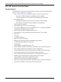

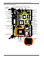
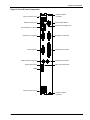


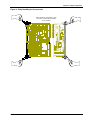
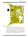

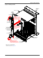

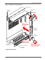
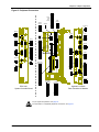


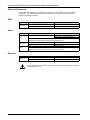
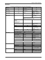
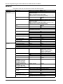

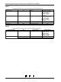

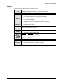
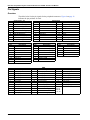
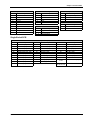
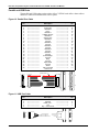


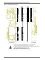


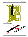
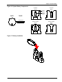


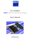
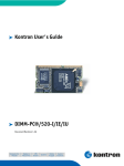
![[U2.51.02] Tracé de courbes avec Code_Aster](http://vs1.manualzilla.com/store/data/006353942_1-e8e8f885e902d20bed4f7af5be970172-150x150.png)