1
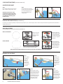
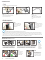
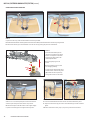
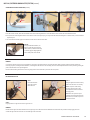
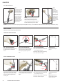
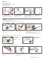
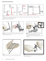
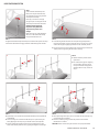
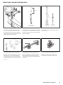
Thompson
Retractor
User Manual
SET UP INSTRUCTIONS FOR ALL THOMPSON RETRACTORS
THOMPSON RETRACTOR USER MANUAL
TABLE OF CONTENTS:
FRAMES
S-Lock Quick Frame or Spine Frame.........................................................................................4
S-Lock Bilateral Frame..............................................................................................................5
S-Lock Hinged Ring Frame.......................................................................................................6
S-Lock Bilateral Cervical Spine Frame......................................................................................7
FRAME COMPONENTS
Retractor Handle Attachment...................................................................................................8
S-Lock®.....................................................................................................................................8
Angling Retractor Handle Adjustment.....................................................................................8
Micro-Adjustable Retractor Handle Adjustment......................................................................8
Alternate Components
Infinite Height Rail Clamp (IHRC)....................................................................................9
Lower Abdominal Bar.......................................................................................................9
ILLUMINATION
Lite Wand Xe..........................................................................................................................10
Retractor Lite Xe.....................................................................................................................10
Mini Retractor Lite LED...........................................................................................................10
SPECIALTY SYSTEMS
Central Cervical Access (CCA) Retractor System......................................................................11
MIS PLA® (Posterior Lumbar Access) System...................................................................12 - 15
Laparoscopic Holders......................................................................................................16 - 17
Bolling Mitral Valve Retractor................................................................................................18
Body Contouring System.......................................................................................................19
THOMPSON RETRACTOR TIPS AND TRICKS................................................................20 - 21
ANTERIOR CERVICAL SET UP TIPS AND TRICKS...........................................................22 - 23
DO’S AND DON’TS OF INSTRUMENT CLEANING AND STORAGE......................................... 24
THOMPSON RETRACTOR USER MANUAL
3
S-LOCK QUICK FRAME OR S-LOCK SPINE FRAME [also applies to non-s-lock]
STEP 1
To secure the Elite II Rail Clamp to the
table, be sure the jaws of the rail clamp
are completely open by turning the knob
at the top of the rail clamp.
Once open, secure the rail clamp by
placing the open rail clamp jaw over the
sterile drape on either side of the table.
CAUTION: Avoid compressing
the patient’s body with frame
components to prevent nerve
damage.
When necessary, use a wider OR table or
add 2 1/2” to the width of the table by
using our Rail Extender 41917.
STEP 4
Lock the crossbar to the rail clamp by flipping
the rail clamp cam joint handle into ‘locked’
position and grasping the rail clamp for
leverage.
STEP 2
To tighten the Elite II Rail Clamp to the
table, turn the knob at the top of the
rail clamp and utilize the attached two
hanging handles for added leverage
when needed.
STEP 5
Insert the frame arms into the cam joints on the crossbar
and position the frame arms over the patient’s body low and
wide around the operating space. All cam joints should be
in ‘unlocked’ position when inserting frame arms.
COMPLETE FRAME SET UP - ABDOMINAL EXAMPLE
For retractor handles and blades, see page 8.
STEP 3
Insert the crossbar into the rail clamp and position
the crossbar approximately 3 to 5 cm above the
patient. Prior to inserting the crossbar, the cam
joint on rail clamp needs to be fully open by
flipping handle out into the ‘unlocked’ position.
STEP 6
With the frame arm positioned, flip the cam joint
handle into ‘locked’ position. To secure each arm,
grasp the frame components for leverage.
COMPLETE FRAME SET UP - CERVICAL EXAMPLE
For retractor handles and blades, see page 8.
For additional anterior cervical tips and tricks, see pages 22 - 23.
ADDITIONAL SUGGESTED SET UPS
For complete selection of suggested set ups, see the Thompson Surgical Atlas.
WE RECOMMEND RELAXING TENSION ON RETRACTORS EVERY 20 MINUTES TO ENSURE PROPER BLOOD FLOW.
4
THOMPSON RETRACTOR USER MANUAL
S-LOCK BILATERAL FRAME [also applies to non-s-lock]
STEP 1
Attach the Elite II Rail Clamp to one side of table, as shown on page 4, Steps 1 and 2. Repeat on opposite side of table with second Elite II Rail Clamp.
2
3
5
STEP 2
Insert the bilateral crossbar into the top cam joint of the rail clamp, making sure cam joints
are fully open (‘unlocked’ position) on either side of the OR table. Adjust the bilateral
crossbar’s height 8 to 10 cm (3 - 4") over the patient.
STEP 3
Lock the bilateral crossbar to the rail clamp by flipping the rail clamp handle into the
‘locked’ position and grasping the rail clamp for leverage. A rigid crossbar may be used in
place of the hinged bilateral crossbar.
CAUTION: If patient is obese, avoid compressing the patient’s body. When necessary,
use a wider OR table or add to the width of the table using a Rail Extender (41917).
4
STEP 4
Insert the angled arm into the bottom cam joint on the rail clamp and
position around the incision.
STEP 5
Lock the angled arms to the rail clamp by flipping the rail clamp handle into
‘locked’ position while grasping the rail clamp for leverage.
Repeat with the second angled arm on opposite rail clamp if desired.
STEP 6
Add retractors as needed. (See page 8.)
ALTERNATE “STAGGERED” BILATERAL FRAME SET UP
A
B
B
A
STEP 1
A Attach an Elite II Rail Clamp to the patient’s right side of the table.
B Add a rail clamp to the opposite side at the patient’s thigh.
STEP 2
A Position the upper abdominal angled arm in the rail clamp’s upper cam joint and secure it 8 to
10cm (3 - 4"), depending on desired elevation of the costal margin, above the patient’s chest.
B Position the lower abdominal angled arm in the rail clamp’s lower cam joint and position it just
above the patient’s pubic bone.
B
A
STEP 3
A Place an angled arm in the top cam joint of the lower abdominal rail clamp.
B Interconnect its distal end with that of the upper abdominal angled
arm, using 1/2" x 1/2" cam joint (42110C).
STEP 4
Add retractors as needed. (See page 8.)
THOMPSON RETRACTOR USER MANUAL
5
S-LOCK HINGED RING FRAME [also applies to non-s-lock]
UNILATERAL TABLE MOUNT
STEP 1
Attach the Elite II Rail Clamp to one side of
table, as shown on page 4, Steps 1 and 2.
STEP 2
Insert the extension arm into the
rail clamp cam joint and temporarily
lock in place by flipping the rail
clamp cam joint handle to the
‘locked’ position.
CAUTION: If patient is obese, avoid
compressing the patient’s body. When
necessary, use a wider OR table or add
to the width of the table using a Rail
Extender (41917).
BILATERAL TABLE MOUNT OPTION [not included in kit]
If necessary, for increased ring stability and especially for larger exposures, such as liver transplant, utilize a second rail clamp mounted on the opposite side of the table with an
additional extension arm.
RING FRAME ASSEMBLY
Select the appropriate sized ring frame based on the procedure size.
SMALL, CIRCULAR RING:
Mate the ring halves
together so that the
serrated faces meet
each other.
LARGE, OVAL RING:
Mate the ring halves and extensions together
so that the serrated faces meet each other.
Rotate the 2 tightening
screws clockwise to secure
the ring halves together
on each side. The ring may
be secured in a hinged or
flat position.
Rotate the 4 tightening
screws clockwise to secure
the ring halves and ring
extensions together. The
ring may be secured in a
hinged or flat position.
NOTE: Screw must be completely tightened and serrated faces must be fully seated together to ensure a secure attachment.
MOUNTING THE RING FRAME
5cm
STEP 1
STEP 2
Use an assistant
(if needed) to
position ring
frame 5cm
(2") above the
patient’s body,
surrounding the
incision site.
Unlock the cam
joint on the rail
clamp to release
the extension
arm and slide the
extension arm
toward the ring
frame.
STEP 3
Wrap the latch cam joint
jaws around the ring frame
(shown far left) and secure
by flipping the latch cam
joint handle to the ‘locked’
position while grasping
the extension arm for
leverage (shown left).
6
THOMPSON RETRACTOR USER MANUAL
STEP 4
Once ring and
extension arm are
in place, lock the
cam joint on the rail
clamp by flipping the
rail clamp cam joint
handle to the ‘locked’
position to secure.
S-LOCK BILATERAL CERVICAL SPINE FRAME [also applies to non-s-lock]
STEP 1
To secure the Elite II Rail Clamp to the table, be sure the jaws of the rail clamp are completely open by turning the
knob at the top of the rail clamp.
Once open, secure the rail clamp by placing the open rail clamp jaw over the sterile drape on either side of the
table.
CAUTION: If the patient is obese, avoid compressing the patient’s body. When necessary, use a wider OR
table or add to the width of the table using our Rail Extender (41917).
STEP 2
To tighten the Elite Rail Clamp to the
table, turn the knob at the top of the
rail clamp and utilize the attached two
hanging handles for added leverage
when needed.
STEP 3
Repeat Steps 1 and 2 to attach the second Elite II Rail
Clamp on opposite side of the table.
STEP 4
Insert the angled arms into the open cam joint on both rail clamps
parallel to the axis of the neck, 10-12cm (4 - 5") from the midline.
NOTE: To facilitate downward lateral retraction, the arm on
the surgeon’s side should be approximately 5cm (2") lower
than its counterpart.
STEP 5
Lock the angled arm in place by flipping the rail clamp cam joint
handle into ‘locked’ position and grasping the rail clamp for
leverage.
THOMPSON RETRACTOR USER MANUAL
7
HANDLES AND BLADES
RETRACTOR HANDLE ATTACHMENT
STEP 1
Clip cam joint onto frame at any location.
Handles are permanently mounted in the Cam
II clip-on joints to create a one-piece handle.
ALTERNATE STEPS 1 AND 2
Alternately, attach blade to handle first, use
handle to position blade in site, then secure
by clipping cam joint to frame.
STEP 2
Position blade in site and attach
handle to blade.
STEP 3
Retract & lock in position.
SPECIAL HANDLE AND BLADE FEATURES
S-LOCK®
All S-Lock blade and handle part numbers start with an ‘SL’ or ‘SO’ and are only compatible with other S-Lock blades and handles.
push
STEP 1: COMBINE S-LOCK
BLADE AND HANDLE
Swivel
S-Lock handles have serrated faces that
match up with serrations on S-Lock
blades for precise blade placement.
Insert S-Lock blade nipple into S-Lock
handle by pushing button.
Lock
Swivel
STEP 2: SWIVEL ALIGNS ON TISSUE
Release button with handle on the “swivel” groove
nipple setting and swivel to desired position. Ensure
the button is fully extended out of the handle to
secure.
TIP: When in swivel position, nipple should be seated
inside handle head, just below flush (as pictured).
push
STEP 3: LOCK WHEN SWIVEL IS NOT DESIRED
Lock S-Lock blade in position on the “lock” groove nipple
setting by pushing the button again and pressing straight
down over the handle to engage the serrations. Ensure
the button is fully extended out of the handle to secure.
Locked
STEP 4: RELEASING BLADES
Press button in to disengage.
TIP: To switch between two settings during use, unlock
the handle or release retraction for ease of use.
NOTE: Blades with ‘SO’ before part number
swivel only and do not lock in any orientation.
‘SO’ blades must only be used with ‘SL’ handles.
ANGLING RETRACTOR
HANDLE ADJUSTMENT
MICRO-ADJUSTABLE RETRACTOR HANDLE ADJUSTMENT
Micro-Adjustable knob provides
leverage and microadjustments for
precise blade retraction.
Blades may be angled or toed 35º in or
out with fingers or wrench for low-profile
Uncompromised Exposure.
8
THOMPSON RETRACTOR USER MANUAL
Ratcheted handle makes
for quick and easy blade
adjustment without having to
unlock cam joint.
Rotating feature provides
atraumatic alignment
on anatomy and precise blade
positioning.
ALTERNATE COMPONENTS
INFINITE HEIGHT RAIL CLAMP
STEP 1
To secure the Infinite Height Rail Clamp
to the table, be sure the jaws of the rail
clamp are completely open by turning
the knob toward the bottom of the rail
clamp counter-clockwise.
Once open, secure the rail clamp by
placing the open rail clamp jaw over
the sterile drape on either side of the
table.
Secure
Knob
Slide down
CAUTION: Avoid compressing
the patient’s body with frame
components to prevent nerve
damage.
When necessary, use a wider OR table
or add 2 1/2” to the width of the table
by using our Rail Extender 41917.
STEP 2
To tighten the Infinite Height Rail Clamp to the table, turn the knob toward the
bottom of the rail clamp clockwise, utilizing the attached four hanging handles
for added leverage when needed.
Rotate
to lock
cam joint
Rotate
to loosen
cam joint
STEP 3
Starting with the height in the tallest setting, adjust rod to the desired
height by rotating counter-clockwise to loosen the cam joint.
Slide the post down to the desired height and tighten the knob
clockwise to secure the setting. Tighten cam joint completely to lock.
STEP 4
Add frame components to rail clamp cam joint(s).
Do not attempt to adjust rail clamp height with frame components attached unless supporting the weight of the frame components with a hand.
The post will not slide easily during height adjustments if this is not done.
LOWER ABDOMINAL BAR
BILATERAL USE
STEP 1
A
A
B
A Using an assistant, insert either end
of the Lower Abdominal Bar in to the
Elite II Rail Clamp cam joint (lower
cam joint if using with a 2 cam jointed
rail clamp) on either side of the
patient.
B Position the Lower Abdominal Bar
around the incision, keeping the
lateral sides low and wide.
STEP 2
Secure the Lower Abdominal Bar by locking
the cam joints on both Elite II Rail Clamps.
UNILATERAL USE
A
A
B
STEP 1
A Using an assistant, insert
either end of the Lower
Abdominal Bar into the
crossbar cam joints on either
side of the patient.
B Position and hold the Lower
Abdominal Bar around the
incision keeping the lateral
sides low and wide.
STEP 2
Secure the Lower Abdominal Bar in position by locking the
cam joints on the crossbar.
THOMPSON RETRACTOR USER MANUAL
9
ILLUMINATION PRODUCTS
LITE WAND
If using a Retractor Lite, skip these steps and begin with Step 4.
STEP 1
Clip the Lite Wand cam joint anywhere on the
retractor frame that will allow the distal end of
the light to illuminate the incision.
STEP 2
Secure the Lite Wand in place by locking the cam joint.
STEP 3
Bend the gooseneck to position the distal
end of the Lite Wand.
NOTE: If deeper illumination is needed,
continue to Steps 4 and 5. If not, skip to
Step 6.
RETRACTOR LITE AND LITE WAND
If using a Retractor Lite, begin here.
push
STEP 4
STEP 5
Attach Lite Clip to distal end of
Lite Wand or Retractor Lite, with
the thin opening toward the
back of the lite.
While applying pressure to the
blade for leverage, slide the lite
and Lite Clip onto the desired
blade. Push all the way onto
blade to secure.
push
STEP 6
Plug Lite Wand or Retractor Lite cable into the appropriate light source and turn source on.
NOTE: If using xenon light products, be sure that the bulb in your hospital’s xenon light source is properly functioning, is turned up all of the way, and doesn’t need to be
replaced. A bulb that has been used over 700 hours can reduce light by up to 30%. Also, replacing bulbs with less expensive “off-brand” bulbs can cause light reductions in
lighting accessories such as ours. Light sources should be Xenon only, 300W. Lastly, check to make sure your light source properly fits our Lite Wand Xe and Retractor Lite Xe
plugins. An improper fit will reduce light emissions. We provide adapters for Olympus, Storz, and Wolf light sources if needed.
MINI RETRACTOR LITE LED [cervical use only]
STEP 3
STEP 1
Press distal end of Mini Retractor Lite (40002MRL) into
Mini Lite Clip (40026MRL). Apply pressure to the rigid
metal portion of the light only to avoid damaging cable.
STEP 2
Slide Mini Lite Clip and Mini Retractor Lite on to retractor blade (clip is intended
to be used with Thompson anterior cervical blades). Adjust clip so that the light
emitting end of Mini Retractor Lite is unobstructed and points down blade face.
STEP 4
Reduce cable tension
to prevent clip from
moving on the blade.
P
10
THOMPSON RETRACTOR USER MANUAL
Do not block light.
Plug Mini
Retractor Lite
cable into LED
Light Source
(LLS-2000) and
turn source on.
OPTION
S-Lock may be utilized to rotate
blade without affecting clip
position in most cases. If clip
position is affected, move clip
and light to a different blade.
CENTRAL CERVICAL ACCESS (CCA) RETRACTOR SYSTEM
For frame set up, see Bilateral Cervical Spine Frame, page 7.
BLADE PLACEMENT AND HANDLE ATTACHMENT
STEP 1
Use the Depth Gauge to
select the appropriate
blade length and attach
the Manipulator Handle
to the blade as shown.
STEP 2
Holding the Manipulator Handle, place the
first blade, driving the blade tip in to the
anterior aspect of the spine. Use extreme
caution at C6/C7 and in all areas where the
patient’s vertebral artery runs more anteriorly.
A
Plunger
Swivel
B
STEP 4
To secure the blade, attach an S-Lock® Hinge
to the blade nipple.
STEP 7
Retract the handle back and remove the manipulator
handle. Secure the retraction by turning the Clip Clip
knob to tighten the joint.
Locked
STEP 3
Attach a Clip-Clip Joint to the Angled Arm
nearest to the blade placed in Step 2 as
shown.
STEP 5
A Insert the blade nipple into the
handle by pushing the plunger.
Release the plunger with the
handle on the “Swivel”groove
and swivel the blade to the
desired position.
B If desired, lock the blade
in position by pushing the
plunger again and pressing
straight down over the handle.
DO NOT use bone levers with
non-hinged S-Lock handles.
Bone levers may only be used
with SL45003LH or SL42126LH.
STEP 6
Attach the S-Lock® Hinged Handle to
the Clip Clip Joint. The S-Lock® Hinged
Handle will slide freely in the joint.
STEP 8
Place an additional blade across from the first and add blades to
the adjacent levels to be visualized.
THOMPSON RETRACTOR USER MANUAL
11
MIS PLA® (POSTERIOR LUMBAR ACCESS) SYSTEM
TABLE MOUNT
B
B
18-24"
C
A
A
STEP 1
A Attach the Elite II Rail Clamp jaw to the table rail 45 - 65cm (18-24”) away
from the site of operation on either side of the table over the sterile drape.
B To secure, turn the knob at the top of the rail clamp and utilize the
attached hanging handles for added leverage when needed.
TIP: Position so that the rail clamp will not interfere with imaging equipment.
CAUTION: If patient is obese, avoid compressing patient’s body. When
necessary, use a wider OR table or add to the width of the table using Rail
Extender (41917).
STEP 2
A Insert the Articulating Arm into the rail clamp cam joint.
B Ensure the distal end of the arm can reach the site of operation with several
inches of flexibility.
C Rotate the arm out of the working area until ready to be used and lock to the
rail clamp by flipping the rail clamp cam joint handle to the “locked” position,
grasping the rail clamp for leverage.
TIP: If a larger range of motion is needed, move the rail clamp closer to operation
site. If arm is too close, move the rail clamp farther from the operation site.
SEQUENTIAL DILATION
STEP 3
A After the incision is made, insert the first dilator and sequentially add the next three dilators.
B Take note of the depth marked on the dilator that is closest to the skin for blade length selection.
TIP: Use caution holding dilators to avoid dropping. Do not use dilators if they are deformed or
dented.
A
B
ASSEMBLE THE MIS SPINE FRAME
A
B
press pawl with finger
C
STEP 4
A Assemble the frame beginning by holding the rack with the toothed side facing away.
B Slide the Left and Right Frame Arms on to the rack so that the buttons are pointing outward.
C The left arm should be on the assembler’s left and the right arm should be on the assembler’s right.
center line
press
STEP 5
A Select the Left and Right Caudal/Cephalad (C/C) Blade that
corresponds with the depth noted in Step 3. Attach the blade
marked “L” to the left frame arm by pressing the button on the
arm and inserting the blade nipple into the arm, then releasing
button to secure connection.
B Repeat steps to attach the blade marked “R” to the right arm.
12
THOMPSON RETRACTOR USER MANUAL
STEP 6
Press down the pawls located on each frame arm near the rack to slide the frame
arms together. Center the arms on the rack for maximum retraction potential.
TIP: Ensure the blades are touching to enable a close fit with the dilators. If blades
are not aligned straight, check to make sure the frame arms are not angled. If
the arms are angled, locate the angling nut in Step 12 and turn in the opposite
direction until blades meet.
MIS PLA® (POSTERIOR LUMBAR ACCESS) SYSTEM [continued]
OBTAIN EXPOSURE
B
A
C
STEP 7
Slide the caudal/cephalad blades attached to the frame over the
dilators and rotate the frame so that the frame rack runs parallel to
the spine.
TIP: Hold blades together at the neck during insertion over
dilators for the smoothest step transition.
TIP: Point the rack away from the surgeon for a larger working area.
STEP 8
A Loosen the knurled knob on the distal end of the Articulating Arm.
B Loosen the black knob (knob shown in step 9B) on the Articulating Arm and pull the
distal end of the arm toward the frame rack. Unlock the cam joint on the rail clamp if
needed. Insert the distal end of the arm over the end of the frame rack.
C Tighten the knurled knob on the distal end of the arm to lock the frame to the table mount.
TIP: Use an assistant to hold the frame and blades steady while attaching to the table mount.
B
A
STEP 9
Hold frame in position while an assistant (A) locks the cam joint on the rail clamp
then (B) tightens the black knob.
STEP 10
Remove the dilators in one step by pulling up on the initial dilator.
Use caution handing dilators to avoid dropping.
TIP: If adjustments are needed, simply loosen the black knob to add flexibility to the
arm. Reposition the frame and then re-tighten the black knob.
TIP: If friction occurs between the dilators and the blades, hold the
frame in position as the dilators are removed to prevent the frame
from rising up.
TIP: Arch the section of the arm with the black knob upwards to add counter pressure
to the frame and to allow for easy access to the knob if adjustments are needed.
STEP 11
Retract blades independently to the desired exposure by turning the nut closest to the
frame rack labeled “OPEN” using the T-Handle. To reverse retraction, press the pawl
located on the frame arm as done in Step 6.
STEP 12
Angle blades independently to the desired exposure by turning the
nut labeled “ANGLE” using the T-Handle. To reverse the angle, turn
the T-Handle in the opposite direction.
THOMPSON RETRACTOR USER MANUAL
13
MIS PLA® (POSTERIOR LUMBAR ACCESS) SYSTEM [continued]
ADDING MEDIAL/LATERAL RETRACTION
A
B
STEP 13
To prevent muscle creep, medial and lateral blades or hooks may be added.
A If medial and lateral retraction is desired, place the L-Bar over the Frame Rack, outside of the Frame Arms and secure by turning the knob.
B To add a lateral retractor, place the U-Bar Add-on on to the L-Bar rack by pressing the pawl on the U-Bar Add-on.
STEP 14
Select the desired blade style/s for
retraction in the medial and/or lateral
direction in a depth that is 10-20mm
longer than the depth used for the
caudal/cephalad blades.
A
swivel
or
lock
A Press the gold plunger on the
handle.
B
B Insert the blade(s) in to the S-Lock
Cam II Angling Handle(s)
1
In the first groove (1), the blade will be
allowed to swivel. In the second groove
(2), the blade will lock in position by
mating with serrations on the handle.
2
tighten
retract
A
STEP 15
Slide the 1/4" x 1/4" Side Clip Slide joint over the end of the L-Bar
with the clip side of the joint and the knob on top as shown.
TIP: Do not allow joint to slide off of the U or L-Bar. Tighten slightly
to prevent it from sliding but do not tighten all the way down.
14
THOMPSON RETRACTOR USER MANUAL
clip
B
STEP 16
A Insert the medial/lateral blade into the incision and retract handle back by hand.
B Snap the handle into the clip joint and turn the knob with fingers or with T-Handle to
tighten.
TIP: If the handle does not easily snap in, the joint may need to be loosened first.
MIS PLA® (POSTERIOR LUMBAR ACCESS) SYSTEM [continued]
ADDING MEDIAL/LATERAL RETRACTION [continued]
tighten
retract
retract
A
B
C
STEP 17
A To add a lateral retractor, attach the desired blade to the S-Lock Interchangeable Head. Insert the blade in to the incision and retract towards the U-Bar.
B Snap the S-Lock Interchangeable Head on to the U-Bar. If it does not easily snap on, joint may need to be loosened with fingers or T-Handle. To lock, use the T-Handle to
tighten the joint.
C To retract the lateral blade, apply the T-handle to the U-Bar where it attaches to the L-Bar.
STEP 18
To angle medial/lateral blades, use
fingers to rotate the knurled portion
of the handle or, if additional leverage
is needed, apply the Angling Wrench
to the hexed portion of the handle.
REMOVAL
To remove the retractor, begin by returning all blades to a straight up and down position by unangling all blades. Next, remove the medial and lateral retractors by
loosening the joints, removing handles and blades, and sliding them off of the U or L-Bar. Carefully, return the caudal/cephlad blades to the start position by pressing the
pawl so that the blades can be pushed together.
Dismount the Articulating Arm from the frame and gently pull the frame and blades up to remove from the patient.
MIS RETRACTOR LITE LED
STEP 1
Insert the distal ends
of the light into the
blade channels.
STEP 2
Swing the light ends back so that they
hook under the frame arms securely.
TIP: Do not pull on cable during
this step, apply pressure to rigid,
metal portion of distal end to avoid
damaging cable.
TIP: More or less pressure may be
needed to secure the light ends under
the frame arms, variations in pressure
needed are normal.
STEP 3
Plug light cable in to light source and turn light source on.
REMOVAL
DO NOT remove lights from blades without first turning the light source off. Please refer to MIS Retractor Lite LED IFU for all precautions. Gently apply pressure to
unhook the light ends from the frame arms and slide light ends out of blade.
THOMPSON RETRACTOR USER MANUAL
15
LAPAROSCOPIC
ELITE II RAIL CLAMP SET UP
STEP 1
To secure the Elite II Rail
Clamp to the table, be
sure the jaws of the rail
clamp are completely
open by turning the
knob at the top of the
rail clamp. Once open,
secure the rail clamp
by placing the open
rail clamp jaw over the
sterile drape on either
side of the table.
STEP 3
Insert the
holder into the
rail clamp and
lock in place by
flipping the rail
clamp cam joint
handle into the
locked position
while grasping
the rail clamp for
leverage.
STEP 2
To tighten the Elite II Rail Clamp to the
table, turn the knob at the top of the rail
clamp and utilize the attached two hanging
handles for added leverage when needed.
CAUTION: If the patient is obese, avoid compressing the patient’s body. When necessary, use a wider OR table or add to the width of the table using our Rail Extender (41917).
HOLDER ADJUSTMENT
Follow the instructions for adjusting preferred holder
LAPAROSCOPIC ARTICULATING ARM
B
A loosen
C tighten
STEP 1: RELEASE ARM TENSION
Release the tension of the arm by turning
the black knob counter-clockwise to
loosen.
STEP 2: ADJUST ARM POSITION
Position the arm ensuring it will allow the
scope or instrument to reach the incision.
Lock into place by tightening the black
knob.
STEP 3: ADD AN ATTACHMENT
A Turn the knurled knob on the distal end
counter-clockwise to loosen.
B Insert the attachment into the opening.
C Turn knob clockwise to tighten.
COMPLETE SET UP
See ‘Attachments’ steps on
page 17.
FLEXIBLE LAPAROSCOPIC HOLDER
B
A loosen
C tighten
STEP 1: SECURE POSITION
Position the arm ensuring it will allow the
scope or instrument to reach the incision.
Secure the position by tightening the
universal joint.
16
STEP 2: ADJUST ARM TENSION
Turn the hanging handle to adjust tension:
counter-clockwise to loosen, clockwise to
tighten.
THOMPSON RETRACTOR USER MANUAL
STEP 3: ADD AN ATTACHMENT
A Turn the knurled knob on the distal end
counter-clockwise to loosen.
B Insert the attachment into the opening.
C Turn knob clockwise to tighten.
COMPLETE SET UP
See ‘Attachments’ steps on
page 17.
NOTE: Always loosen arm
tension before moving the
scope or instrument.
LAPAROSCOPIC [continued]
HOLDER ADJUSTMENT [continued]
Follow the instructions for adjusting preferred holder
RIGID LAPAROSCOPIC HOLDER
STEP 1: POSITION HEIGHT
Adjust height by unlocking the cam joint and
moving the holder up or down, then secure.
STEP 2: POSITION DISTAL END
Position the distal end of the holder and
tighten the universal joint.
STEP 3: ATTACH INSTRUMENT
Loosen the joint on the distal end and insert
laparoscopic instrument into the opening.
Tighten the joint to secure.
COMPLETE SET UP
Shown with Nathanson Hook
attached.
ATTACHMENTS
Follow the instructions for attachment of choice
SCOPE GRIP AND BUSHING [Holds the scope tightly, and prevents rotation of angled scopes]
STEP 1
Open the Scope Grip by turning the joint counterclockwise.
STEP 2
Insert scope into bushing.
STEP 3
Insert scope and bushing into Scope Grip. Position scope and turn
the joint clockwise to tighten, securing in place.
NOTE: To reposition scope, joint on holder may need to be loosened.
SCOPE CLIP [Provides a less firm hold for quick in and out panning of flat scopes]
STEP 1: INSERT SCOPE
Insert scope into the Scope Clip and
position.
STEP 2: EASILY ADJUST
Scope may be easily adjusted for
in and out panning.
NOTE: Scope Clip is reusable.
DUO HEAD [Holds the laparoscopic instrument securely in place]
STEP 1
Open the Duo Head by turning the joint counterclockwise.
STEP 2
Insert laparoscopic instrument into one side of the
Duo Head and position.
STEP 3
Turn the joint clockwise to tighten, securing in place.
THOMPSON RETRACTOR USER MANUAL
17
BOLLING MITRAL VALVE RETRACTOR
T-Bar 8"
(47201N)
L-Bar 2" (47200N)
L-Bar 2" (47200N)
L-Bar 6" x 8" (47202N)
STEP 1
With sternal spreader in place, determine where retractor blades will be needed. Select T- or L-Bar clamp(s) of choice to allow for mounting of retractor blades.
(See examples above, other configurations are possible.)
NOTE: Custom bar dimensions are available.
STEP 2
Turn knurled knob on the clamp counter-clockwise to open, place over spreader, and turn
knob clockwise to tighten until secure.
STEP 3
Slide joint onto bar where retractors are needed. To avoid suture snags,
position the knob toward the bottom of the bar as shown.
Alternately, the knob may be positioned toward the top for easier access
(inset photo).
STEP 4
Select shortest retractor necessary for patient size. Three lengths are provided.
18
THOMPSON RETRACTOR USER MANUAL
STEP 5
Insert retractor into joint, retract anatomy, and lock joint by turning knob clockwise.
Repeat for additional retractors.
BODY CONTOURING SYSTEM
STEP 1
To secure the Elite II Rail Clamp to the
table, be sure the jaws of the rail clamp
are completely open by turning the knob
at the top of the rail clamp.
Once open, secure the rail clamp by
placing the open rail clamp jaw over the
sterile drape on either side of the table.
CAUTION: Avoid compressing
the patient’s body with frame
components to prevent nerve
damage.
A
B
When necessary, use a wider OR table or
add 2 1/2” to the width of the table by
using our Rail Extender 41917.
STEP 2
To tighten the Elite II Rail Clamp to the table, turn the knob at the top of the rail clamp
and utilize the attached two hanging handles for added leverage when needed.
STEP 3
A Insert the 90º grooved rod into the rail clamp with the grooved portion in
the horizontal position. Prior to inserting the rod, the cam joint on rail clamp
needs to be fully open by flipping handle out into the ‘unlocked’ position.
B Lock the rod to the rail clamp by flipping the rail clamp cam joint handle into
‘locked’ position and grasping the rail clamp for leverage.
STEP 4
B
A
A Slide the Towel Clip Cranks over the
grooved rod.
B For unilateral setup (pannus weighing
less than 25lbs), skip step 5 and go
to step 6. For bilateral setup (pannus
weighing 25lbs or more), continue to
step 5.
C
B
B
A
STEP 5
A Repeat Steps 1 and 2 to attach the second Elite II Rail Clamp on the opposite side
of the OR table.
B Insert the straight arm into the Elite II Rail Clamp’s cam joint vertically and
lock by flipping the rail clamp cam joint handle into the ‘locked’ position.
C Insert the grooved rod into the straight arm cam joint and flip the cam joint
handle to the ‘locked’ position to secure, grasping the straight arm for leverage.
A
STEP 6
A Attach perforating towel clips to pannus as needed and loop the finger rings
over the Towel Clip Crank hooks.
B Retract as needed by turning the Towel Clip Crank’s knobs clockwise.
Add retractors as needed.
CAUTION: Release retractors every 20 minutes to ensure proper blood flow.
THOMPSON RETRACTOR USER MANUAL
19
THOMPSON RETRACTOR TIPS AND TRICKS
ISSUE:
“The crossbar sticks out
and in the way”
SOLUTION:
The crossbar was designed
for versatility, it can be raised
and lowered while also being
rotated. The key is to remember
to rotate the crossbar so that if
there is any excess length, it is
pointing out of the way.
Rotate the crossbar and
point excess length out of
the way, lower the crossbar
height as needed
ISSUE:
“There is no room to
add a handle or cam
joint to the crossbar”
SOLUTION:
Rotate the cam joint
handles out of the
way so that they don’t
block the crossbar
before locking them
down
Handles or cam joints
can be attached
between the two cam
joints as long as the
cam joint handles are
locked out of the way.
ISSUE:
“The retractor handle
won’t reach far enough”
SOLUTION:
Attach the retractor handle cam
joint so that the cam joint is on
the inside of the frame. It will
provide more reach. If this is
still not enough room, move
the angled arms closer to the
operative site.
The retractor handle might
not be reaching far enough
if the arms are too far apart,
or if the retractor handle
cam joint is attached on the
outside of the frame.
ISSUE:
“The retractor handle sticks out in
the working area”
Retractor handle cam joints and the blades
attached to the handles can rotate 360º
so the handles do not have to lock back in
the direction they are rectracting. If using
S-Lock Technology blades and handles, the
blade can be locked in any orientation to
the handle so that it doesn’t swivel if the
handle is rotated out of the way.
20
THOMPSON RETRACTOR USER MANUAL
A
A
SOLUTION:
A Rotate the handle so that it angles
away from you before locking.
Rotate the blade so that it still
retracts in the desired position.
B Utilize S-Lock blades and handles
to prevent blade swivel.
B
B
THOMPSON RETRACTOR TIPS AND TRICKS [continued]
B
A
A
LOW
AND
WIDE
ISSUE:
“There’s no room to retract further”
SOLUTION:
If the angled arms are set up too close, retraction space may be limited.
Additionally, the handle cam joints can take up retraction space and the
handle can reach maximum retraction early when it runs into the cam joint
like the two bottom handles in the photo above.
ISSUE:
“The retractor is up too high and it feels like I’m working in a
tunnel”
If the angled arms and crossbar are positioned up too high, the handles will be
forced to angle downward to reach the incision adding to the tunnel effect and
causing the handles to stick up. The crossbar only needs to be about 5cm (2") off
of the patient and the angled arms can go lower as long as they don’t touch the
patient or block imaging.
A Open up the angled arms to create a wider frame and point handles away
from your working space.
B For more retraction room, attach handle cam joints with the bulk on the
outside of the arm.
SOLUTION:
Lower the crossbar (shown) and/or angled arms as necessary. The angle
in the arm allows you to lower the arm while keeping a portion of it
parallel to the ground for an even set up. Using angling handles will aid in
lowering the overall profile as well.
Alternately, the angled arms may be set up low and wide, see photo above.
ISSUE:
“It is difficult to remove
the Micro-Adjustable
Handle from the
Retractor Frame”
Micro-Adjustable Handles
clip securely onto the frame
and will not fall off. This may
cause some difficulty when
trying to un-clip the handle
from the frame.
SOLUTION:
To easily remove clip on cam joints from arms, “pinch” the back of the cam
joint using thumb and index finger. Gently lift up off of arm.
THOMPSON RETRACTOR USER MANUAL
21
ANTERIOR CERVICAL SET UP TIPS AND TRICKS
ELITE II RAIL CLAMP
Placement: The rail clamp should be attached to the bed rail in line with the top of the patient’s head.
TIP: If the rail clamp height is in the way, consider using the 11" rail clamp for a lower profile working area.
Or utilize the Infinite Height Rail Clamp if sharing the frame for lumbar procedures (see next page).
TIP: The rail clamp may be positioned on either side of the table if obstructing the surgeon or assistant’s movements.
TIP: The rail clamp may be positioned at the patient’s shoulder if no rail space is available near the patient’s head, or if the rail
clamp is more out of the way near the patient’s shoulder. Ensure the rail clamp will not interfere with imaging of the affected
cervical levels. (See next page.)
TIP: If no rail space is available near the patient’s head, but the rail clamp is desired near the patient’s head, utilize a rail extender
(see next page).
CROSSBAR
Placement: The crossbar should be positioned 2-3 fingers, level, above the patients head. (See next
page for an alternate set up that eliminates the crossbar.)
TIP: If more space is needed above the patient, the crossbar may be rotated upward.
TIP: When accessing uppermost cervical levels, an extension arm can be added to the crossbar to
help facilitate the appropriate angles of retraction.
TIP: The crossbar may also be placed over the patient’s chest depending on where the rail clamp is
set up (see next page).
ANGLED ARMS
Placement: Position arms “low and wide” creating a low profile working area and ensuring
enough distance for handle retraction.
TIP: Keep arms level with the incision. Placing too low may interfere with imaging. TIP: The 18" Arms have 8" and 10" sides. For more “reach” place the 8" portion in the crossbar.
TIP: When securing the arms to the crossbar, ensure the cam handle on the cam joint is in the
same plane as the arms and not over the center of the crossbar taking up real-estate for the
handles to be attached.
HANDLES
RADIOLUCENT BLADES
Placement: Handles can be clipped on to the arms or the crossbar at
any location.
Placement: Blades may be positioned in the head and toe direction as well as medially
and laterally. Blades may be positioned for 1-4 levels of exposure from upper to lower
cervical regions.
TIP: Use the
S-Lock® feature
to lock blades
securely in place,
while moving the
retractor handle
out of the way
on the surgeon’s
access side.
TIP: Most often, the need for toothed blades is eliminated through the use of a table mount.
Concave
Medial / Lateral
35 - 80mm lengths
TIP: Utilizing S-Lock® technology, blades are easily placed by locking the
blade in place on the handle and using in the same manner as a handheld retractor to position. Once in place, the handle may be clipped
onto the frame and secured.
22
THOMPSON RETRACTOR USER MANUAL
Midline
Mandible
Left and Right blades
Concave Tapered
Medial / Lateral
35 - 70mm lengths
Micro
Microdiscectomy
35 - 60mm lengths
Odontoid
Odontoid / Longitudinal Cephalad
20mm x 90mm
Longitudinal
Longitudinal
30 - 70mm lengths
Malleable
Longitudinal Cephalad
Multiple sizes available
ALTERNATE PRODUCT SOLUTIONS FOR ANTERIOR CERVICAL
13-22"
Infinite Height
Rail Clamp
18" Elite II
Rail Clamp
11" Elite II
Rail Clamp
ALTERNATE RAIL CLAMP PLACEMENT
INFINITE HEIGHT RAIL CLAMP
11" ELITE II RAIL CLAMP
The rail clamp may also be placed at the patient’s
chest level as an alternate to the standard anterior
cervical frame set up. The rail clamp and crossbar are
positioned at the patient’s chest, with the angled arms
attached toward the head, low and wide.
An alternate option to the Elite II Rail Clamp, the Infinite
Height Rail Clamp can easily be adjusted to any height
between 13" and 22" and can be utilized with the spine
frame for any exposure.
For an even lower profile, you may choose to use the 11"
Elite II Rail Clamp.
BILATERAL CERVICAL SPINE FRAME
RAIL EXTENDER
JACKSON FRAME ADAPTER
If a lower profile, bilateral option is preferred, the
Bilateral Cervical Spine Frame may be used. Dual 11"
Elite II Rail Clamps, our smallest Elites ever, offer a
low profile bilateral frame to increase frame stability,
increase working space, and reduce frame set up time.
If the OR table rail does not extend past the patient’s
head, a rail extender may be needed. The rail extender
attaches to the OR table rail and adds length to the rail
where needed. The rail clamp can then be secured to the
rail extender.
If using a Jackson spine table, the Jackson Frame
Adapter may be connected to the table to add a
standard bed rail to attach the Thompson frame.
See page 7.
THOMPSON RETRACTOR USER MANUAL
23
DO’S AND DON’TS OF INSTRUMENT CLEANING, STORAGE, AND INSPECTION
DO
DO NOT
Check that all parts have been properly cleaned and sterilized and
that no unacceptable stains or residues are present on parts.
Use parts with residue—call Thompson if you have
questions on staining or residues.
Always pre-clean instruments before placing into sterilizer.
Sterilize instruments without pre-cleaning; blood/debris
can embed and cross-contaminate.
Use low to average pH products/cleaning agents.
Use distilled water when soaking instruments
Use high pH products or those containing chloride; will
strip protective layer on metal and cause rust.
Always ensure instruments are completely dry before storing.
Use saline when soaking instruments
Always store instruments in clean condition; in a dry & sterile
environment.
Store instruments wet or semi-dry; will stain and corrode
the metal.
Protect instruments when storing; wrap instruments or use
instrument case trays.
Store instruments dirty; debris can contaminate and rust
the metal.
Always keep instrument handles UNLOCKED (open) when not in use.
LOCK instrument handles down when not in use; will
damage/collapse cam joints.
Only LOCK down cam joint handles when rods are present or in place.
Always UNLOCK (open) handles before adjusting rods or
disassembling equipment.
Ensure cam joint holes have smooth inner surface, free of scratches
or burs, before inserting rods.
Ensure rod surfaces are smooth, free of gouges/scoring, before
placing into cam joint holes.
Carefully align screw knobs to smoothly tighten/engage threads.
(Keep threads clean and lubricated.)
Always depress blade handle release button while attaching/
detaching blades.
24
THOMPSON RETRACTOR USER MANUAL
LOCK handles without rods in place; will collapse/distort
settings.
Adjust rods while cam joint handles are LOCKED down;
twisting/force will damage both pieces.
Insert rods into damaged cam joint holes (force fit); will
damage both pieces.
Insert damaged rods into cam joint holes; will damage
both pieces.
Screw down knobs with threads misaligned; will strip/
cross threads (dirty threads will jam knobs).
Pull blades from handles without depressing handle
release button; will damage blade & nipple.
Rev B
121515
trumeng1215
10170 East Cherry Bend Road
Traverse City, Michigan 49684
phone: 231.922.0177
fax: 231.922.0174
thompsonsurgical.com
EC
REP
Emergo Europe
Molenstraat 15
2513 BH, The Hague
THE NETHERLANDS
0297
© 2015 Thompson Surgical Instruments, Inc. Traverse City, Michigan.
® S-Lock® , PLA®, and the “T Circle” logomark are Registered Trademarks of Thompson Surgical Instruments, Inc.
Patents: US4971038, US5025780, US5888197, US5897087, US5902233, US5984865, US6033363,
US6416465, US6511423, US7338442, US7749163, US8257255, US8360971, US8617064.
Other patents pending.
The MIS Retractor Lite LED (40002MIS), Mini Lite Wand LED (40020LE) and LED Light Source (LLS-2000)
are manufactured by Sunoptic Technologies® and distributed by Thompson Surgical Instruments.
Made in the USA