1
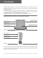
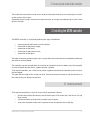
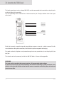
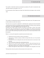
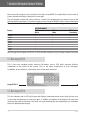
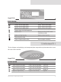
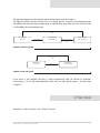
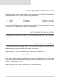
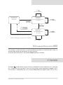
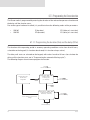
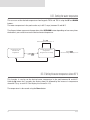
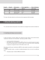
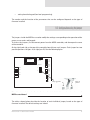
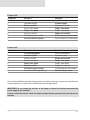
MSPA CONTROLLER
INSTALLATION AND USER MANUAL
2
Astrel
Index
1. General warnings
1.1. Responsibility of the user
1.2. Accessing the live parts
1.3. Precautions when handling the board
1.4. Installation tips
1.5. Disposal and cleaning
05
05
06
06
07
07
2. General description
2.1. Accessing the inside of the controller
08
09
3. Installing the MSPA controller
3.1. Fastening vertically
3.2. Fastening horizontally
3.3. Connection to the power supply
3.3.1. General description
3.3.2. Single-phase connection, 1 x 32 A
3.3.3. Two-phase connection, 2 x 16 A
3.3.4. Three-phase connection 3 x 16 A
3.4. Connecting the 230 Vac loads
3.5. Connecting the light
3.6. Connecting the external units
09
09
10
11
11
12
12
13
14
15
15
4. Starting for the first time
16
5. Description of the keypad and functions of the buttons
5.1. Main keypad TSC-4
5.2. Main keypad TSC-8
5.3. Auxiliary keypad TSC-3
18
18
19
19
6. Main functions
6.1. Pump 1 function 1
6.2. Pump 1 function 2
6.3. Pump 1 function 3
6.4. Blower function
6.5. Light function
6.6. Clean water function
6.6.1. Purge function
6.6.2. Filter function
6.6.3. Accelerated filtering function (boost)
6.7. Econo function
6.7.1. Programming the econo function
6.7.2. Economy mode timeout
20
20
21
22
22
23
23
24
25
27
27
28
29
MSPA controller - Installation and user manual
3
6.8. Clock function
6.8.1. Displaying the time
6.8.2. Setting the clock
4
29
29
29
7. Secondary user functions
7.1. Keypad lock
7.2. Inverting the display
7.3. Disabling the controller outputs (standby)
7.4. Temperature unit of measure
7.5. Filter maintenance signal
30
30
31
31
32
32
8. Automatic functions
8.1. Power-up signal
8.2. Controlling the water temperature
8.2.1. Setting the water temperature
8.2.2. Setting the water temperature above 40°C
8.3. Smart winter mode
8.4. Mains power input management
8.4.1. Single-phase or two-phase plus neutral power supply
8.4.2. Three-phase plus neutral power supply (laing heater)
32
32
33
34
34
35
35
35
35
9. Setting the operating parameters
9.1. Identifying the firmware version installed
9.2. Configuration using the jumper
9.3. Settings from the main keypad (low level programming)
36
36
37
39
10. Optional accessories
40
11. Error messages
41
12. Maximum dimensions
42
13. Technical specifications
13.1. General characteristics
13.2. Output specifications
13.3. Signal connections
43
43
43
44
Astrel
1. General warnings
Before installing or operating on the appliance, read carefully and follow the instructions contained
in this manual. The information on installation refers to the electrical connections. No information
is provided on the mechanical or plumbing fittings for connecting the MSPA controller to the
minipool.
This manual is an integral part of the product and therefore must be kept for future reference.
Astrel S.p.A. reserves the right to make any modifications it considers necessary without prior
warning or replacement.
1.1. Responsability of the user
The device described in this manual has been manufactured to operate risk-free and for the specific
purpose, as long as:
•
•
the device is installed, programmed, operated and serviced according to the instructions in
this manual;
the environmental conditions and the power supply are within the specified limits.
All other uses and modifications made to the device that are not authorised by the manufacturer are
considered incorrect.
Liability for injury or damage caused by the incorrect use of the device lies exclusively with the
user.
In the event of faults or malfunctions of the product under warranty, contact authorised technical
personnel only.
The manufacturer is not liable for any damage caused by products that have been tampered with or
repaired incorrectly.
MSPA controller - Installation and user manual
5
1.2. Accessing the live parts
This device contains live electrical components. Consequently, all the service and maintenance
operations must be performed by expert and qualified personnel, after having taken the necessary
precautions.
As the MSPA controller does not feature any internal systems for disconnecting the power supply,
the power line must be fitted with disconnecting and protection devices compliant with the
standards in force in the country of installation.
Before accessing the inside parts, the unit must be disconnected from the mains power supply
using a disconnecting switch.
1.3. Precautions when handling the board
To avoid damage of an electrostatic nature to the board, the following precautions must be
adopted.
•
Before handling the controller, the board or any electronic component, touch a grounded
object so as to discharge the electrostatic charges present on the body and on the
clothing.
•
The materials must remain as long as possible inside their original packages; when having
to remove the board from the antistatic packaging, touch it as little as possible.
•
Never use plastic, polystyrene or non-antistatic sponge bags for packaging the board.
Never pass the unpackaged boards, as described previously, between operators (to avoid
electrostatic induction and consequent discharges).
6
Astrel
1.4. Installation tips
The following suggestions should be heeded to prevent potential problems during the life of the
product:
• do not install the controller in environments with high levels of relative humidity, exposure
to direct pressurised jets of water, high levels of magnetic and/or radio frequency
interference.
• use cable ends suitable for the corresponding terminals and the cross-section of the
wires used; tighten the cable terminals and slightly tug the cables to check that they are
sufficiently tight.
• separate as much as possible probe cables, keypad cables and sensor cables from the
power lines and cables supplying power to the inductive loads.
• protect the controller and the user with suitably rated electrical protection devices, in
compliance with the standards in force of the country of installation.
1.5. Disposal and cleaning
The controller is made up of metal and plastic parts. These should be disposed of according to the
local legislation in force.
The controller should be cleaned only outside using neutral detergents and/or water.
MSPA controller - Installation and user manual
7
2. General description
The MSPA series controllers are electronic controllers used in spas (or minipools). These are
whirlpool tubs fitted with stations for multiple users, which include a system for heating, filtering
and sanitising the water.
The MSPA controllers can manage the functional loads (that is, the loads controlled by the user)
such as the whirlpool pumps, the blower and the lights, and the “service” loads, such as the heater
and the ozonizer, which are controlled without the user acting directly.
The MSPA controllers can also be connected to a number of optional accessories.
Externally, the controller has a plastic case with IP65 index of protection.
Pump connectors
Keypad and optional
accessory cable inputs
Power cable input
230 Vac connectors
Cover to remove to access the
board and the terminal block
Front view
Pump connectors
Power cable input
230 Vac connectors
Left view
As can be seen in the figure above, the left side has J&J connectors for connecting the 230 VAC
loads. On the right side, on the other hand, are openings for passing the connection cables to the
keypads and to the optional external units.
8
Astrel
2.1. Accessing the inside of the controller
The inside of the controller can be accessed by removing the front cover, unscrewing the 4 screws
on the corners of the cover.
Depending on the model, the electronic board may be or may be not protected by a cover sheet
(plastic or metal).
3. Installing the MSPA controller
The MSPA controller is installed by following the steps listed below:
•
•
•
•
•
mounting (on the horizontal or vertical plane);
connection to the power supply;
connection of the loads;
connection to the external units;
connection of the lights.
The order shown for performing the steps is purely indicative and needs to be adapted according to
the features of the minipool.
The controller can be secured either on a vertical or horizontal surface. In both cases, the controller
must be fastened onto the plastic support bracket, supplied.
To fasten the controller, use screws to secure the support bracket and the controller to the structure
of the minipool.
The type and the length of the screws must be chosen based on the features and the thickness of
the material they are being screwed into.
3.1. Fastening vertically
To fasten the controller to a vertical surface (wall), proceed as follows:
• position the bracket horizontally so that the flat part sticks to the wall, and secure it using
three screws.
• clip the controller to the bracket using the special guides;
• secure the controller to the wall using two screws through the slots at the top.
MSPA controller - Installation and user manual
9
Front view.
Position of the
slots for fastening
the controller.
Left view.
Position of the
guides for clipping
the controller to
the plate.
3.2. Fastening horizontally
Before fastening the controller to a horizontal surface, make sure that the surface is flat and not at
an angle. Then proceed as follows:
• secure the support bracket to the surface, using three screws; the bracket should be
positioned with the flat bottom facing downwards.
• press the controller against the bracket until the bottom of the controller clips onto the
bracket;
• fasten the pack support to the surface with two screws in the special guides located on the
base.
If the controller has been fastened correctly it will not be able to move in any direction.
Front view.
Position of
the guides for
fastening the
controller.
10
Left view.
Position for
clipping the
controller to the
plate.
Astrel
3.3. Connection to the power supply
IMPORTANT:
Read carefully this paragraph before connecting the controller! Failure to observe the instructions
contained in this paragraph may cause serious damage to the controller and to the other electrical
devices installed.
3.3.1. General description
To connect to the power supply first remove the cover from the controller. The power cable should
be connected to the terminal located on the left of the board.
The MSPA controllers feature different types of power supply:
•
•
•
single-phase: 230 V, 50/60Hz, 32 A
two-phase: 400 V with neutral, 50/60Hz, 16 A per phase
three-phase: 400 V with neutral, 50/60Hz, 16 A per phase
The type of power supply selected must be correspond to:
•
•
the setting of the jumpers located on the electronic board (see “Configuration using the
jumpers”);
the position of other jumpers present on the board (for the distribution of the power supply
to the loads).
These settings should be checked to make sure they correspond to the type of power supply.
The type of connection chosen affects how the loads are managed by the controller, and should
be configured using the jumpers located on the electronic board (see “Configuration using the
jumpers”).
In addition, the board features other jumpers that must be suitably set according to the number of
power supply phases. To access these jumpers remove the inside protection cover on the board, if
present. Then check the position of the jumpers according to the diagrams shown further on.
The Pxx markings referred to for the power supply are silk-screened on the board near the jumper
connector.
The table below shows the recommended connections according to the type of heater used.
MSPA controller - Installation and user manual
11
HEATER
Type of connection
Laing
Horizontal
1 phase 230 V, 32 A
No
Yes
2 phase 400 V with neutral, 16 A per phase
Yes
Yes
3 phase 400 V with neutral, 16 A per phase
Yes
No
3.3.2. Single-phase connection, 1 x 32 A
3.3.2. Single-phase connection, 1 x 32 A
In this mode, the MSPA controller is connected to just one phase, and the maximum current drawn
by
the device
A. controller is connected to just one phase, and the maximum current drawn
In this
mode, is
the32MSPA
by the device is 32 A.
Single-phase connection, 230 Vac, 32 A, 50/60 Hz
Earth
P91
AC INPUT
Phase 1
LINE 2
P57
Earth terminal
P59
P60
LINE 1
Neutral
N
Jumpers required:
• P91 –P57
• P59 – P60
LINE 3
Single-phase connection, 230 Vac, 32 A, 50/60 Hz
3.3.3. Two-phase connection, 2 x 16 A
In this mode, the MSPA is connected to two phases and neutral, with the maximum current drawn
by the device equal to 2x16A.
3.3.3. Two-phase connection, 2 x 16 A
Two-phase connection, 400 Vac + N, 2 x 16 A, 50/60
In this mode, the MSPA is connected to two phases and neutral, with the maximum current drawn
by the device equal to 2x16 A.
Earth
P91
Phase 1
Phase 2
12
Neutral
LINE 2
P59
WARNING:
check that jumper P59 - P60
is NOT present.
LINE 1
P60
AC INPUT
P57
Earth terminal
N
Jumpers required:
• P91 –P57
LINE 3
Astrel
3.3.3. Two-phase connection, 2 x 16 A
In this mode, the MSPA is connected to two phases and neutral, with the maximum current drawn
by the device equal to 2x16A.
Two-phase connection, 400 Vac + N, 2 x 16 A, 50/60
Earth
Earth terminal
LINE 2
Phase 1
P59
WARNING:
check that jumper P59 - P60
is NOT present.
LINE 1
P60
Phase 2
P57
P91
AC INPUT
N
Neutral
Jumpers required:
• P91 –P57
LINE 3
Two-phase connection, 400 Vac + N, 2 x 16 A, 50/60 Hz
MSPA Controller – Installation and user manual
37
page 10 of
3.3.4. Three-phase connection 3 x 16 A
In this mode, the MSPA is connected to a three-phase 400V system with neutral wire.
Earth
P91
Phase 2
Neutral
P59
LINE 1
WARNING:
P60
Phase 1
LINE 2
N
LINE 3
check that jumper P59 - P60
and P91 - P57 are NOT present.
Jumpers required:
�� P57 –P58
P58
AC INPUT
P57
Earth terminal
Phase 3
Three-phase connection, 400 Vac + N, 3 x 16 A, 50/60 Hz
MSPA controller - Installation and user manual
13
3.4. Connecting the 230 VAC loads
The loads operating at mains voltage (230 VAC) must be connected to the controller using the jacks
on the left side of the controller.
The corresponding load is indicated on a label next to the jack. The figure below shows the layout
of the jacks.
Pump #1
Pump #2
Pump #3
Blower
Ozonizer
Circulation Pump
Aux
Each jack can only accept the type of plug with the contacts set out in a similar manner. For this
reason, before making the connection, check that the jack corresponds to the plug.
For good mechanical tightness and protection against water penetration, insert the plug fully into
the jack.
The function of each connector jack for the 230 VAC loads is shown in the appendix.
WARNING
The jacks on the controller that are not used are still connected to mains voltage.
To prevent personal injury or material damage and maintain conformity to safety standards, these
must be covered on the outside so that internal contacts cannot be reached by sprays of water and
are not accessible.
14
Astrel
3.5. Connecting the light
The controller is fitted with a cable for connecting the spa lighting. This cable is located on the right
side of the controller, and supplies 12 Vac, 2 A.
For the connection of the halogen lamp simply fit the light bulb into the bayonet at the end of the
cable.
3.6. Connecting the external units
The controller must be opened to make the connections to the external units. The protective cover
on the board does not need to be removed.
The external units are generally supplied with a cable fitted with a cable gland and terminated with
a connector that fits into the corresponding connector on the board. The cable must be inserted into
the controller case through the openings on the top right-hand side.
Depending on the model of MSPA controller, the openings may be open or closed. If not already
open, make a hole corresponding to the size of the cable gland on the cable from the external
unit. This can be done using a tool (for example a large screwdriver and a hammer) to break the
pre-cut section. When performing this operation, take special care not to damage the board inside
the controller.
Below is a summary of the operations required to connect the external units.
1.
2.
3.
4.
5.
6.
7.
Remove the cover (unscrew the 4 screws in the corners)
Check if there is already an opening available on the right side of the case. If not, make the
hole with care.
Unscrew the nut on the cable gland on the cable from the external unit and remove it from
the cable.
Pass the connector and part of the cable through the hole.
Replace the nut onto the cable and tighten it onto the cable gland through the hole.
Connect the connector on the cable to the corresponding connector on the board (see the
table below), making sure it is inserted in the right direction.
Reduce the length of the cable inside the case and tighten the cable gland on the cable.
The figure below shows the position of the connectors for the external units.
MSPA controller - Installation and user manual
15
4. Pass the connector and part of the cable through the hole.
5. Replace the nut onto the cable and tighten it onto the cable gland through the hole.
6. Connect the connector on the cable to the corresponding connector on the board (see the
table below), making sure it is inserted in the right direction.
7. Reduce the length of the cable inside the case and tighten the cable gland on the cable.
1
Line 2
Line 1
8
Regulation Serial
Link
N
External
I/O #1
Jumpers
Auxiliary
Control
External
I/O #2
Transformer
Main
Control
The figure below shows the position of the connectors for the external units.
Line 3
MSPA CONTROL BOARD
Warning.
The markings
on the board and on the board protective cover may be different. The table
MSPA
control
board
below shows the differences.
Warning.
The markings
on the board
andmanual
on the board protective cover may be different.
MSPA Controller
– Installation
and user
pageThe
13table
of
37
below
shows the differences.
External unit
Main keypad
Secondary keypad
Marking on board cover (if present)
Standard Side Panel
Optional Side Panel
Marking on board
Main Control
Auxiliary Control
4. Starting for the first time
Before switching the controller on for the first time, make sure that:
• there is sufficient water in the pool;
16
Astrel
•
•
all the valves are open;
there is nothing that can block the flow of the water in the pipes.
Moreover, check that the connections of the loads correspond to the configuration settings, in
particular the jumpers on the board (see the corresponding paragraph).
Generally, when starting for the first time, the temperature of the water introduced into the SPA
should be lower than the temperature set point (35°C). For this reason, when started, the controller
will activate the pump to send the water to the heater, as well as the heater itself.
The following diagram shows the various cases that may occur when starting for the first time.
Switch
controller on
Display on, all the
digits, the segments
and the icons on
simultaneously
The type of
firmware and
version flash in
sequence
E.g. 367 2.00;
555 1.00
The current pool
water temperature
flashes on the
display
Water temperature < set point, circulation pump
or pressure switch jumper settings correct
Heater on,
circulation pump on,
heater icon on steady
Water temperature < set point,
circulation pump or pressure switch
jumper settings incorrect!
“FLO” flashes on the display,
heater icon flashing
(jumper settings not correct)
Water temperature > set point
The display shows the current
water temperature, flashing
If the settings are correct, the controller starts operating. The display shows the current water
temperature, flashing to indicate that power has just resumed. To stop the display flashing, simply
press any button.
If the settings are incorrect and the display shows the message FLO, the settings of the jumpers
probably do not correspond to the water and electrical connections. Switch the controller off, check
and if necessary modify the settings, and then switch the controller on again.
MSPA controller - Installation and user manual
17
5. Description of the keypad and functions of the buttons
Main and auxiliary keypads can be installed on all models of the MSPA. The models differ by the number of
buttons, whether the display is fitted and if so, what type.
The main keypad manages the various functions, as well as the programming and setting of some of the
controller operating parameters. The auxiliary keypads can only manage the ON/OFF functions shown on the keypad.
The table below describes the buttons available on the various models of keypad.
Button
Pump1
Pump2
Blower
Light
Econo
Purge
Up
Down
Pump3
Clock
KEYPAD MODEL
TSC-4
Main
•
•
•
•
•
•
•
•
•
•
TSC-8
Main
•
•
•
•
•
•
•
•
TSC-3
Secondary
•
•
•
•
Note: the type of main keypad used (TSC-4 or TSC-8) should be configured using the jumper located on the board.
5.1. Main keypad TSC-4
This is the most complete model, featuring 10 buttons and an LCD, which normally displays
information on the status of the system, such as the water temperature or error messages.
In addition, on the display is showing the icons of the loads activated.
Keypad TSC-4
5.2. Main keypad TSC-8
This has 8 buttons and an LCD, which normally displays information on the status of the system, such
as the water temperature or error messages. In addition, the bottom of the display has icons that
represent the status of the loads. The loads are represented by the corresponding icons marked on
the mask applied to the keypad.
18
Astrel
Keypad TSC-8
ICONS MEANING
Icon
On (Fixed)
Blinking
1
Pump 1 active at high speed
Pump 1 active at low speed
2
Pump 2 active at high speed
Pump 2 active at low speed
Blower active at high speed
Display shows desired temperature
Heater active
Blower active at low speed
Light on at high intensity
Light on at low intensity
Heater no active, but the water
should be warmed
Econo function active
Filter or Purge function active
Filter or purge in stand-by
5.3. Auxiliary keypad TSC - 3
This has 4 buttons and no display, and consequently does not provide any information to the user on
the status of the controller.
Keypad TSC-3
BUTTONS MEANING
Button
1st pressure
1
2
2nd pressure
3nd pressure
Pump 1 active at low speed
Pump 1 active at high speed
Pump 1 Off
Pump 2 active at low speed
Pump 2 active at high speed
Pump 2 Off
Blower active at high speed
Blower active at low speed
Blower Off
Light on at high intensity
Light on at low intensity
Light Off
MSPA controller - Installation and user manual
19
6. Main functions
This section describes the most commonly used functions during the operation of the controller.
Typically, each function is managed by a specific button, however sometimes the same button can
be used to control more than one function (depending on the version of the firmware installed).
The table below summarises the functions assigned to each button.
Description of the button
Pump 1
Pump 2
Pump 3 (*)
Blower
Light
Up
Down
Filter/Purge
Economy
Clock (*)
Function of the button
Start, change speed and stop pump 1.
Start accelerated filtering function (boost filtering).
Start, change speed and stop pump 2.
Start and stop pump 3.
Activate standby mode (depending on the firmware).
Start, change speed and stop the blower.
Switch on, change intensity and switch off light.
Invert display (depending on the firmware)
Increase the set point of the water temperature and the
values being set.
Decrease the set point of the water temperature and the
values being set.
Set and start filtering cycles.
Low level parameter programming.
Activate standby mode (depending on the firmware).
Invert display (depending on the firmware).
Program and activate “Economy” mode.
Enable/disable keypad lock.
Set the time.
(*) = button available only on the 10-button keypad (TSC 4)
6.1. Pump 1 function
This function is controlled by the user using the Pump 1 button, which starts/stops pump 1 and
changes the speed.
The operation of pump 1 can be controlled from keypad models TSC-4, TSC-8 and TSC-3.
20
Astrel
The operation depends on the one/two speed configuration set on the jumpers.
The diagrams below indicate how the user can control pump 1 using the corresponding button,
according to the one/two speed configuration. In addition, they show how the status of the function
is indicated by the corresponding icon.
Pressing a third
time
PUMP OFF
Icon off
Pressing once
LOW SPEED
Icon flashing
Pressing a second
time
HIGH SPEED
Icon on steady
Jumper set for two speed
Pressing a second
time
PUMP OFF
Icon off
Pressing once
PUMP ON
Icon on steady
Jumper set for one speed
If the pump is not stopped manually, it stops automatically after 20 minutes of operation.
If the pump is set for one-speed operation, then only the high speed output is activated (see
“Outputs”).
6.2. Pump 2 function
Operation is similar to Pump 1. See “Pump 1 Function”.
MSPA controller - Installation and user manual
21
6.3. Pump 3 function
This function is only available if pump 3 is configured as being installed by the corresponding
jumper.
The operation of pump 3 can be controlled from keypad model TSC-4, using the Pump 3 button.
The diagram below shows the operation of pump 3 depending on how many times the button is
pressed. Furthermore, it shows the status of the function indicated by the corresponding icon.
Pressing a second
time
PUMP OFF
Icon off
Pressing once
PUMP ON
Icon on steady
Pressing
Jumper set for
onea second
speed
time
If the pump is not stopped
manually,
it stops automatically after
20ONminutes of continuous
PUMP
PUMP
OFF
Ifoperation.
the pump is not stopped
manually,
it stops automatically after
20 minutes of continuous
Icon on steady
Icon off
Pressing once
operation.
6.4. BLOWER FUNCTION
Jumper set for one speed
This
function
availablemanually,
if the blower
is configured
as after
having
installed
by the
If the
pump isis only
not stopped
it stops
automatically
20 been
minutes
of continuous
corresponding
jumper.
operation.
This function is controlled by the user using the Blower button, which starts/stops the blower and
changes the speed.
The blower function can be controlled from keypad models TSC-4, TSC-8 and TSC-3.
6.4. Blower function
6.4. BLOWER FUNCTION
The
diagram
below
represents
the
operation
of istheis
blower,
depending
onbeen
how
many
times
This
function
is is
only
available
if the
blower
configured
asashaving
bybythe
the
This
function
only
available
if the
blower
configured
having
beeninstalled
installed
the
button
is pressed.
Furthermore, it shows the status of the function indicated by the corresponding
corresponding
jumper.
corresponding
jumper.
icon.
This
function
is controlled
user
using
Blower
button,
which
starts/stopsthe
theblower
blowerand
and
Blower
button,
which
starts/stops
This
function
is controlled
by by
thethe
user
using
thethe
changes the speed.
Pressing a third time
changes
the speed.
The blower
function can be controlled from keypad models TSC-4, TSC-8 and TSC-3.
The blower function can be controlled from keypad models TSC-4, TSC-8 and TSC-3.
The
diagram
below
represents
the operation
the blower,
depending
howtimes
manythetimes
the
The
diagram
below
represents
the operation
of theofblower,
depending
on howonmany
button
LOW SPEED
HIGH SPEED
BLOWER OFF
button Icon
is Furthermore,
pressed.
Furthermore,
itthe
shows
theof
status
of the function
indicated
by flashing
the corresponding
is pressed.
itPressing
shows
status
the
function
indicated
by
the
corresponding
icon.
Icon
Icon
on
steady
off
Pressing a second
once
icon.
time
Pressing a third time
If the blower is not stopped manually, it stops automatically after 20 minutes of continuous
operation.
BLOWER OFF
Icon off
Pressing once
HIGH SPEED
Icon on steady
6.5. LIGHT FUNCTION
Pressing a second
time
LOW SPEED
Icon flashing
The
function
is controlled
using manually,
the Light itbutton.
“Light” function
be controlled
from
If
blower
isnotnotstopped
stopped
stops The
automatically
after 20canminutes
of continuous
Ifkeypad
thethe
blower
manually,
modelsisTSC-4,
TSC-8 and
TSC-3.it stops automatically after 20 minutes of continuous
operation.
operation.
This button switches the light on/off and varies the intensity, if the light is set for two levels of
intensity in low level programming.
6.5. LIGHT FUNCTION
Pressing a third time
22 The function is controlled using the Light button. The “Light” function can be controlled Astrel
from
keypad models TSC-4, TSC-8 and TSC-3.
LOW INTENSITY
HIGH INTENSITY
LIGHT OFF
This button
switches the light on/off and
varies the intensity, if the light isIcon
setflashing
for two levels of
Icon on steady
Icon off
Pressing a second
Pressing once
intensity in low level programming.
time
BLOWER OFF
Icon off
Pressing once
HIGH SPEED
Icon on steady
LOW SPEED
Icon flashing
Pressing a second
time
6.5. Light function
If the blower is not stopped manually, it stops automatically after 20 minutes of continuous
operation.
The function is controlled using the Light button. The “Light” function can be controlled from keypad
6.5. LIGHT FUNCTION
models TSC-4, TSC-8 and TSC-3.
The
function
is controlled
Light
button.
The “Light”
function
This
button
switches
the lightusing
on/offtheand
varies
the intensity,
if the
light is can
set be
for controlled
two levelsfrom
of
keypad models TSC-4, TSC-8 and TSC-3.
intensity
in
low
level
programming.
This button switches the light on/off and varies the intensity, if the light is set for two levels of
intensity in low level programming.
Pressing a third time
LIGHT OFF
Icon off
Pressing once
HIGH INTENSITY
Icon on steady
LOW INTENSITY
Icon flashing
Pressing a second
time
Light set for two levels of intensity in the low level programming
Light set for two levels of intensity in the low level programming
MSPA Controller – Installation and user manual
37
page 19 of
Pressing a second
time
LIGHT OFF
Icon off
Pressing once
HIGH INTENSITY
Icon on steady
Light set for one level of intensity in the low level programming
Light
for is
one
of intensity
in the low
level programming
If theset
light
notlevel
switched
off manually,
it switches
off automatically after 2 hours.
If6.6.
the light
is not switched
offFUNCTION
manually, it switches off automatically after 2 hours.
CLEAN
WATER
The MSPA controller is used to clean the water in two modes, purge and filtering, which are
mutually exclusive. The selected mode must be configured in the low level programming (see the
corresponding section). The two processes are described in detail below.
6.6. Clean water function
6.6.1. Purge function
This function is controlled using the Filter/Purge button, present on keypad models TSC-4, TSC8.
This button has the function of programming the automatic cycle and starting/stopping the
function
The
MSPAmanually.
controller is used to clean the water in two modes, purge and filtering, which are
During
icon is
on steady.
mutually operation,
exclusive. the
Thefilter
selected
mode
must be configured in the low level programming (see the
corresponding
section).
The
two
processes
are described
detailduring
below. the purge cycle (if in the
The table below describes the activation sequence
of theinloads
configuration the loads are not installed, they are not activated).
Type of installation
Operation
1st minute of purge
2nd minute of purge
Pump1, Pump2, Pump3 high speed, Blower at high
Circulation pump, ozonizer
With circulation pump
speed
Pump1 at low speed,
Without circulation
Pump2, Pump3 high speed, Blower at high speed
MSPA controller - Installation
23
ozonizer
pump and user manual
6.6.1.1. Function on hold.
6.6.1. Purge function
This function is controlled using the Filter/Purge button, present on keypad models TSC-4, TSC-8.
This button has the function of programming the automatic cycle.
During operation, the filter icon is on steady.
The table below describes the activation sequence of the loads during the purge cycle (only if loads
have been set on in low level program).
Type of installation
With circulation pump
Without circulation pump
Operation
1st minute of purge
Pump1, Pump2, Pump3
high speed, blower at high speed
Pump2, Pump3,
high speed, blower at high speed
2nd minute of purge
Circulation pump, ozonizer
Pump1 at low speed,
ozonizer
6.6.1.1. Function on hold
If one of the buttons, pump, blower or light is pressed during a purge cycle, the cycle is interrupted
and will only resume 40 minutes after the last device stops.
6.6.1.2. Programming the automatic purge cycle (Pxx)
If the purge function has been selected in the low level programming, the Filter/Purge button and
the Up and Down buttons can be used to set a certain number of automatic purge cycles per day
(parameter Pxx, minimum value 1, maximum 12, default value 2). The following diagram shows how
to program the function.
24
Astrel
Press Up
Increase number of
cycles
Display shows the
current water
temperature
Display shows: Pxx
xx = number of cycles
per day currently set
Press Filter/
Purge
Press Down
Decrease number of
cycles
Press Filter/ Purge less than 5 s
Save the new number of cycles
Immediately start the purge cycle (reset timer)
After 5 s without pressing any button
Save the new number of cycles
The next cycle will start at the current frequency
6.6.2. Filter function
6.6.2. Filter function
This function is controlled using the Filter/Purge button, present on keypad models TSC-4, TSC-8. This
This function is controlled using the Filter/Purge button, present on keypad models TSC-4, TSCbutton
hasbutton
the function
of programming
automatic cycle
and starting/stopping
function manually.
8. This
has the
function of the
programming
the automatic
cycle and the
starting/stopping
the
During
operation,
the
filter
icon
is
on
steady.
function manually.
During operation, the filter icon is on steady.
The table below describes the activation sequence of the loads during the filtering cycle (if in the
The table below describes the activation sequence of the loads during the filtering cycle (if in the
configuration the loads are not installed, they are not activated).
configuration the loads are not installed, they are not activated).
Operation
Operation
From
minute
end
st
1 minute
of filtering
From the
the 2nd2nd
minute
until theuntil
end of the
the cycle
1st minute
of filtering
of the cycle
Pump1,
Pump2,
Pump3
Circulation
pump,
ozonizer
Pump1, Pump2, Pump3 at high speed,
Circulation pump, ozonizer
With circulation pump
at high
Blower
highspeed,
speed blower high speed
Without
circulation
Pump2,
Pump3
at
high
speed,
Blower
at
Without circulation pump Pump2, Pump3 at high speed,
Pump1
Pump1atatlow
low speed,
speed, ozonizer
pump
high speed
blower at high speed
ozonizer
Type of installation
Type of
installation
With circulation pump
6.6.2.1. Function on hold
6.6.2.1. cycle,
Function
holdis
If one of the buttons, pump, blower or light is pressed during a filtering
the on
cycle
interrupted and will only resume 40 minutes after the last device stops.
If one of the buttons, pump, blower or light is pressed during a filtering cycle, the cycle is interrupted
and
will only
resume 40 minutes
after thefiltering
last device
stops.
6.6.2.2.
Programming
the automatic
cycle
If the filter function has been selected in the low level programming, the Filter/Purge button and
the Up and Down buttons can be used to set the filtering cycle settings.
MSPA
Controller
MSPA
controller
- Installation–andInstallation
user manual and user manual
37
page 21 25
of
6.6.2.2. Programming the automatic filtering cycle
If the filter function has been selected in the low level programming, the Filter/Purge button and the
Up and Down buttons can be used to set the filtering cycle settings.
Due to the type of software installed, it is possible to have the following codes of the parameters:
•
•
SW 367
SW 555
F (duration)
FD (duration)
FD (delay of start time)
FS (delay of start time)
The duration of the filtering cycle and the time for running the first cycle can be selected according
to requirements, the remaining cycles follow at 12 hour intervals.
6.6.2.3. Duration of the filtering cycles (Fxx)
The duration of the filtering cycles can be set from 0 (filtering disabled) to 12 hours (continuous
filtering) with 1 hour steps.
6.6.2.4. Setting the start time (FSxx)
To set the time when the first filtering cycle is run, set the hours remaining, from the moment of
programming to the start of the filtering cycle. Below is an example.
Programming at 14.00; a three-hour filtering cycle needs to be run starting at 19.00.
Calculation of the delay until start: 19.00 – 14.00 = 5 hours
On the keypad, set the duration of the filtering cycle (3 hours) and the delay until start, in this case 5
hours. The overall effect will be that the first filtering cycle lasting three hours will start at 19.00, the
next at 7.00, and the next at 19.00 etc.
Note: if the delay to start is set to 0, the filtering cycle starts immediately.
The following diagram shows how to program the function.
26
Astrel
Press Up
Increase the duration
Display shows the
current water
temperature
Press
Filter/Purge
Display shows:
Fxx / Fdxx
Duration of the filtering cycle
(0-12 hours)
Press Down
Decrease the duration
Press
Filter/Purge
Press Filter/Purge
Save the new settings
of Fdxx and FSxx
Display shows:
Fdxx / Fsxx
Filtering activation delay
(0-11 hours)
Press Down
Decrease the delay
After 5 s, without pressing any button
Save the new settings of Fdxx but not those of Fsxx
(if there is a filtering cycle in progress this is completed)
Press Up
Increase the delay
6.6.3. Accelerated filtering function (BOOST)
This function is used to activate an accelerated filtering procedure of limited duration. Pump 1 is
started at high speed, and the ozonizer runs for 45 minutes.
To activate the function, press and hold the Pump 1 button for 5 seconds.
6.7. Econo function
The Econo
function allows energy savings by keeping the water temperature at a value that
is 11°C lower than the set point. In any case, the minimum water temperature allowed is 15°C.
This function is controlled by the user using the Econo button on keypad models TSC-4, TSC-8.
MSPA controller - Installation and user manual
27
6.7.1. Programming the Econo function
The Econo mode is programmed by entering the duration of the reduced temperature function and
the delay until the function starts.
Due to the type of software installed, it is possible to have the following codes of the parameters:
•
•
SW 367
SW 555
E (duration)
ED (duration)
ED (delay of start time)
ES (delay of start time)
6.7.1.1. Programming the duration (Exx) and the delay (EDxx)
The duration of the operating period in economy operating conditions varies from 0 to 24 hours,
selectable on the keypad ( 0 = function deactivated, 24 = function always active).
The delay until start can selected on the keypad, with values from 0 to 23 hours (to calculate the
delay until the function starts see in “Programming the automatic filtering cycle”).
The following diagram shows how to program the function.
Press Up
Increase the duration
Display shows the
current water
temperature
Press Econo
Display shows: Exx / Edxx
Duration of the
economy cycle
(0 - 24 hours)
Press Down
Decrease the duration
Press Econo
Display shows: Edxx / Esxx
Activation delay for the
function (0 - 23 hours)
Press “Econo” to save the new
settings
Press Down
Decrease the delay
Press Up
Increase the delay
28
Astrel
6.7.2. Economy mode time out
If the user activates a pump, the blower, or the light while Economy mode is active, stand-by the
function. The function will resume 40 minutes after the last load has stopped. The Econ message or
the Economy Mode icon flash irrespective of the configuration of the installation.
6.8. Clock function
This function is controlled by the user using the Clock button, which is used to display and set the
time on the clock in the MSPA controller.
The Clock function can only be controlled from keypad model TSC-4.
6.8.1. Displaying the time
Simply press the Clock button: the time is displayed for 5 seconds.
6.8.2. Setting the clock
Proceed as follows:
•
•
•
•
•
press the Clock button for 5 seconds, until the display shows the digits of the hours,
flashing;
use the Up and Down buttons on the keypad to set the hours to the desired value;
press the Clock button to modify the minutes;
use the Up and Down buttons to set the minutes to the desired value;
press the Clock button a third time to save the new settings.
MSPA controller - Installation and user manual
29
7. Secondary user functions
This section describes the accessory functions available on the MSPA controller.
7.1. Keypad lock
This function is used to lock some or all of the buttons on the keypad, so as to prevent changes to
the settings or the activation of the loads.
This function is enabled/disabled by holding the Econo button on keypads TSC-8 and TSC-4.
Two types of lock are available, partial and full. The table below explains the differences.
Type of lock
Partial (LockP)
Full (LockF)
Buttons active
Pump 1, Pump 2, Pump 3, Blower, Light
No button active
When the keypad lock is active, the display is as follows:
•
•
the corresponding icon is on steady;
pressing a button displays LockP or LockF.
The following diagram shows how to enable the keypad lock in both cases.
After 5 seconds
After 5 seconds
Display shows the
current water
temperature
FULL KEYPAD LOCK
Display shows
PARTIAL KEYPAD LOCK
Display shows
Press Econo for 5
seconds
LockP
Icon on steady
Pressi and hold Econo
for 10 second (from 6th
to 10th second)
LockF
Icon on steady
When the keypad is locked the Econo button is only active to disable the function: simply press it
30for 5 seconds. The function is also disabled by switching the controller off.
7.2. INVERTING THE DISPLAY
Astrel
When the keypad is locked the Econo button is only active to disable the function: simply press it for
5 seconds. The function is also disabled by switching the controller off.
7.2. Inverting the display
This function is used to invert the direction of the display so as to make it easy to read from the
outside. To activate the function, press, for 5 seconds:
•
•
Light for firmware version 555.
Filter/Purge for firmware version 367.
The function is disabled in the same way. The function is also disabled by switching the controller off.
7.3. Disabling the controller outputs (stand-by)
This function is used to prevent the activation of the controller outputs for 60 minutes, or alternatively
until the function is disabled.
To activate the function from keypads TSC-4 and TSC-8, press for 5 seconds:
•
•
Filter/Purge for firmware version 555
When the function is active, the display shows the time remaining until the 60 minutes
expire, alternating with the message SbY.
Pump 3 for firmware version 367 (only with TSC-4 keypad)
When the function is active, the display shows the message OFF.
The stand-by is 30 minutes.
The function is disabled in the same way. The function is also disabled by switching the controller off.
MSPA controller - Installation and user manual
31
7.4. Temperature unit
(Firmware version 367)
This function is used to the display the temperature in degrees centigrade or Fahrenheit. To change
the unit of measure displayed, press the Light button for 5 seconds.
This function can be activated from keypads TSC-8 and TSC-4.
(Firmware version 555)
This function cannot be modified directly from the keypad. Refer to the paragraph “Settings from the
main keypad (Low level programming)”.
7.5. Filter maintenance signal
If enabled in the low level programming (See paragraph “Settings from the main keypad”), a
message appears to remind the user of the need for maintenance on the pool filters. In this case the
message CLE or CF will be displayed every two weeks flashing on the main keypad to indicate the
need to clean the filter.
Pressing any button cancels the warning from the display.
8. Automatic functions
The controller has a number of functions that cannot be accessed directly by the user, and that are
managed by the controller. This section describes the functions and their purpose.
8.1. Power-up signal
The “Power Up” function is used to notify the user that a power failure has occurred.
If the current water temperature flashes on the display (alternating with the time, if available) it
32
Astrel
means that a power failure has occurred.
Pressing any button makes the information shown on the display come on steady.
8.2. Water temperature control
The MSPA controller can control water temperature in a range of temperatures between 15 and 40°C.
The user can set the desired temperature from keypads TSC-4 and TSC-8, using on the UP and
DOWN buttons.
The temperature control function is achieved by heating the water using the heater connected to the
controller. When the water temperature is less than the desired temperature, the MSPA controller:
•
•
•
starts the pump configured as the heating pump (that is, the one connected to the pressure
switch, see “Configuration using the jumpers inside the controller”);
checks the flow of water through the heater, using the pressure switch/flow switch (this
takes a few seconds);
starts the heater.
Once the set point has been reached, the MSPA controller first deactivates the heater and, after 1
minute, the pump to avoid overheating the heating element.
The water is cooled by simply not activating the heater. The water may not cool down when the
ambient temperature is high.
The MSPA controller maintains the temperature within an interval of ± 0.5°C around the desired
temperature.
When the heater is activated, the corresponding icon on the display is on steady. The same icon
flashes when the water needs to be heated, but the heater is not activated to limit the power input.
In fact, depending on the power management mode set (see “Configuration using the jumpers inside
the controller”), the heater may be off when multiple user loads are active.
MSPA controller - Installation and user manual
33
The water is cooled by simply not activating the heater. The water may not cool down when the
ambient temperature is high.
The MSPA controller maintains the temperature within an interval of ± 0.5°C around the desired
temperature.
8.2.1. Setting the water temperature
When the heater is activated, the corresponding icon on the display is on steady. The same icon
flashes when the water needs to be heated, but the heater is not activated to limit the power input.
In fact, depending on the power management mode set (see “Configuration using the jumpers
The user
set the desired
temperature
from
keypads
TSC-4
TSC-8
using the UP and DOWN
inside
thecan
controller”),
the heater
may be off
when
multiple
userand
loads
are active.
buttons.
The water
temperature
the pool can be set, in 0.5°C steps, between 15 and 40°C.
8.2.1.
Setting
the waterintemperature
The user can set the desired temperature from keypads TSC-4 and TSC-8 using the UP and
The diagram
below represents the operation of the UP/DOWN button depending on how many times
DOWN
buttons.
the
button
is
pressed
water
temperature.
The water temperaturetoinincrease
the poolthe
candesired
be set, in
0.5°C
steps, between 15 and 40°C.
The diagram below represents the operation of the UP button depending on how many times the
button is pressed to increase the desired water temperature.
Press Up
Increase temperature by 0.5 °C
Display shows the
current water
temperature
Display shows the set
temperature
Press Up
Press Down
Set point icon on steady
Press Down
Decrease temperature by 0.5 °C
After 5 seconds
8.2.2. Setting the water temperature above 40°C
This function is used to set the desired water temperature in the pool between 40 and 42°C.
Hold the Up button for 5 seconds; the display shows Or followed by the increase in temperature
above 40°C (e.g.: to set 41.5°C the display must show Or +1.5).
8.2.2. Setting the water temperature above 40°C
The temperature is decreased using the Down button.
This function is used to set the desired water temperature in the pool between 40 and 42°C.
Hold the Up button for 5 seconds; the display shows Or followed by the increase in temperature
aboveSMART
40°C (e.g.:WINTER
to set 41.5°CMODE
the display must show Or +1.5).
8.3.
Smart Winter Mode is a function that is activated automatically when the room temperature
The temperature
is decreased
using the
button.
measured
by a sensor
located inside
the Down
controller
is less than 6°C, so as to prevent the water in
the pipes of the minipool from freezing.
This protection function automatically activates all the pumps and the blower for 1 minute at
variable time intervals; the lower the room temperature the more frequently the pumps will be
started. The longest interval between two consecutive starts is two hours.
MSPA Controller – Installation and user manual
37
34
page 27 of
Astrel
8.3. Smart winter mode
Smart Winter Mode is a function that is activated automatically when the room temperature
measured by a sensor located inside the controller is less than 6°C, so as to prevent the water in the
pipes of the minipool from freezing.
This protection function automatically activates all the pumps and the blower for 1 minute at variable
time intervals; the lower the room temperature the more frequently the pumps will be started. The
longest interval between two consecutive starts is two hours.
The activation of this function is not related to the water temperature inside the minipool, and it also
can be activated from dynamic jet sequencer (DJS), if fitted.
When this function is active, the Filter icon is blinking on the display.
8.4. Mains power input management
The MSPA controller features an automatic system that deactivates the pool heater so as to limit the
current drawn from the mains power supply. The way this is managed depends on the type of power
supply set using the jumpers.
8.4.1. Single-phase or two-phase plus neutral power supply
If two or more of the loads, pump 1, pump 2 and blower, are active at the same time, the heater is
stopped. In this situation the heater icon on the keypad flashes.
8.4.2. Three-phase plus neutral power supply (Laing heater)
If the controller is fitted with a Laing heater the heater power input is managed based on the status
of pumps 2 and 3, as described in the table below.
MSPA controller - Installation and user manual
35
Pump #2
Pump #3
OFF
ON
OFF
ON
OFF
OFF
ON
ON
Heater power
input
Maximum (5,1 kW)
Partial (2,1 kW)
Partial (2,1 kW)
None (0 kW)
Power supply lines
affected
All
Line 3
Line 2
No
Status of the heater
icon or logo
On steady
On steady
On steady
Flashing
The status of the other loads has no influence on the management of the heat power.
9. Setting the operating parameters
This section describes the configurations of the controller for managing the loads and how to modify them.
9.1. Identifying the firmware version installed
In order to be able to correctly configure the controller, the type and the version of the firmware
installed must be known. If this information is not known, proceed as follows:
•
•
turn the controller off and on again;
when power returns, the display on the MSPA will flash, for around 30 seconds, the type of
firmware alternating with the version (for example, if the numbers 367 and 2.0 are displayed
in sequence, the type of firmware is 367 and the version is 2.0).
Once the type of firmware installed on the MSPA has been noted, the controller can be configured
as desired.
The MSPA controller features a number of configuration options that can be set in two different
ways:
• setting the jumpers inside the MSPA (on the board).
36
Astrel
• setting from the keypad (low level programming).
Once the type of firmware installed on the MSPA has been noted, the controller can be configured
as desired.
The
and the function
the parameters
that canoptions
be configured
type of
The number
MSPA controller
features of
a number
of configuration
that candepends
be set in on
twothe
different
firmware
ways: installed.
•
setting the jumpers inside the MSPA (on the board).
•
setting from the keypad (low level programming).
9.2. Configuration using the jumper
The number and the function of the parameters that can be configured depends on the type of
firmware installed.
Line 2
Line 1
8
Regulation Serial
Link
N
External
I/O #1
Jumpers
1
Auxiliary
Control
External
I/O #2
Transformer
Main
Control
The
inside the MSPA are
used toTHE
modifyJUMPER
the settings corresponding to the operation of the
9.2.jumpers
CONFIGURATION
USING
pumps,
accessories
and
keypads.
The jumpers inside the MSPA are used to modify the settings corresponding to the operation of
To
jumpers,and
firstkeypads.
disconnect power from the MSPA controller, and then open the cover
theaccess
pumps,the
accessories
Tothe
access
the jumpers, first disconnect power from the MSPA controller, and then open the cover
of
controller.
of the
On
thecontroller.
right hand side, at the top of the controller board, there are 8 jumpers. Each jumper has two
On the right hand side, at the top of the controller board, there are 8 jumpers. Each jumper has two
possible positions: left (pos. A) or right (pos. B). See the following figure.
possible positions: left (pos. A) or right (pos. B). See the following figure.
Line 3
Jumper in position
1
Jumper in
position 2
MSPA CONTROL BOARD
The tables shown below describe the function of each individual jumper, based on the type of
firmware
installed.
MSPA
control
boardThe default settings are in bold.
The tables shown below describe the function of each individual jumper, based on the type of
firmware installed. The default settings are in bold.
MSPA Controller – Installation and user manual
37
MSPA controller - Installation and user manual
page 29 of37
Firmware 555
Jumper No.
Position 1
Position 2
1
1 x 32 A single-phase
3 x 16 A three-phase
2
10-button keypad
8-button keypad
Blower not installed
3
Blower installed
4
Pump 1, one-speed
Pump 1, two-speed
5
Pump 2, one-speed
Pump 2, two-speed
6
Pump 3, installed
Pump 3 not installed
7
Circulation pump installed
Circulation pump not installed
8
Pressure switch on pump1
Pressure switch on circulation pump
Firmware 367
Jumper No.
Position 1
Position 2
1
1 x 32 A single-phase
3 x 16 A three-phase
2
10-button keypad
8-button keypad
3
Blower installed
Blower not installed
4
Pump 1, one-speed
Pump 1, two-speed
5
Pump 2, one-speed
Pump 2, two-speed
6
Pump 3, installed
Pump 3 not installed
7
Circulation pump installed
Circulation pump not installed
8
Ozonizer active during filtering
Ozonizer always active
Once having modified the position of the jumpers on the board, close the cover on the controller and
reconnect power, only then will the modifications become operational.
IMPORTANT: do not change the positions of the jumpers without first having disconnected the
power supply to the controller!
As well as the risk of electric shock, the jumper settings become operational only after power has
returned.
38
Astrel
9.3. Settings from the main keypad
(LOW LEVEL PROGRAMMING)
A number of parameters can be configured on the MSPA controller from the main keypad (TSC-4, TSC-8).
The number and the meaning of the modifiable parameters depends on the type of firmware that is
installed on the board.
To access to the low level programming mode, press and hold the Filter/Purge button for 20 seconds;
after this time, the first modifiable parameter will be displayed.
Pressing the Filter/Purge button again moves to the next parameter, saving the value of the current
parameter. The value of a parameter can be changed using the Up and Down buttons.
Pressing the Filter/Purge button after the last parameter has been accessed resets the system, and
the new settings become effective.
The tables below describe the possible settings, the default settings are shown in bold.
Firmware 555
Functionality
Duration
Display
Parameter
Light
Remote heater/Optical fibre
Level sensor options
Water level debounce time
Temperature units
Ozonizer
Filtering
Clean filter warning
MSPA controller - Installation and user manual
Hold Filter key for 20s, 1st parameter will appear
(Up/ Down keys modify values)
Press Filter key to display next parameter,
System will reset after last parameter.
As table below, default values in bold.
Display
Value/Meaning
LIx
1= Single intensity
2= Light with two intensity levels
RHx
0= None
1= Optical fibre option
2= Remote heater active
H2Ox
0= No water level
1= Indicate only
2= Close outputs
Ldx
0= 1 second
1= 25 seconds
TUx
0= Degrees Fahrenheit
1= Degrees Centigrade
O3x
0= Active during filtering
1= Always active
FCx
1= Filtering cycle
2= Purge cycle
0= Disabled
CFx
1= Enabled
39
Firmware 367
Parameter
Light
Display
LIx
Remote heater
RHx
Filtering
FCx
Clean filter warning
CLEx
Value/Meaning
1= Light with one intensity level
2= Light with two intensity levels
0= Disabled
1= Enabled
1= Filtering cycle
2= Purge cycle
0= Disabled
1= Enabled
10. Optional accessories
Accessory
LED light
Connector
Halogen lamp connector on cable
Level sensor
Optical fibre kit
Dynamic jet sequencer (DJS)
Receiver/infrared remote control kit
Radio kit
External I/O #1 connector on the board
External Aux J&J connector
I2C connector on the board
External I/O #2 connector on the board
The connection depends on the
model of radio installed
40
Notes
Cannot be used together with a
halogen lamp
Astrel
11. Error messages
Signal on the display
Possible causes
Actions
The display flashes
Not a malfunction.
The controller signals
a previous power
failure.
• Press any button.
HL steady
The system has switched
off the heater because
the temperature at the heater
has reached 48°C (119°F).
DO NOT ENTER THE POOL
• DO NOT ENTER THE POOL
• Wait for the water to cool down,
then switch the controller off.
• If the problem persists,
refer to the troubleshooting
manual or contact the technical
service.
HL flashing
The system has switched off
the pumps and heater because
the water temperature in the
whirlpool tub has
reached 44°C (112°F)
Only Smart Winter
Mode is active.
DO NOT ENTER THE POOL
• DO NOT ENTER THE POOL
• Wait for the water to cool down,
then switch the controller off.
• If the problem persists,
refer to the troubleshooting
manual or contact the t e c h n i c a l
service.
FLO
The pressure switch/flow
switch does not detect
the movement of water when
the circulation pump is on
(pump 1 if the circulation
pump is not installed).
• Check that the low level
settings of the circulation pump
correspond to the configuration
of the SPA.
• Check that the circulation
pump is operating (or pump 1 if
the circulation pump is not installed).
• Check that the level of the water
is sufficient and that the valves
a r e o p e n . C l e a n t h e f i l t e r.
• If the problem persists, refer to
the troubleshooting manual or
contact the technical service.
MSPA controller - Installation and user manual
41
Signal on the display
Possible causes
Actions
FLC
The pressure switch/flow
switch detects the movement
of water even when the
circulation pump is off
(pump 1 if the circulation
pump is not installed).
• Check that the circulation pump 1
(or pump 1 if the circulation pump
is not installed) stops when the
error occurs. Otherwise, check
the connections of the loads.
• Check that the low level
settings of the circulation pump
correspond to the configuration of
the SPA.
• If the problem persists, refer
to the troubleshooting manual or
co n t a c t t h e t e c h n i c a l s e r v i c e .
Prr
Malfunction in the
temperature probe.
• Refer to the troubleshooting
manual or contact the technical
service.
12. Maximum dimensions
The following are the maximum overall dimensions of the MSPA controller, with the horizontal
heater and with the Laing heater.
Case width [mm]
Heater width [mm]
Case height [mm]
Heater height [mm]
Depth [mm]
Weight [kg]
MSPA
with horiz. heater
338
467
400
120
5.6
MSPA
with laing heater
338
545
400
450
120
6.2
The horizontal heater requires the connection of 2” pipes, while the Laing heater requires 1” pipes.
42
Astrel
13. Technical specifications
13.1. General characteristics
Ambient operating conditions:
maximum RH 80% non-condensing
maximum temperature 50°C
Ambient storage conditions:
maximum RH 80% non-condensing,
maximum temperature 50°C
class I
IPX5
Class A
• single-phase: 230 V, 50/60Hz, 32 A
• two-phase: 400V with neutral, 50/60Hz, 16 A per phase
• three-phase: 400V with neutral, 50/60Hz, 16 A per phase
Insulation class
Index of protection
Software class
Power supply
13.2. Output specifications
The table below lists the specifications of the outputs available. It also shows the connections on the
board and their function for each output.
Output
Voltage, current
Pump 1, 2 speed
230VAC, 6.5 FLA
External connector
Green
Black
Brown
Blue
Pump 2, 2 speed
230VAC, 6.5 FLA
Pump 3, 1 speed
230VAC, 6.5 FLA
MSPA controller - Installation and user manual
Green
Black
Brown
Blue
Blue
Green
Brown
Board
connections
P65: Brown
P37: Black
P48: Blue
P71: Green
P35: Brown
P22: Black
P45: Blue
P93: Green
P21: Brown
P40: Blue
P75: Green
Connection
function
High speed
Low speed
Neutral
Ground
High speed
Low speed
Neutral
Ground
Phase
Neutral
Ground
43
Blower
230VAC, 6 A
Blue
Brown
Green
Circulation pump
230VAC, 1 FLA
Brown
Blue
Green
Ozonizer
230VAC, 1 A
Aux1, Aux 2
230VAC, 1 A
Light
12 VAC, 2 A
1 phase heater
230 VAC, 16 A
Laing
2 phase heater
230 VAC, 2 x 16A
Brown
Green
Blue
Green
Black
Brown
Blue
Bayonet connector
on cable
P76: Brown
P80: Blue
P79: Green
P36: Brown
P41: Blue
P68: Green
P30: Brown
P46: Blue
P87: Green
P24: Brown
P27: Black
P53: Blue
P74: Green
Phase
Neutral
Ground
Phase
Neutral
Ground
Phase
Neutral
Ground
Aux #1
Aux #2
Neutral
Ground
P14
P63: Brown
P66: Blue
P63: Brown
P44: Black
P66: Blue
Phase
Neutral
Phase 2
Phase 3
Neutral
13.3. Signal connections
Ref. on the
board
P1
P3
P4
P10
P5
P20
Description
Type of connector
To be used with
Main keypad connector
Auxiliary keypad connector
Serial comunication (I²C BUS)
Pressure switch input
Water temperature control probe
High-limit temperature probe
MTA-100, 8 pin male
MTA-100, 8 pin male
MTA-100, 4 pin male
MTA-100, 3 pin male
MTA-100, 4 pin male
2 way pin strip
Keypad TSC-4, TSC-8
Keypad TSC-3
DJS (Dinamic Jet Sequencer)
P2
P8
External I/O #1 connection
External I/O #2 connection
MTA-100, 4 pin male
MTA-100, 6 pin male
44
External temperature probe
Internal flat probe
External cabled probe
Level sensor
IR receiver
Astrel
MSPA controller - Installation and user manual
45
46
Astrel
Astrel S.p.A.
Mossa GO - Italy
www.astrel.it
+03A515021R1.3