1
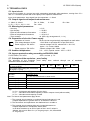
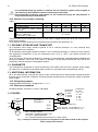
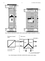
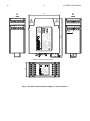
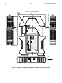
IO.ZS-30.31Ex.02(ENG) APLISENS MANUFACTURE OF PRESSURE TRANSMITTERS AND CONTROL INSTRUMENTS USER’S MANUAL REPEATER POWER SUPPLY (POWER SUPPLY – ISOLATOR) ZS–30Ex1 – with 24V DC supply ZS–31Ex1 – with 230V AC supply Ex version Edition A WARSAW OCTOBER 2012. APLISENS S.A. 03-192 Warszawa, ul. Morelowa 7 tel. +48 22 814 07 77; fax +48 22 814 07 78 www.aplisens.pl, e-mail: [email protected] A 1 IO.ZS-30.31Ex.02(ENG) Applied symbols Symbol i Description Warning that the instructions included in the documentation must be strictly observed in order to ensure the safety and full functionality of the device. Information particularly useful for installation and operation of equipment. Information particularly useful for installation and operation of Ex equipment. Information regarding the proceeding with used up equipment. BASIC REQUIREMENTS AND OPERATIONAL SAFETY - The manufacturer does not bear responsibility for any damages resulting from improper installation, not maintaining a proper technical condition and using for the purposes inconsistent with intended use of the device - Installation should be conducted by a qualified personnel, having the authorizations required for the installation of electrical intrinsically safe equipment. Personnel performing the installation is obliged to conduct it in accordance with this manual and with the regulations and standards regarding the intrinsical safety and electromagnetic compatibility applicable for the type of conducted installation. - In case when the device is out of order, it should be disconnected and returned to the manufacturer or an entity authorized by it for repair. In order to minimize the possibility of failures and hazards resulting for the personnel, the devices should be installed and used in environments safe in explosion respect, dry, and free from dusts and aggressive gases. - protect from mechanical strokes, excessive shocks and vibrations. - protect from excessive temperature variations. ZS-30Ex1 and ZS-31Ex1 repeater power supply should be installed only in safe zones. The lines to the hazardous zone should be made with particular care, observing the standards and regulations regarding such installations and observing the conditions of using. Table of contents 1. INTRODUCTION. ........................................................................................................................ 2 2. LIST OF USER SET.................................................................................................................... 2 3. APPLICATION OF ZS–30EX1 AND ZS–31EX1 REPEATER POWER SUPPLY ........................ 2 4. DESIGNATIONS ......................................................................................................................... 2 5. TECHNICAL DATA..................................................................................................................... 3 6. PRINCIPLE OF OPERATION. CONSTRUCTION ....................................................................... 4 7. PLACE FOR REPEATER POWER SUPPLY INSTALLATION. .................................................. 5 8. ASSEMBLY AND CONNECTIONS ............................................................................................ 5 9. SETTING AND ADJUSTMENT ................................................................................................... 6 10. INSPECTIONS, REPAIRS AND SPARE PARTS...................................................................... 6 11. PACKING, STORAGE AND TRANSPORT............................................................................... 7 12. GUARANTEE ........................................................................................................................... 7 13. ADDITIONAL INFORMATION .................................................................................................. 7 14. FIGURES .................................................................................................................................. 7 A 2 IO.ZS-30.31Ex.02(ENG) 1. INTRODUCTION. This manual is a document for the users of ZS–30Ex1 and ZS–31Ex1 repeater power supply, including basic technical data and instructions necessary to become familiar with their operation principle and the ways of operating. This manual includes also necessary instructions concerning the installation and operation as well as the proceeding in case of failures. This manual regards the repeater power supply in anti-explosive, intrinsically safe version. 2. LIST OF USER SET Power supplies are delivered in single and/or multiple packs. Every supply is delivered together with a “Product Certificate” which also is a guarantee card. A batch of transmitters is supplied together with the User’s Manual IO.ZS-30.31Ex.02(ENG) On a customer’s request, a “Declaration of Compliance” and/or appropriate certificate will be supplied. Two last documents can be found at www.aplisens.pl. 3. APPLICATION OF ZS–30Ex1 AND ZS–31Ex1 REPEATER POWER SUPPLY 3.1. ZS–30Ex1 and ZS–31Ex1 repeater power supply are the accompanying devices intended for the cooperation with two-wire transducers installed in explosion-hazard zones, supplied from one of abovementioned supplier and forming 4...20 mA transmission signal on the line. They supply the measuring circuit of transducers (called the ”input circuit”) with the voltage of nominal value from 15 to 25V, they receive the transmission signal 4...20 mA from transducers and they convert it into one of unified output signals. Input, output and supply circuits are galvanically separated. It ensures a galvanic separation of the transducer installed on the object in explosion-hazard zone from devices operating in the safe zone, such as: controllers, indicators, data collecting systems, etc. The application of isolator reduces the influence of interferences on operation of these devices and facilitates the configuration of measuring systems. 3.2. ZS–30Ex1 and ZS–31Ex1 repeater power supply are mounted in strip enclosures. ZS–30Ex1 is supplied by 24V DC and ZS–31Ex1 is supplied by 230V 50Hz. The supplies should be installed in closed cabinets or enclosures, in dry environments free from dusts and aggressive gases. Repeater power supply are intended for installation exclusively in safe zones. If the power supplier is installed in a hazard zone it can result in explosion or fire. 3.3. Intrinsically safe input circuit can cooperate with intrinsically safe circuit of the device (transmitter) installed in explosion-hazard zone, in accordance with the their conditions of using. Output circuit and the circuit supplying ZS–30Ex1 repeater power supply can cooperate with supply and measuring devices supplied by transformers from network with rated voltage of 230VAC. 4. DESIGNATIONS 4.1. Designations for anti-explosive versions i Each ZS–30Ex1 and ZS–31Ex1 repeater power supply is equipped with a rating plates which must include at least the following data: manufacturer’s name, CE mark, designation of type (ZS–30Ex1 or ZS–31Ex1), product name, factory number, value of input and output signals , mark of anti-explosive construction, designation of certificate: II(1) G [Ex ia Ga] IIC, I (M1) [Ex ia Ma] I, KDB 05ATEX 082 value of voltage, current and power of matching of intrinsically safe input circuit supply and allowed capacity and inductance of the input circuit. Input of intrinsically safe circuit is marked with blue color. 4.2. Marking method at ordering and manufacturing versions The way of marking at ordering and the producer versions in accordance with the current catalogue or ”Information Cards”. A 3 IO.ZS-30.31Ex.02(ENG) 5. TECHNICAL DATA 5.1. Input circuit Input circuit consists of a current loop with cooperating intrinsically safe transducer, coming from <P+> and <P–> terminals (marked with a blue plate) to the explosion-hazard zone. Input circuit parameters: Input signal from the transmitter: 4...20mA 5.2. Output signals and output load resistances: 4....20mA, 0...20mA 0...5V, 1...5V, 0...10V, 2...10V Ro 0...500, Ro 10k Ro 2k 0...5mA 5.3. Metrological parameters: 0,1% 0,05% 0,05% 0,01%/C ok. 0,05 s (by arrangement: 0,1 ÷ 1s) - Accuracy - Non-linearity - Effect of load resistance fluctuations - Effect of temperature fluctuations. - Time constant 5.4. Separation of circuits. Power supply Separation of circuits Test voltage between circuits Power supply of ZS–30Ex1 i all the circuits are galvanically separated from each other 1.5kV 50Hz or equivalent DC as per EN 61010-1 -nominal voltage 24V DC, allowed 24V 10% DC, ripple 1%, current 100mA -network voltage 230V 50Hz 10% Power supply of ZS–31Ex1 5.5. Ambient temperature 5C +55C, special version: -25°C÷ + 55°C. 5.6. Ingress protection rating according to EN 60529:2003 For ZS–30Ex1, ZS–31Ex1 -IP20 and see p. 7.2. 5.7. Principles of the explosion - proof safety The principles of the explosion EN60079-0:2009, EN60079-11:2012. proof Input circuit supply voltage UIN with one of the nominal values Input voltage after loading with a transmitter with signal 4...20 mA safety 15V were realized 18V through 20V use 22V of 25V UIN20 = UWE[V] x 0,75 Parameters Intrinsic safety Option 1 (25V) Terminals: P+ PIo = 100 mA, Characteristic of linear circuit. Uo = 25,5V Po = 0,63W Lo=2,2 mH Co=0,09 F Option 2 (22V) Uo = 23,1V Po = 0,56W Lo=2,2 mH Co = 0,13 F Option 3 (20V) Uo = 21,0V Po = 0,5W Lo=2,2 mH Co=0,175 F Option 4 (18V) Uo = 18,4V Uo = 15,75V Po = 0,41W Po = 0,4W Lo=2,2 mH Lo=2,2 mH Co = 0,27 F Co=0,45F ZS-30Ex ZS-31Ex Option 5 (15V) Sign: Lo, Co – Inductance and capacity of input circuit Li, Ci – Inductance and internal capacity of load in outputs circuit (without cable) Lc, Cc – Inductance and capacity of cable Note: The above load parameters apply where: 1. The external circuit contains no combined lumped inductance Li and lumped capacitance Ci greater than 1% of the above values or 2. The dinuctance and capacitance are distributed as in a cable or 3. The external circuit contains either only lumped inductance or lumped capacitance in combination with a cable. In all other situations up to 50% of each of the L and C values is allowed, but no more than Co=1 μF for gas groups I, IIA, IIB and 600 nF for group IIC. standards: A 4 IO.ZS-30.31Ex.02(ENG) 6. PRINCIPLE OF OPERATION. CONSTRUCTION 6.1. Electronic system The electronic system of ZS–30Ex1 and ZS–31Ex1 repeater power supply consists of 3 following circuits separated from each other (block diagram of the electronic system is shown on fig. 3): a. Supply circuit: - ZS–30Ex1: the main functional units of the supply circuit include a protective system, stabilizer and converter. This circuit is supplied with the nominal voltage 24V DC and it provides galvanically separated voltages for supply of input and output circuits. Supply circuit is protected against the exceeding of permissible voltage (24V ± 10%) and polarity changes by protective circuit. This system consists of 3 tyristors connected in parallel, which are initiated from two points: power supply input and output of the stabilizer supplying the converter; when the values of allowed voltage are exceeded. Moreover the system is equipped with a fuse, which disconnects the supply system. - ZS–31Ex1: the supply circuit is adapted to network supply 230V 50Hz. Two network transformers are applied, which supply separately the part of repeater power supply system including the input to the hazard zone and the circuit of output signals to the safe zone. The system of input to the hazard zone and the output system are supplied by specially designed and manufactured transformers. The coil forms are equipped with appropriately selected insulating barriers. The transformers are resistant to shorting in secondary circuit and they are equipped with thermic fuses (100C) protecting against excessive heating in case of intra-coil shorting. Transformers and the thermic fuses are encapsulated with hardenable epoxide or epoxide-polyurethane resin. b. Input system The input system can provide the voltage with on of the five nominal values: from 15V to 25V, in order to supply the transducer installed in explosion-hazard zone through a two-wire line. The 4÷20mA signal, which is forced on the line by the transducer, is introduced to the amplifier of separator input system and then it is sent, through an optoisolator, to the output circuit. The input circuit is equipped with a protective system limiting the short-circuit current and input voltage to the hazard zone. This system consists of a serial current limiter, containing durable resistors and 3 Zener diodes, connected in parallel, for voltage limiting. Nominal voltage can be 15V, 18V, 20V, 22V and 25V. The elements of this system are encapsulated with epoxide or epoxide-polyuethane resin, they are placed in enclosure made of insulating material and they form a kind of barrier designated as ”BEx”. c. Output circuit The output circuit converts the signal from the input circuit into one of a standard output signals. From the output circuit side the repeater power supply can cooperate with devices supplied by network transformers, from the network with nominal voltage of 230V, 50Hz. The output circuit is protected with TVS or Zener diodes and PTC thermistor. 6.2. Construction The electronic system of ZS–30Ex1 is mounted on the boards placed in a strip enclosure (fig. 5.) and in case of ZS–31Ex1 in the enclosure shown on fig. 4. A rating plate as well as information plates are placed on each enclosure. On the front panel there is a LED signaling that supply voltage is connected, and inside of 2 openings there are the knobs for zero and range corrections. The knobs are accessible from outside. The enclosures are adapted to be installed on T–35 or T–32 strips. i The terminals for connection of intrinsically safe input circuit are marked with a blue plate. A 5 IO.ZS-30.31Ex.02(ENG) 7. PLACE FOR REPEATER POWER SUPPLY INSTALLATION. i i 7.1. ZS–30Ex1 and ZS–31Ex1 repeater power supply in strip enclosures must be installed in explosive-safe, dry, free from dusts and aggressive gases places and they should be protected from mechanical hazards. They are designed for installation on strips (T–35 or T–32) and they require the cabinets or enclosures with locks, preventing the access of unauthorized persons. 7.2. If the place of installation does not meet the environment conditions specified in point 7.1, then the enclosure or installation cabinet must have the protection class of at least IP54 or higher, depending on specific conditions. Similarly it is recommended to use additional enclosures or cabinets with increased protection class in case when it is predicted that the devices will operate at minus ambient temperatures. 7.3. In case when wall-enclosures are used, then the enclosure containing one or several isolators installed on T–35 or T–32 strip has the same status as installation cabinet, i.e. it is a place of intrinsically safe devices installation (repeater power supply in this case). 8. ASSEMBLY AND CONNECTIONS 8.1. ZS–30Ex1 and ZS–31Ex1 repeater power supply should be installed in vertical position, in accordance with front panel position – ventilating openings should be at the top and the bottom of power supplies. There should be a free space left over, under and between the power supplies, allowing them to be cooled by circulating air (see fig. 2). 8.2. ZS–30Ex1 and ZS–31Ex1 repeater power supply should be connected in accordance with fig. 3. Only the circuits of intrinsically safe devices (e.g. converters) of ”ia” and ”ib” categories, not having internal sources of power supply, can be connected to <P+> and <P–> input terminals, which are marked with a blue plate. Supply and measuring line to the hazard zone (input circuit) is made of A or B conductor, in accordance with EN 50039 (see point 8.5). Maximal values of circuit inductance and capacity, which are specified in the certificate (see point 5.1) cannot be exceeded. It is recommended to lead the signal lines with ”twisted pair” cable, and in case of big electromagnetic interferences the ”twisted pair” cables should be shielded additionally. It should be avoided putting the signal cables along to other interfering cables, e.g. in the vicinity of big energy receivers or along with feeding and inductive load cables. 8.3. The cooperating devices, located in the safe zone and supplied with maximal voltage of 250 VAC through a network transformer can be connected to <0+> and <0–> terminals of ZS–30Ex1 and ZS–31Ex1 output circuits. 8.4. In case when ZS–30Ex1 and ZS–31Ex1 devices are mounted on strips, both in cabinets and wall-enclosures, a distance of minimum 50 mm between the terminals of intrinsically safe and non-intrinsically safe circuits must be kept. If such a distance is not kept, then an insulating or metal, grounded barrier should be applied. An additional fixing of installation conductors in the vicinity of terminals is recommended. 8.5. Adjacent installations and devices should be mounted in a way not violating the conditions of separation between intrinsically safe and non-intrinsically safe circuits (appropriate distances, barriers, additional cable fixings, insulation status, etc.). The inscriptions informing about the contents and place when the cables are led out should be placed on cabinets and enclosures. 8.6. In case of ZS–30Ex1, if the influence of electric surges is expected from the side of 24V supply (e.g. in case of big distance from 24 V power supply to the separator), then it is recommended to equip the 24V supply line with overvoltage protection. i 8.7. From 230 V power supply side the cabling of ZS–31Ex1 device must be in accordance with applicable standards regarding the safety and electromagnetic compatibility as well as with local rules and regulations. In case of interferences from 230V supply it is recommended to apply anti-interference filters. The cables connected to the filter output cannot be placed nearest to the interfered cables (e.g. relays or contactors controlling circuits). 8.8. Basic requirements specified in EN 50039 standard for A and B type cables applied in supply and measuring circuits in hazard zone. A 6 IO.ZS-30.31Ex.02(ENG) 8.8.1. Insulation thickness of the cables should be adapted to the material type, but not smaller than 0.2mm. Strength of cable insulation: – 2UN, but not less than 500V AC per conductor – 500V AC between cable shield and connected strands – 1000VAC between two group of strands, each containing half of connected strands. i 8.8.2. No non-intrinsically safe circuit can be run in a multi-strands cable. The strands from circuits in maximal voltage exceeding 60 V should not be run in the one cable. 8.8.3. Cables should be protected against damages by placing them, for example, in cable trays, protective tubes, cable racks or by application of solid fixings, etc. 9. SETTING AND ADJUSTMENT The following parameters of ZS–30Ex1 and ZS–31Ex1 repeater power supply are factory setting (according to customer’s requirements): supply voltage of input circuit , time constant and one of output signals specified in technical data. The user can only make correction of the beginning and width of the range. There are 2 openings on the enclosure front panel, allowing to access the potentiometers’ knobs, marked as ”zero” and ”range”. The corrections of ”zero-range” settings can be make e.g. as it is shown on fig.1. 10. INSPECTIONS, REPAIRS AND SPARE PARTS 10.1. Periodic inspections. i i 10.1.1. During normal operation ZS–30Ex1 and ZS–31Ex1 repeater power supply do not require any maintenance operations and the inspections should be conducted periodically, in accordance with the requirements specified in control standards applicable for users of anti-explosive equipment. External condition of device should be checked during an inspection. The following should be checked: - if there are no traces of mechanical damages, - the fixings of cable connections and terminals have not been loosen, - rating and other plates are not damaged and legible. 10.1.2. Check the value of short-circuit current of input circuit, connecting a milliammeter to <P+>, <P–> terminals and reading the indication. The value of short-circuit current should not exceed the values given in table 1. Checking and correction of characteristics settings should be conducted e.g. as it is shown on fig.1. Check the value of voltage supplying the converter in hazard zone, connecting the voltmeter to <P+> and <P–> terminals. The indications should be in accordance with the values given in Table 1. 10.2. Non-periodical inspections Non-periodical inspections are conducted when the isolators could be subjected to harmful mechanical or electrical hazards or in cases when any abnormalities in device operation are detected. 10.2.1. Some typical symptoms of inefficiency a) It applies to ZS-30Ex1 - Signal LED on the front panel is not lit, no signal input (terminals P +, P-) and output (terminals 0 +, 0 -) and the terminal voltage (V +, V-) voltage 24VDC ± 10%. Such failures usually means damage to the power circuit fuse (fuse pipe, glass or ceramic Ø5x20, In = 250mA, Un = 250V, fast, compatible with IEC60127 or equivalent standard). Fuse exchange is permissible by the service user. Access to the fuse is after the sliding of the part housing and removing of the fuse cover. These activities can be made after switched off a supply voltage - If the LED is lit and the lack of input and output signals- the assessment of disability and its repair can do the manufacturer or an entity authorized by him only. b) It applies to ZS-31Ex1 In case of inefficacy with symptoms as in p. a), the assessment of damage and repairs can be doing only by the manufacturer or entity authorized by the manufacturer. 10.3. If any abnormalities are detected in the functioning of the measuring system containing the repeater power supply, then also the other elements of the circuit, such as: transducer, signal lines, and eventually the characteristics of repeater power supply should be checked. Improper relations between the input and output signals (characteristics error) can indicate that the converting system is damaged. A 7 IO.ZS-30.31Ex.02(ENG) It is prohibited doing any repairs or interfere into the electronic system of the supplier in case when any abnormalities in device functioning are detected. The assessment of damage and repairs can be conducted only by the manufacturer or entity authorized by the manufacturer. 10.4. Data for circuit status checking Table 1. 1 i Supply voltage to the hazard zone 15V 18V 20V – nominal values – limit values at output current 14,715,75V 17,618,4V 19,521V 2 „0” mA Input circuit shorting current (<P+> 24 28 mA 3 and <P– > terminals) for ZS–30Ex1 and ZS–31Ex1 22V 25V 21,523,1V 24,525,5V Values of short-circuit current given in line 3 of the Table 1 regard the situation when the internal current limiter works properly. Limit values of current resulting from intrinsical safety conditions are specified in 5.1. 11. PACKING, STORAGE AND TRANSPORT 11.1. Repeater power supply should be packed in unit or collective packages, in a way protecting them against damages during transport. 11.2. Repeater power supply should be stored in unit or collective packages, in rooms free from vapours and aggressive substances, at the air temperature from +5°C to +40°C, and relative humidity not exceeding 85%. 11.3. The devices should be transported in collective or unit packages, protected against displacement during the transport. Land, sea or air means of transport can be used provided that they ensure the elimination of direct influence of atmospheric factors. 12. GUARANTEE The manufacturer guarantees a correct functioning of ZS–30Ex1 and ZS–31Ex1 repeater power supply for a period of 12 months from purchase date, as well as a guarantee and post-guarantee service. 13. ADDITIONAL INFORMATION 13.1. The manufacturer reserves the right to make constructional and technological changes provided that they do not violate the conditions of intrinsical safety certificate and not impair the quality of repeater power supply. 13.2. Related documents Certificate KDB 05ATEX082 + Supplement n 1, 2, 3. 13.3. Reference standards EN 60079-0:2009, EN 60079-11:2012, EN 60529 14. FIGURES 4...20mA PS VC2 VC2 P+ Input circuit RW1 0+ RW2 Connection of VC2 <0+>,<0->. 0...10V 0...5V 1...5V 2...10V 0- (L)V+ P- VC1 ZS-30Ex1, ZS-31Ex1 Connection as per fig. 0...5mA 0...20mA 4...20mA (N)V- RD1=590 max. Supply 24V DC for ZS-30Ex1 (V+, V-) Supply 230V AC for ZS-31Ex1 (L, N) RD1 - Decade resistors, RW1,RW2 – Standard resistors 10 VC1,VC2 – Digital voltmeters PS – System simulating the transducers or settle resistor. Fig. 1. Example of measuring system for assignment of ZS–30Ex1 and ZS–31Ex1 repeater power supply characteristics A 8 IO.ZS-30.31Ex.02(ENG) min.50 min.5 DC PLY + V V SUPPLY _ 24V DC min.50 min.5 + O _ OUTPUT O 4...20mA + O ZS30Ex1 ZS30Ex 1453 I (M1) [Ex ia Ma] I II (1)G [Ex ia Ga] IIC KDB 05ATEX... II I K span sp zero z I (M1) [Ex ia Ma] I II (1)G [Ex ia Ga] IIC KDB 05ATEX 082 IP20 Serial number: .................... Rep ZS- Serial number:............ YEAR:.......................... Seria YEA zero + P min.50 _ INPUT P 4...20mA min.50 + P Repeater power supply span ZS-31 Ex1 Fig.2. Distances of ZS–30Ex1 and ZS–31Ex1 repeater power supplies installation in cabinet Explosion hazard zone Safe zone Output signals acc. to point. 5.2. Marked with blue colour 4...20mA P+ 0+ Input PIntrinsically safe transmitter Output 0- Supply V+(L) V-(N) <V+>, <V-> 24V DC for ZS-30Ex1 <L, N> 230V AC for ZS-31Ex1 Fig. 3. Block diagram of ZS–30Ex1 and ZS–31Ex1 repeater power supply. Serial number......... YEAR:.................. Zero Supply N L Output O+ O- B 106,7 Temperature measuring range: 5...55°C IP20 Input Uo L, N Power supply: 230 V AC YEAR ........... 4...20mA O+,O- Output : P+ PSerial number:................... To transmitter 4...20 mA in hazard area Ex I (M1) [Ex ia Ma] I Parameters of the input circuit : II (1)G [Ex ia Ga] IIC Po= Io= Uo= KDB 05ATEX 082 Lo= Co= MOUNT IN SAFE AREA ONLY www.aplisens.pl REPEATER POWER SUPPLY TYPE: ZS-31Ex1 A Repeater power supply type ZS-31Ex1 Span 1453 L O I (M1) [Ex ia Ma] I II (1)G [Ex ia Ga] IIC KDB 05ATEX 082 Supply 230V AC + O 1453 03-192 WARSZAW Str. Morelowa 7 tel. +48 022 814 07 77 fax +48 022 814 07 78 POLAND Input 4...20mA 40 A 9 IO.ZS-30.31Ex.02(ENG) 79 B _ A N Input 4...20mA blue colour Holder for TS-35 and TS-32 strips Fig. 4. ZS–31Ex1 repeater power supply in a strip enclosure. P _ + P Supply 24V DC _ INPUT P 4...20mA .................... IP20 Serial number zero span Supply Output V+ V- O+ O- 03-192 WARSZAW Str. Morelowa 7 tel. +48 022 814 07 77 fax +48 022 814 07 78 POLAND Temperature measuring range: 5...55°C IP20 Input Uo V+,V- Power supply 24 V DC (max 28V) Rok prod......................... O+,O- Output .................. P+ PSerial number:...................... To transmitter 4...20 mA in hazard area Ex I (M1) [Ex ia Ma] I Parameters of the input circuit : II (1)G [Ex ia Ga] IIC Po= Io= Uo= KDB Nr 05ATEX... Lo= Co= MOUNT IN SAFE AREA ONLY www.aplisens.pl 1453 10 + P 1453 OUTPUT 4...20mA A I (M1) [Ex ia Ma] I II (1)G [Ex ia Ga] IIC KDB 05ATEX082 ZS30Ex1 0 _ _ V + 0 115 B 250 mA / IEC 127 + V 22,5 A IO.ZS-30.31Ex.02(ENG) Before sliding off a part of housing, press the snaps located on the sideway surfaces Fuse 99 B A blue colour Fig. 5. ZS–30Ex1 repeater power supply assembled in a strip enclosure.


![[17] User`s Manual ver. 2.0.2](http://vs1.manualzilla.com/store/data/005765389_1-e376d351ef2708f30fcfdc5f98b9ba18-150x150.png)