1
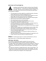
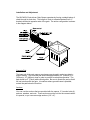
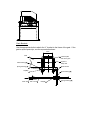
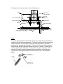
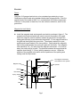
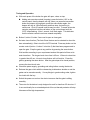
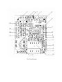
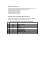
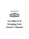
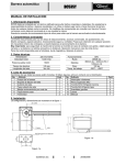
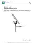
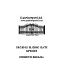
SKC400U SLIDING GATE
OPENER
OWNER’S MANUAL
IMPORTANT SAFTEY INFORMATION
Installing the SKC400U Gate Opener requires wiring of standard
110V electrical lines. This should only be performed by a trained
technician. Mis-wiring could cause personal injury or DEATH. To
prevent the risk of electrocution, be sure to turn off all power to the SKC400U
until installation is complete.
•
•
•
•
•
•
•
•
•
•
•
•
•
•
The gate opener should be installed by a qualified technician; otherwise,
serious personal injury or property damage may occur
The auto-reverse function must be checked during installation to ensure
that the gate can auto-reverse in the event of obstruction
Children should not be allowed to play near or operate automatic gates.
Read the entire manual before starting installation.
The automatic gate opener must be grounded.
Do not attempt to go through the gate while it is still in motion.
This operator is intended for vehicular use only.
Install the gate opener on the inside of the propert y, DO NOT install it on
the outside of the property where the public has access to it.
Be careful when in close proximity to moving parts where hands or fingers
could be pinched.
Additional safety equipment such as photoelectric sensors, safety edges,
roller guards and warning signs must be installed to prevent injury.
Do n ot allow control devices to be placed so that a person can access
them by reaching through the gate.
In the event of power failure, an emergency release key allows you to
operate the gate manually.
The opener should be switched off before repairing it or opening its cover.
Please erase and reset the code after installing the opener.
Class I: A vehicular gate opener (or system) intended solely for use in a
single-family home, or an associated garage or parking area.
ADDITIONAL FEATURES
• An interface for an optional keypad is available on the control board.
• User may add additional remote controllers to operate the gate opener.
• This gate opener includes emergency stop and reverse functions if it senses an
obstruction. This feature MUST be tuned prior to operation. Be sure to follow
the directions in the section on Tuning the Auto Reverse prior to operational
use.
• The device is composed of a single-phase motor, worm, and worm gear. The
main shaft of the motor rotates the worm with the clutch engaged. The worm
rotates the worm gear and output sprocket wheel, which drives the chain and
pushes the bracket (fixed to the gate), thus moving the gate.
Specifications
Power Supply
AC 110V± 10%V, 60Hz
Motor Speed
1470 rpm
Starting Current
<8A
Gate Moving Speed
10m/min
Opening Strength
>400N
Auto -Close-Time
0 ~ 45 sec.
Remote Control Mode
Single Button
Environmental Temperature
-25C ~ 50C
Net Weight
21 Kg
Emergency Release Key in Case of Power Failure
Parts List
•
•
•
•
•
•
•
•
•
•
•
•
•
•
•
•
•
(1) Sliding gate operator
(1) Operator Base
(1) Limit switch sensor
(2) Remote control
(2) Master Links
(1) 10 ft. Chain
(2) Chain Bolts
(2) Chain Brackets
(4) “U” Bolts for 2_ (51mm) for square & round gate frame
(4) 2 ¾ _ (70mm) #48 Bolts for mounting operator to the base and washers
(4) 2 ½ _ (64mm) Bolts for mounting Magnet brackets and washers
(4) 3 ¾ _Anchor bolts, Anchors, Washers and Nuts (In the same bag with Manual
release key)
(4) 5/8_ (15mm) Socket H ead Cap screws for mounting chain box
(2) Manual release key
(2) Magnet brackets
(2) Magnets
Installation and Safety manual
Installation and Adjustment
The SKC400U Chain-driven Gate Opener operates by forcing a straight piece of
chain through its chain box. This length of chain is extended between two “L”
brackets located at opposite ends of the gate. The entire configuration is shown
in the diagram below.
Concrete Pad
The base unit of the gate opener requires a concrete pad in order to maintain
proper stability. The concrete pad should be approximately 24” (600mm) x 12”
(300mm) x 18” (460mm) deep in order to provide for adequate operation. The
pad should be 3” (70mm) above finish grade. Be sure to locate the pad so that it
will not interfere with the gate. In locations where ground freeze is possible,
extend the pad below the frost line.
Anchors
You can use the anchors that are provided with the opener, 3 ¾ anchor bolts (4),
anchors, washers, and nuts. These anchors must be set into the concrete when
it is poured, or you can use wedge anchors (1/4” x 4”).
Gate operator
Nut
U shape steel
Support bracket
Cable
Bolt
Operator Base
Mount the gate opener base to the concrete pad. The distance between the gate
and the base should be no more than 2 ½ “ (64mm). Verify that the opener is
leveled properly.
Chain Box
Make sure the ends of the guide chain are out of the chain holes on both sides of
the chain box. Remove the cover and insert the manual release key and turn
counter-clockwise to disengage the clutch. Remove the tape from the shaft and
line up the key on the shaft with the sprocket at the chain box. Insert the
sprocket from the chain box into the operator shaft. Place the operator on top of
the base and use (4) 5/8 “ (15mm) socket head cap screws to mount the chain
box in to the base.
Opener
Mount the gate opener to the base using (4) 2 ¾ “ (70mm) #48 bolts and washers.
Make sure there is no more than 1/8” (2mm) of space between the cover and the
chain box. Check the opener and make sure it is lined up with the gate.
Chain Brackets
Use the appropriate bolts to attach the “L” bracket to the frame of the gate. If the
gate is square post style, use the square bolts shown.
2inch
Gate
2''steel square
cube of the gate
Plain washer(§ 6
¶)
Square U
shape bolt
Spring washer(§ 6
¶)
Bend bracket
Nut(M6)
Chain link
Plain washer(§ 8
¶)
Adjustment
bolt of chain
Nut(M8)
Spring washer(§ 8
¶)
If the gate is of round post style, use the U bolts shown.
2inch
Gate
2''steel round
cube of the gate
Plain washer(§ 6
¶)
Round U
shape bolt
Spring washer(§ 6
¶)
Bend bracket
Nut(M6)
Chain link
Plain washer(§ 8
¶)
Adjustment
bolt of chain
Nut(M8)
Spring washer(§ 8
¶)
Chain
Close the gate and attach a chain bolt to the piece of chain that comes with the
chain box using enclosure master links. Tighten the chain bolt to the bracket with
washers and nuts. Pull the chain through the chain wheel box to the other “L”
bracket at the opposite end of the gate. Connect the other end of the chain and
the chain bolt, and then tighten the chain bolt to the “L” bracket. Thread up the
chain by adjusting the chain bolt. Cut the chain to length if necessary. Make
sure that the chain is perfectly aligned with the chain holes on the chain box.
Tighten the chain by tightening the chain bolts at either end. See illustration
below.
Electrical
Power
Using the 18-3 gauge electrical wire, wire a standard grounded plug to your
Gatekeeper control board using standard electricians wiring practices. Wire the
opposite end of this cable to the E, N, L contacts (block 20) of the control board.
Connect L to the power or black line, N to the neutral or white line, and E to the
ground line.
Magnets for Limit Switch
l Install the magnetic steel and magnetic reed switch as shown in figure 6. The
magnetic steel and reed switch are used to control the position of the gate.
When the magnetic steel is installed, release the gear clutch and push the
sliding gate manually to pre-determine the position. Fit the magnet bracket to
the gate and then tighten the gear clutch. The shorter bracket is for open
position and longer bracket is for close position. Finally adjust the magnetic
steel to the proper position by moving the gate with the motor. The magnetic
steel should be .39 - .59 “away from the magnetic reed switch. If it is too far
away, the switch will fail to work. The distance between the magnet and the
operator should be @ ½” (12mm) with the operator cover on. Adjust the
position of the magnetic reed switch until the positions of the opening and
closing meet the requirement.
10-15mm
The magnetic reed switch
was installed in the operator.
Magnetic steel
Plain washer
214.5mm
Bracket
Gate operator
Spring washer
Bolt
Nut
Nut
Gate
Fig.6
Tuning and Operation
l With each press of the button the gate will open, close, or stop.
n
Adding extra remote controls (learning): press the button “AN” on the
control board, then the beeper will ring, when you press the transmitter
button the beeper will ring again, press the same button again, the
beeper will ring at 1/2Hz frequency and then stop, the last ring is
continuous. Up to 25 remote controls may be used. To erase all remote
controls, press and hold the red button on the control board until the
“LED” stops flashing. After 1 second, it will flash again. This indicates
that the remote controls have been erased completely.
l Button 1,button 2, button 3 are used to open or close gate.
l Set auto close function (The Auto-Close feature can be selected to close the
door automatically) : Short -circuit the AUTO terminal. Press any button on the
remote control (button 1, button 2 or button 3) that has been programmed to
open the gate. S top the gate at any position by pressing the same button.
Wait a while according to your requirement and set this period of time as its
auto-close time. The longest auto close time is 45 sec. If the auto close time
is greater than 45 sec., the auto close feature will not function. C lose the
gate by pressing the same button. After the gate stops at its closed position,
remove the short-circuit wire.
l Check the power supply, grounding and wiring before running the device.
l Release the gear clutch with the release key to determine whether or not the
gates can be moved manually. If everything is in good working order, tighten
the clutch with the key.
l Switch the power on and run the device to ensure that the gate is sliding
smoothly.
l The motor for the device is only designed to work for less than 25 minutes. If
it runs continually for an extended period of time, a thermal protector will stop
it because of the high temperature.
Obstruction Sensor
The Obstruction Sensor continuously monitors the gate movement for any
obstructions. If any obstructions are detected when the gate is closing, the gate
will stop and reverse back to the open position. . If any obstructions are detected
when opening, the gate will stop. The factory setting is set at MEDIUM
sensitivity. You may need to increase or decrease depending on the weight and
the condition of your gate.
Adjustment of the Auto-Reverse Function
l Tuning the auto-reverse safety function: Rotate the “Force Adj. (VR1)” Knob
with a screwdriver. The resistance may be increased or decreased by
rotating clockwise or counterclockwise. If you turn the overload variable
resistors clockwise it will increase sensitivity. If you turn the overload variable
resistors counterclockwise, it will decrease sensitivity. NOTE: If the gate fails
to reverse in the event of obstruction, then the opening force or closing force
should be checked for conformity with requirements and adjusted
accordingly. The gate will reverse if obstructed when closing, and will stop if
jammed when opening. Exchange wires V and W if the auto-reverse
direction is wrong. Exchange wires OP and CL if the limit direction is wrong.
WARNING: Do not attempt to tune the gate by placing your hand, arm or other
body part in the path of the gate, as serious injury could result. Damage to the
gate opener motors may also occur by placing a heavy immovable object in the
path during the testing phase. Instead, place a light object in the path (e.g., a
chair or trash can) which can be pushed out of the way without causing damage
to the gate motors, if the setting is still too high. Note : This auto reverse function
should be regularly inspected and adjusted if necessary. Once the tuning is
complete you may replace the cover.
Fig.7 Control board
Wiring Notes of Control Board
1. Power Switch: ON/OFF
2. Fuse: 10A, Ø5x20 glass tube
3. Antenna: ANT
4. Buzzer: DC12V
5. Memory Card: 93C66
6. CPU: PIC16C57C
7. Button Switch: single button K, GND
8.
K N.O.
GND
9. Limit Switch: CL (Down), CO (Com), OP (Up)
CL
CO N.C.
OP
10. Output Power Supply: DC12V+ (+DC12V), COM- (GND)
11. Infrared: I.R. (N.C)
12. Output Power Supply: AC24V
13. Power Indicator: LED
14. Learn Button: LEARN
15. Force Adjustor: Clockwise +, Counterclockwise –
16. Transformer: 110V/12Vx2
17. Sampling Transformer: 120V/8.8V 4W
18. Alarm Lamp: AC110V
19. Motor Capacitor: 55µF 300V AC
20. Motor: U (Com), V (Positive direction), W (Opposite Direction)
21. Power Input: E (Earth), L (Line), N (Neutral) AC110V
Maintenance and Electrical
Every six months check the following items for proper operation of the unit
• Check the chain lubricant and add 1# grease regularly.
• Lubricate shafts and sprockets.
• Keep opener clean at all times.
• Check and tighten anchors bolts.
• Check inside cover for insects.
Install the External Keypad/Button Switch (See Table 3)
The port “GND” is the common port, the port “K” is used to open the gate , “G”
is used to close the gate, and “T” is used to stop the gate .
Table 3: Wiring terminal for external button / external device
No.
Tag
1
2
3
4
5
6
7
8
9
12V
GND
IC
IR
LD
5V
K
G
T
Remark
Output +12V 100mA
Ground
N.O.
Infrared N.C .
Loop-detector interface
Output +5V 100mA
External button: Open
External button: Close
External button: Stop
TroubleShooting
This Sliding Gate Operator is wired to be mounted as right
hand installation.
GATE WILL NOT OPEN OR CLOSE
1) Make sure Power switch is ON
2) Check for AC power light
3) Check terminals connections at block 20 “110VAC” High power side of
control board
4) Check for limit switch Jumper 8 (N/O or N/C). Factory settings should be
N/O for the operator to work.
5) Check for any active inputs such as safety beams
6) Check fuse F1
7) Check clutch to make sure it is tight (use special key provided)
6) In case of Power Failure , use the manual release key to open or close
gate manually. Insert key and turn Counterclockwise to release the clutch.
After power is restored, use the manual release key to tighten the clutch by
turning the key Clockwise and resume normal operation.
GATE STARTS OPENING OR CLOSING THEN STOPS
1) Adjust Obstruction S ensor to decrease sensitivity (see section Obstruction
Sensor)
2) Make sure gate is moving freely; check wheels, roller guides and any
obstacles.
3) Check the tightness of the chain to make sure it is not too tight.
GATE DOES NOT STOP WHEN IT REACHES OPEN OR CLOSE POSITION
1) Check the position of the magnets.
2) Check that the light comes on when the gate is closed (upper magnet), and
when the gate is open (lower magnet)
3) Slide the gate manually to open and close positions and make sure the light
on the control board comes on when gate is in the open or close position.
REMOTE CONTROL DOES NOT WORK
1) Check receiver make sure the wire harness is plugged in at the receiver.
2) Check the dipswitch settings at the receiver and remote control to make
sure they are set at same p osition.
3) Check the batteries on your remote control.
GATE OPENS AUTOMATICALLY AFTER IT IS CLOSED
1) Check motor & limit switch wiring.
Gatekeeper Ltd.
P.O. Box 752
Laceys Spring, AL 35754
[email protected]
For updated versions of the manual see:
http://www.gatekeeperltd.com
© 2005-2007
GatekeeperLtd All Rights Reserved