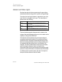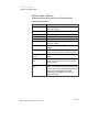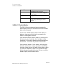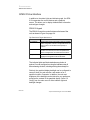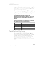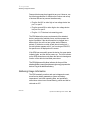
1
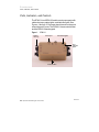
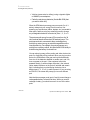
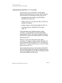
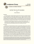
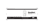
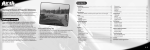
 Squad Power Manager (SPM)
User Guide
Document number 000-367
Revision 6
© 2010 Protonex Technology Corporation. All rights reserved.
Although this guide has been prepared with every precaution
to ensure accuracy, Protonex Technology Corporation
assumes no liability for any errors or omissions, nor for
any damages resulting from the application or use of
this information.
Patents pending.
Contents
Protonex
Chapter 1
Safety Warnings ................................................. 1-1
Chapter 2
Product Overview ............................................... 2-1
Ports, Indicators, and Controls............................... 2-2
Scavenger Ports (3 and 4) ..................................... 2-4
General Purpose Ports (1, 2, 5, and 6) ................... 2-6
Indicator and Status Lights .................................... 2-7
Indicator Lights—Batteries ................................. 2-8
Indicator Lights—Radios and Computers ........... 2-9
Indicator Lights—Solar and Fuel Cell. ................ 2-9
SPM-611 Control Button ................................... 2-10
SPM-612 User Interface .................................... 2-11
SPM-612 Keypad ............................................ 2-11
SPM-612 Graphical Display ............................. 2-12
Menu Overview ............................................... 2-14
Required Components ...................................... 2-15
Chapter 3
Getting Started ................................................... 3-1
Connecting a Battery ............................................. 3-1
Connecting a Radio or Computer ........................... 3-2
Connecting More Batteries or Devices ................... 3-2
Connecting a Power Source .................................. 3-2
Chapter 4
Using the SPM .................................................... 4-1
Charging the Batteries ........................................... 4-1
Powering Radios and Other Devices ..................... 4-2
Gathering Usage Information ................................. 4-3
Connecting a PC .................................................... 4-5
Upgrading Firmware ........................................... 4-6
Uploading Datalogs ............................................ 4-8
Real-Time Monitoring ...................................... 4-10
Squad Power Manager User Guide iii
Chapter 5
Protonex
Contact and Support Information ........................ 5-1
Telephone ........................................................ 5-1
E-Mail .............................................................. 5-1
Squad Power Manager User Guide iii
1 Safety Warnings
Chapter 1
Safety Warnings
The SPM-611 and SPM-612 power managers can be used with
high energy batteries and devices. Misuse of the power
managers or the attached devices can result in electrical
sparking and fire, in battery venting and fire, and in personal
injury or damage to the equipment.
To assure safe operation:
• Read this manual and all safety documentation for
batteries and equipment, and follow applicable safety
and usage guidelines.
• Do not charge batteries above or below their rated charge
temperatures.
• Do not open or modify the SPM power manager.
• Do not modify smart power cables.
• Connect smart power cables only to the devices for which
they are specified.
• Do not use worn or damaged power cables.
• Do not power modified or damaged equipment.
• Do not use SPM-611 or SPM-612 power managers to
charge batteries or battery systems which have not been
independently tested for safe operation across the
operating range being used.
Protonex
Squad Power Manager User Guide 1-1
1 Safety Warnings
1-2 Squad Power Manager User Guide
Protonex
2 Product Overview
Chapter 2
Product Overview
The Squad Power Manager (SPM) is a lightweight, compact
and rugged intelligent power management system. It supports
a host of power conversion and battery charging capabilities
for today’s warfighter, and is compatible with most
man-portable military batteries and battery-powered
equipment on the battlefield.
The Squad Power Manager enables a wide range of military
applications including the following:
• GSK field power
• Any suite of gear using multiple BA-5590 batteries
for power
• Land Warrior (LW) and Ground Soldier System (GSS)
• The Future Warrior Technology Integration (FWTI) platform
• Fuel cell, wind, and solar power sources
• Mission power usage profiling of man-portable gear
This manual applies to both the SPM-611 and the SPM-612
power managers. Differences in the power managers are
noted in the appropriate sections of this manual.
Protonex
Squad Power Manager User Guide 2-1
2
Product Overview
Ports, Indicators, and Controls
Ports, Indicators, and Controls
The SPM-611 and SPM-612 each have six power ports with
rubber dust caps, status lights, and indicator lights. See
Figures 1 through 3. Dust caps should remain on the ports
unless the port is in use. The SPM-611 has a control button
and the SPM-612 has a keypad.
Figure 1.
SPM-611
Rubber
dust cap
Power port
Port status lights
Port
indicator
lights
Control button
2-2 Squad Power Manager User Guide
Protonex
2
Product Overview
Ports, Indicators, and Controls
Figure 2.
Rubber
dust cap
SPM-612
Power port
Port status lights
Port
indicator
lights
Graphical
screen
Key pad
Protonex
Squad Power Manager User Guide 2-3
2
Product Overview
Scavenger Ports (3 and 4)
Figure 3 shows the keys on the SPM-612 keypad.
Figure 3.
SPM-612 Keypad
Escape
Down
Up
Enter
The power ports on the SPM-611 are the same as those on the
SPM-612. Each port is optimized for different functionality.
See “Scavenger Ports (3 and 4)” on page 2-4 and “General
Purpose Ports (1, 2, 5, and 6)” on page 2-6 for information on
each port.
Scavenger Ports (3 and 4)
Use ports 3 or 4 to actively pull energy into the system.
Examples of energy sources that should be connected to ports
3 or 4 include:
• Solar panels
• AC wall adapters
• Fuel cells
2-4 Squad Power Manager User Guide
Protonex
2
Product Overview
Scavenger Ports (3 and 4)
• Vehicles (commercial or military) using a cigarette lighter
or HMMWV power adapters
• Partially used primary batteries (like the BA-5590) that
you want to drain fully
When the SPM detects an energy source on ports 3 or 4, it
actively attempts to pull energy from this source, first
powering any load devices (radios, laptops, etc.) connected to
other ports, and then using any remaining power to charge
any rechargeable batteries connected to ports 1, 2, 5, or 6.
The ports can pull energy from any DC source from 4 to 34
volts, and can handle as much as 150 watts of power. The
ports sense what is connected to them, and adjust how
quickly they extract energy to match the capabilities of the
connected device. For example, the port pulls power very
quickly from a military vehicle, but drains a BA-5590 slowly to
avoid blowing the battery’s internal fuse.
You can also plug many military radios and other devices into
ports 3 or 4 and they will be powered. When you plug in such a
device, the SPM detects if the gear can be powered directly
from one of the batteries attached to another port, and if so,
turns on power to the port. If the equipment cannot be
powered directly (it needs voltage conversion), the red and
yellow status indicators on the port will activate and remain
solid, indicating that you should plug the device into a
different port (1, 2, 5, or 6) in order to power it. If you are using
an SPM-612, the screen will prompt you to use a different
port.
Note that the scavenger ports (ports 3 and 4) cannot charge a
rechargeable battery connected to them. When you need to
recharge a battery, you should connect it to one of the other
ports.
Protonex
Squad Power Manager User Guide 2-5
2
Product Overview
General Purpose Ports (1, 2, 5, and 6)
General Purpose Ports (1, 2, 5, and 6)
Use these ports for most connections to rechargeable
batteries and portable devices you want to power. Examples
of devices that you should plug into these ports include:
• Rechargeable military batteries, like the BB-2590,
BB-2557, Li-80, and Li-145
• Military radios, such as the PRC-148, PRC-119F, PRC-152,
and PRC-117F SatCom
• Laptop computers, including the Toughbook, MR-1, etc.
• Commercial devices, including GPS units, radios,
lights, etc.
These ports share a pair of battery chargers / voltage
converters—one shared by ports 1 and 2, and the other
shared by ports 5 and 6. If you want to charge two batteries
simultaneously, connect one of them to ports 1 or 2, and the
other to ports 5 or 6.
Similarly, if you have two devices that need voltage
conversion—for example, a laptop computer that needs 19V
and a commercial GPS that requires 12V, or a 24V radio like
the PRC-117F—connect one device to port 1 or port 2, and the
other device to port 5 or 6.
Most portable military devices, such as radios, military GPS
units, and military laptops, do not require voltage conversion,
and can be plugged into any port with no consideration to the
device that is plugged into other ports.
2-6 Squad Power Manager User Guide
Protonex
2 Product Overview
Indicator and Status Lights
Indicator and Status Lights
Each port has a level indicator graph using five green lights,
and a status indicator using a red, a yellow, and a green light.
The status that each light indicates is dependent upon what
type of device is plugged into the port. The status lights in
general mean the following:
Light
Description
Green
The port is in use and the attached device is in a
normal state.
Yellow
The port is in use and the attached device is in a
standby state.
Red
The port is disabled because an error has occurred.
The level indicator graph indicates levels in relation to the
ratings of the device attached to the port, not in relation to the
capacity or ratings of the SPM itself.
For batteries, the level indicator shows the percentage of
energy that remains in the battery. For energy sources and
powered devices, the graph indicates the percentage of the
device’s normal power capacity (for sources) or power need
(for load devices) that is going into or out of the port. For
example, if a radio is rated to draw a maximum of 25 watts,
and it is presently drawing 5 watts, one light will be
illuminated. When you key the microphone causing the radio
power to increase to 20 watts, four indicators are illuminated.
If a different radio is rated to draw 100 watts, four lights on
that port indicates a draw of about 80 watts.
Protonex
Squad Power Manager User Guide 2-7
2 Product Overview
Indicator and Status Lights
Indicator Lights—Batteries
When a battery is connected to a port, the status lights
indicate the following:
Status LEDs
Battery status
Off
No battery attached, or completely discharged
battery. Not charging.
Yellow solid
Battery attached and OK. Discharging or idle.
Yellow flash (2Hz)
Battery attached and OK. Bulk charging.
Green flash (2Hz)
Battery attached and OK. Top charging.
Green solid (2Hz)
Battery attached and OK. Fully charged.
Red
Port disabled due to bad battery, over current or
over/under voltage.
Red flash (2Hz)
Unrecognized IntelliCable information. Port
disabled.
Red and Yellow solid
This device will never function on this port. Try
another port type (Scavenger or General Purpose).
Red and Yellow
flashing
Battery has overheated and cannot be used until
cooled.
Green and Yellow
solid
This device is currently being used to power the
system. Disconnecting this device may interrupt
power to devices.
The level indicator
graph
Shows the percent capacity in the battery. If the
battery is a smart battery, this information is read
from the battery by the SPM and displayed. If the
battery is not a smart battery, the level is
estimated by the SPM based on the battery’s
voltage and current.
2-8 Squad Power Manager User Guide
Protonex
2 Product Overview
Indicator and Status Lights
Indicator Lights—Radios and Computers
When a radio or computer is attached to a port, the status
lights and level indicator graph indicate the following:
Status LEDs
Description
Off
No device attached. Port powered off.
Yellow solid
Smart cable attached and recognized. Port on.
Less than 10mA average being drawn by port
(device off or disconnected from cable).
Green solid
Smart cable attached and recognized. Port is
connected and is/can be powered.
Red
Port disabled due to over-current or over/under
voltage.
Red flash (2Hz)
Unrecognized IntelliCable information. Port
disabled.
Red and Yellow solid
This device will never function on this port. Try
another port type (Scavenger or General
Purpose).
Indicator Lights—Solar and Fuel Cell
When a solar panel or fuel cell is connected to a port, the
status lights and level indicator graph have the following
specific meanings:
Protonex
Status LEDs
Description
Off
No device attached. No voltage on port.
Yellow solid
Smart cable attached and recognized. Port on.
Less than 10mW average being drawn by port
(energy source off).
Yellow flash (2Hz)
Energy source (such as fuel cell) has been
turned off by SPM due to lack of energy need,
and is in standby mode.
Green solid
Smart cable attached and recognized. Port is
connected and is/can be powered.
Squad Power Manager User Guide 2-9
2
Product Overview
SPM-611 Control Button
Status LEDs
Description
Red
Port disabled due to over-current,
over-temperature or over/under voltage (and
reverse polarity).
Red flash (2Hz)
Unrecognized IntelliCable information. Port
disabled.
Red and Yellow solid
This device will never function on this port, try
another port type (Scavenger or General
Purpose).
SPM-611 Control Button
The SPM-611 has a single control button located on the
bottom surface of the unit. This button turns on the indicator
lights on the front panel.
To turn on the indicator lights, push the control button. A
battery or other power source must be connected to the
SPM-611 for the lights to come on.
If you want the indicator lights to remain on, push and hold
the button for about 5 seconds. All of the lights will flash
momentarily. You can then release the button and the lights
remain active. To turn them off, push the control button.
If the lights are “latched on” from pushing and holding the
button as outlined above, and you power down the SPM by
removing all power sources, the lights will come back on when
you power the SPM back up again. The SPM indicator state
remains the same through power cycles. To turn on or off the
indicator lights, push the control button.
2-10 Squad Power Manager User Guide
Protonex
2 Product Overview
SPM-612 User Interface
SPM-612 User Interface
In addition to the status lights and indicator graph, the SPM612 incorporates four control buttons and a graphical
screen. This allows you to display detailed status information
and configure changes.
SPM-612 Keypad
The SPM-612 uses four control buttons on the base of the
unit, as shown in Figure 3 on page 2-4.
The functions of these buttons are: Button
Function
Up and Down
These buttons move up and down in menus, and also
select configuration choices on configurable items. No
action is taken until the Enter button (below) is
pressed.
Enter
This button selects the item presently highlighted. If
the item is a menu item, the menu is opened. If the
item is a configuration, the selected action is taken.
Escape
This button exits the menu or configuration item. Any
highlighted configuration will not take effect.
The indicator lights are illuminated when any button is
pushed. You can configure how long the indicators stay lit
after releasing a button, including making them always on.
Similarly, the graphical display backlight can be configured to
come on when you push a button, and remain on for a
specified number of seconds. In addition, the color and
brightness of the backlight can be tailored to your preference,
as well as the contrast of the graphical display. Select “UI
Config” from the main menu to make indicator light and
backlight changes.
Protonex
Squad Power Manager User Guide 2-11
2 Product Overview
SPM-612 User Interface
SPM-612 Graphical Display
The SPM-612 display screen and controls permit you to see
extended information about the configuration and operation
of the power manager, to monitor the power being generated
and used by various components of your system, and to
modify configurations and behaviors of the power manager
while in the field.
When the SPM-612 powers up, it first displays an “About”
screen that shows the product model and the firmware
revision code. You will need this revision code if you call
Protonex for support.
Figure 4.
About Screen
When the system is operational, you typically see the main
status screen as shown in Figure 5 on page 2-12. This screen
shows the total remaining battery charge (as a percentage of
all attached batteries’ maximum charge), along with icons
along the edges of the screen corresponding to each port (the
battery near Port 1 in Figure 5).
Figure 5.
Main Status Screen
2-12 Squad Power Manager User Guide
Protonex
2 Product Overview
SPM-612 User Interface
To see extended information, or to change the SPM-612
configuration, press the Enter key (see Figure 3 above) on the
keypad. This displays the main menu as shown in Figure 6.
Figure 6.
Main Menu
Use the up and down buttons (see “SPM-612 Keypad” on
page 2-11) to select menu items. The arrow at the bottom
right of the screen indicates that there are more menu items
below—continue to press the down button and they scroll into
view. Similarly, an up arrow indicates that there are more
menu items above the list.
To exit the menu and return to the main status screen, press
the Escape button. Pressing Escape multiple times brings you
out of multiple menus if you have previously gone too deep
into the menu system.
To select a menu item, press the Enter button on the keypad.
Many menus display information about the system. Some,
however, include sub-menu items to permit more detailed
display or to allow configuration changes. In any case in which
something on the screen may be selected, that item will be
reversed (as the “Port Info” line is in Figure 6).
Protonex
Squad Power Manager User Guide 2-13
2 Product Overview
SPM-612 User Interface
Menu Overview
The SPM-612 includes the following menu items, permitting
you to configure and monitor operation of the device:
Port Info
Use this menu to monitor and change operation of the six
power ports on the SPM. When you select a port, you will
be presented with a summary of the port’s status. Items
on this summary include:
• Port Status—Disconnected, Waiting for Power,
Charging, Discharging, etc.
• Port Power—The number of watts flowing into or out
of the port.
• Charge Level (batteries)—The percent full as reported
by the battery, or estimated by the SPM if the battery
does not report state-of-charge information.
• Name of the attached device.
• Port voltage and current.
• Battery temperature, capacity, and cycle count (if
reported by battery).
If you press “Enter” again when viewing the port status,
the SPM displays a graph of power usage by this port over
time. At the lower left corner, the instantaneous power is
shown. The upper left corner shows the full-scale value of
the graph.
Pressing “Enter” again at the graph brings you to the Port
Override screen. This screen lets you override the port
output voltage (in the case of a load cable), or reset the
port to default values.
CAUTION: You can damage powered equipment, batteries,
or the power manager by overriding port output voltages
to an incorrect value, resulting in fire and/or injury. Do not
override a port unless you are certain of the correct and
safe voltage needed by the device attached to that port.
Data Logging
Use this menu to monitor the datalog memory usage, to
change the logging interval, and to clear the log memory.
2-14 Squad Power Manager User Guide
Protonex
2 Product Overview
Required Components
UI Config
This menu permits you to do the following:
• Change the backlight settings from always off, to
timed on, to always on.
• Change the backlight color by adjusting the intensity
of red, blue, and green.
• Adjust the graphic display contrast.
• Change the indicator light settings from always off, to
timed on, to always on.
Sys Info
This menu item displays information about the power
manager, including firmware revision, total runtime,
system uptime, and total power cycles.
Required Components
In order to use the SPM, you will need the following:
Requirement
Description
The SPM-611 or SPM-612
unit
Squad Power Manager.
One or more military
batteries to power the
system
If using multiple batteries, you may mix and
match different types (there is no
requirement for all batteries plugged into an
SPM to be of the same variety). Supported
batteries include:
• BB-2590/U rechargeable lithium-ion
battery
• Li-80 rechargeable lithium-ion battery
• Li-145 rechargeable lithium-ion battery
• BB-2557 rechargeable lithium-ion
battery
A smart battery cable for
each battery selected above
Protonex
These cables include embedded circuitry,
which identifies the cable and selected
equipment type to the system. They are
available from Protonex in a variety of
lengths and connector orientations.
Squad Power Manager User Guide 2-15
2 Product Overview
Required Components
Requirement
Description
One or more radios,
computers, or other devices
that you want to power with
the system
Many military portable electronics devices
are supported. A partial list includes:
• PRC-4148 MBITR Radio
• PRC-119(A-E) SINCGARS radio
• PRC-119(F) SINCGARS radio
• DAGR GPS
• PLGR GPS
• PRD-13 SigInt radio
• Toughbook computer
One or more power source
From there, the power can be used to power
cables, which permit you to devices or charge batteries. Some common
harvest power from a variety scavenger cables include:
of sources into the SPM
• A/C Power Brick
• Cigarette lighter automotive
• HMMWV (NATO Aux Power)
• Solar panels (5-100W) and cable
• Alligator clips
A smart load cable for each
radio, computer, or device
selected above
2-16 Squad Power Manager User Guide
These cables include embedded circuitry,
which identifies the cable and selected
equipment type to the system. They are
available from Protonex in a variety of
lengths and connector orientations.
Protonex
3 Getting Started
Connecting a Battery
Chapter 3
Getting Started
This chapter helps you get your SPM up-and-running quickly.
Connecting a Battery
The first step is to plug in a battery.
To connect a battery to the SPM:
1. Locate the battery and its associated smart cable.
2. If you are using a BB-2590 or BB-2557 battery, peel off the
sticker which covers the Smart Battery interface pads.
3. Plug the end of the cable labeled “Power Manager” or
“SPM” into any general purpose port (1, 2, 5, or 6) on the
SPM. Align the red stripe on the connector to the one on
the port.
4. Plug the other end of the cable into the battery. If the
battery is not fully discharged, the SPM powers up.
5. If a strap is included with the cable, use it to strap the
cable securely to the battery.
6. If you are using an SPM-611, push and hold the display
button on the bottom surface of the unit to illuminate the
indicator lights.
Note: If you are using an SPM-612, the system status
automatically appears in the graphic display area.
Protonex
Squad Power Manager User Guide 3-1
3
Getting Started
Connecting a Radio or Computer
Connecting a Radio or Computer
Next, plug in your device to be powered:
1. Locate the device and its associated smart cable.
2. Use the supplied smart cable to plug your load device
into any other general purpose port (1, 2, 5, or 6) on the
SPM. Align the red stripe on the connector and the one on
the port.
3. Plug the other end of the power cable into your device.
4. Verify that the indicator on the SPM port is green (hold in
an SPM button to turn on the lights) and that your device
is powered up (you may need to turn on the powered
device).
Connecting More Batteries or Devices
Repeat the steps in “Connecting a Radio or Computer” on
page 3-2 to attach additional batteries and load devices.
Connecting a Power Source
To use a power source, such as a solar panel, fuel cell, vehicle
adapter, or AC power adapter:
1. Locate the device and its associated smart cable.
2. Use the supplied smart cable to plug your power device
into any scavenger port (3 or 4) on the SPM. Align the red
stripe on the connector and the one on the port.
3. Plug the other end of the power cable into your device.
4. Turn on the device if it has a power switch.
3-2 Squad Power Manager User Guide
Protonex
3 Getting Started
Connecting a Power Source
5. Verify that the indicator on the SPM port is green. If no
indicators are lit, hold in the SPM button to turn them on.
The indicator on your attached battery (See “Connecting a
Battery” on page 3-1) may start flashing yellow, indicating
that your source is now being used to charge the battery.
Note: If the yellow indicator on the power source’s port
comes on, the source is in standby mode until it is needed.
Protonex
Squad Power Manager User Guide 3-3
3 Getting Started
Connecting a Power Source
3-4 Squad Power Manager User Guide
Protonex
4 Using the SPM
Charging the Batteries
Chapter 4
Using the SPM
Charging the Batteries
You can use the SPM-611 or the SPM-612 to charge from one
to five rechargeable military batteries. To charge batteries,
follow these steps:
1. Connect your power source (AC power brick, HMMWV
adapter cable, cigarette lighter cable, solar panel, etc.) to
the SPM (port 3 or port 4).
2. Attach the first battery to be charged to port 1 or 2.
3. Attach the second battery to be charged to port 5 or 6.
4. Attach the third battery to be charged to port 1 or 2.
5. Attach the fourth battery to be charged to port 5 or 6.
6. Attach the fifth battery to be charged to port 3 or 4.
The SPM looks at the percentage full of each attached battery
and at the amount of power that the source can supply. It will
then optimize which batteries to charge first based on the
following rules:
• The SPM charges the fullest battery first at the maximum
rate to provide you with a fully charged battery as soon as
possible.
• The SPM will then apply any additional power that the
source can provide to the next fullest battery.
Because the SPM can only charge one of the batteries
connected to ports 1 and 2 at a time, and one of the batteries
connected to ports 5 and 6 at a time, it will adjust these
Protonex
Squad Power Manager User Guide
4-1
4
Using the SPM
Powering Radios and Other Devices
charge priorities based on where the batteries are plugged in,
maximizing the use of the available power to charge as many
batteries simultaneously as possible.
When each battery is fully charged, the SPM automatically
sequences to the next available battery. After several hours of
unattended operation, all attached batteries are fully
charged.
If the SPM detects that a battery is in error—it is
short-circuited, refuses to accept a charge, etc.—the red light
for that port turns on, indicating that the battery should be
replaced.
Assuming that the battery is OK and can accept a charge, the
port indicators show the following progression:
Port indicator
Status
Yellow Solid
Standby, awaiting charge
Yellow Flashing
Rapid charging
Green Flashing
Top charging (at 90% full, charging slowly to
100%)
Green Solid
Fully charged
Powering Radios and Other Devices
You can use the SPM-611 or SPM-612 to power anywhere
from one to five military and commercial devices. The power
manager is optimized to power typical military portable
devices that can be powered with 11-17 volts. It can also
simultaneously power two devices at higher or lower
voltages—for example, a 24 volt radio and a 9 volt consumer
GPS.
4-2 Squad Power Manager User Guide
Protonex
4 Using the SPM
Gathering Usage Information
Powered devices may be plugged into any port. However, use
the following guidelines to maximize the number and variety
of devices that can be powered simultaneously:
• Plug the first 24V or other high or low voltage device into
port 1 or port 2.
• Plug the second 24V or other high or low voltage device
into port 5 or port 6.
• Plug the 11-17V devices into remaining ports.
The SPM detects the power requirements of the attached
device, analyzes the available power, and then powers the
device if possible. If the device needs to be plugged into a
different port, the solid red and yellow status indicators
activate. If the device or cable is bad (short-circuited, etc.),
the red indicator appears solid. If you are using an SPM-612,
the specific error is displayed on the screen.
If the SPM can successfully power the device, the green status
indicator lights, and the device powers up. The level indicator
on the SPM shows how much power the device is drawing as a
function of the device’s total rated power draw.
The SPM lights a solid yellow indicator for the port if the
attached battery cannot provide enough energy to power the
device. Plug in an additional battery.
Gathering Usage Information
The SPM constantly monitors each port voltage and current,
as well as key battery parameters, system and battery
temperatures, and other operating data, and periodically
writes these values to an internal data log, which can later be
retrieved on a PC.
Protonex
Squad Power Manager User Guide 4-3
4 Using the SPM
Gathering Usage Information
The datalog interval can be configured from 5 seconds to 10
minutes. Once at each log interval, the power manager
records and stores the following:
• Port 1 Power Average, Voltage Average, Current Average,
Peak Current
• Port 2 Power Average, Voltage Average, Current Average,
Peak Current
• Port 3 Power Average, Voltage Average, Current Average,
Peak Current
• Port 4 Power Average, Voltage Average, Current Average,
Peak Current
• Port 5 Power Average, Voltage Average, Current Average,
Peak Current
• Port 6 Power Average, Voltage Average, Current Average,
Peak Current
• If the device is a smart battery, it also logs its state of
charge, temperature, and remaining Amp hours
• The power manager’s internal temperature.
If a change in status occurs between datalog intervals, the
power manager does not wait for the next interval time, but
immediately records the event that generated the status
change. These events include:
• Something is plugged into or removed from any port.
• A configuration change was made from the front panel
(SPM-612).
• A port detects a fault condition (over-current,
over-voltage, reverse polarity, etc.).
4-4 Squad Power Manager User Guide
Protonex
4 Using the SPM
Connecting a PC
On the SPM-612, you can check the percentage of log space
that is currently used, change the sample interval, and clear
the log using the “Data Logging” menu on the user interface.
Connecting a PC
The SPM-611 and SPM-612 support connection to a PC using
a USB cable plugged into SPM port 2. To connect, you may use
a laptop power cable, such as the Toughbook cable
#2A-00172-01, which also includes a USB plug, or a
dedicated programming cable (available from Protonex),
which provides USB connectivity but does not power the
attached computer.
For the computer to recognize the attached power manager,
the proper USB drivers must be loaded on to the PC.
To load the USB drivers:
1. Insert the Protonex SPM Driver and Utility CD into the
computer’s CD ROM drive. The Protonex Tool Installer
appears.
2. Select Install USB Serial Driver. The USB serial driver
installs.
Protonex
Squad Power Manager User Guide 4-5
4 Using the SPM
Connecting a PC
3. Select additional drivers and utilities you want to use.
Utility
Description
System Loader
Use this application to update the firmware on
your SPM. See “Upgrading Firmware” on
page 4-6.
IntelliCable Utility
This application lets you program smart cables.
Warning! Use this program only if you have
detailed knowledge of the SPM and of the
device to which the cable attaches. Incorrectly
programming a cable can result in damaged
devices, fire, and injury.
Data Log Reader
This application permits you to upload a datalog
from an SPM-611 or SPM-612 to the PC, for
manipulation in Excel or other applications. See
“Uploading Datalogs” on page 4-8.
Upgrading Firmware
Note: Obtain a firmware HEX file from Protonex technical
support before upgrading your SPM-611 or SPM-612
firmware.
To upgrade your SPM-611 or SPM-612 firmware:
1. Insert the Protonex SPM Driver and Utility CD into the
computer’s CD ROM drive. The Protonex Tool Installer
appears.
4-6 Squad Power Manager User Guide
Protonex
4 Using the SPM
Connecting a PC
2. Select Install System Loader.
3. Connect a battery to the SPM using any SPM port except
port 2.
4. Connect one end of a USB cable into port 2 on the SPM
and connect the other end of the USB cable to any
available USB port on your PC.
5. Start the System Loader application. An image of each
active COM port on your PC appears.
Note: If you connect the SPM to the computer after
starting the System Loader application, press the refresh
button (just to the left of the COM Port Pull-Down) A new
COM port appears.
6. In the COM port drop down list, select the COM port being
used by the SPM.
Protonex
Squad Power Manager User Guide 4-7
4 Using the SPM
Connecting a PC
7. In the File field, select the (...) button and navigate to the
HEX file name that starts with “SPM61xApp,” and select it.
Figure 7.
System Loader
8. Click the Upgrade button to start the code download.
Note: If a code download fails for any reason, power cycle
the SPM-611 or SPM-612. The firmware version reverts to
the previous version.
Uploading Datalogs
Use the Data Log Reader application to upload usage
information from SPM-611 and SPM-612 power managers.
4-8 Squad Power Manager User Guide
Protonex
4 Using the SPM
Connecting a PC
1. Insert the Protonex SPM Driver and Utility CD into the
computer’s CD ROM drive. The Protonex Tool Installer
appears.
2. Connect a battery to the SPM using any SPM port except
port 2.
3. Connect one end of a USB cable into port 2 on the SPM
and connect the other end of the USB cable to any
available USB port on your PC.
Protonex
Squad Power Manager User Guide 4-9
4 Using the SPM
Connecting a PC
4. Select Install Data Log Reader. The following window
appears.
Figure 8.
Figure 9 - Datalog Reader
5. In the COM port drop down list, select the COM port used
by the SPM.
6. Click Get Device Info. The attached SPM’s Serial Number,
Logging Interval, and Log Memory Usage information
appears.
7. Click on Download Log to get the complete datalog from
the SPM. The Download Status bar advances as the log is
uploaded to the PC.
Note: Logs can be very large and take several minutes to
upload.
Real-Time Monitoring
In some instances, you might want to use the SPM connected
to a portable computer in the field. This provides you with the
ability to feed operational and error conditions to the
4-10 Squad Power Manager User Guide
Protonex
4 Using the SPM
Connecting a PC
computer, and the capacity for the computer to make realtime adjustments of power system behavior. The
SPM-611 and SPM-612 support a real-time monitoring and
control syntax which permits an attached computer to access
virtually any operating parameter, and to change or override
almost any configuration.
To link a field computer and the SPM, the computer must have
Protonex SPM drivers loaded. These drivers provide an
Application Programming Interface (API) that permits upper
level applications to poll the SPM for events and levels, and to
get, set, and override all configurable parameters.
For details on how to do this, and an API reference, contact
Protonex Technical Support.
Protonex
Squad Power Manager User Guide 4-11
4 Using the SPM
Connecting a PC
4-12 Squad Power Manager User Guide
Protonex
5 Contact and Support Information
Chapter 5
Contact and Support
Information
You can reach Protonex Technical Support by any of these
methods:
Telephone
Call customer support at 508-490-9960 x200 or ask the
operator for Military Technical Support.
Support is available during business hours (Eastern time
zone), but can be made available on a 24-hour basis with
advance arrangements.
E-Mail
For non-urgent requests, send a detailed e-mail to
[email protected]. We will respond within one
business day.
Protonex
Squad Power Manager User Guide 5-1
5 Contact and Support Information
5-2 Squad Power Manager User Guide
Protonex