1
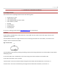
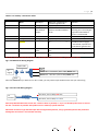
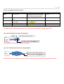
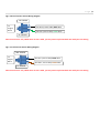
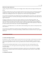
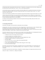
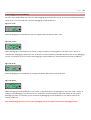
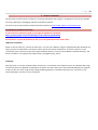
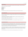
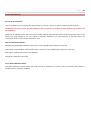
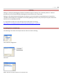
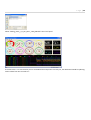
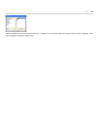
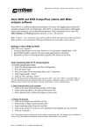
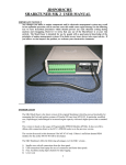
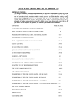
P ag e |1
SLC Pure Plus 2.1 User Manual
Caution !
The Lambda sensor gets very hot, be careful when handling it.
During installation do not insert the Aux 1, Power, and Sensor cables into SLC Pure Plus 2.1, once your wiring is
complete then insert the cables into SLC Pure Plus 2.1. Automotive upholstery is a fantastic static electricity
generator, inserting the cables only after wiring is complete will greatly reduce the chance of damage to the unit by
static electricity.
While the Lambda sensor is in an active exhaust stream, it must be connected and operated with SLC Pure Plus 2.1 at
all times. Carbon from an active exhaust can easily build up on an uncontrolled Lambda sensor and ruin it.
Lambda sensor life when used with leaded fuels is between 100-500 hrs. The higher the metal content the shorter the
life of the Lambda sensor.
Do not install SLC Pure Plus 2.1 in such a manner that the unit is powered before your engine is running. An engine
start can move condensation in your exhaust system to the Lambda sensor, if the sensor is already heated this can
cause thermal shock and cause the ceramic internals inside the sensor to crack and deform.
On some computers the device driver will only be valid for the USB port that was used for initial driver installation.
Plugging SLC Pure Plus 2.1 into a different USB port will prompt your Operating System to ask for a device driver
again, you may install the driver again which will make the current USB port ok for SLC Pure Plus 2.1, it will not
invalidate the driver install for any prior USB ports.
The proper procedure for downloading settings to SLC Pure Plus 2.1 from SLC Config is as follows:
1)
2)
3)
4)
5)
Download setting
Leave SLC Pure Plus 2.1 on for 5 seconds
Turn Power off
Wait 5 seconds
Turn Power On
Failure to follow procedure may result in memory corruption and require a memory reset.
P age |2
1. SLC Pure Plus 2.1 Hardware Installation
1.1 Package Contents
Your SLC Pure Plus 2.1 package should contain the following items
•
•
•
•
•
•
•
•
SLC Pure Plus 2.1 unit
4 Wire Power Cable
6 wire Wideband O2 LSU Sensor Cable
8 wire Auxiliary 1 Cable
O2 Bung
2x fuse holders
2x 250[mA] fuse
2x 5[Amp] fuse
If any item is missing, please contact [email protected] for replacement.
1.2 Fuses
2 Fuse holders, 2x 250ma fuses, and 2x 5A fuses, are provided. You only need 1 fuse of each type, the extra is for
replacement if required.
The fuse holders come with a single continuous wire connecting both ends of the fuse holder, cut the wire at the
midpoint. Do this for both fuse holders.
Fig 1.2.1: Fuse Cut
cut
The fuse holders open easily by twisting and pulling, observe that locking mechanism on the fuse holder is open before
attempting to pull.
In one fuse holder insert a 250mA fuse. The current rating of the fuse is etched on the metallic ends.
In the other fuse holder, insert a 5A fuse.
“System Power” Connects to switched 12[v] through the fuse holder with the 250ma fuse, see section 1.3.
“Heater Power” Connects to switched 12[v] through the fuse holder with the 5A fuse, see section 1.3.
P age |3
1.3 Power, Auxiliary 1, Auxiliary 2, and Sensor
Fig 1.3.1: Power, Aux1, Aux2, and Sensor
Aux 2 Cable
Back of Unit
Aux 1 Con
USB
Power Con
LSU Con
8
7
6
5
6
5
4
4
3
4
3
2
1
3
2
1
2
1
The Power cable has wire colors; Red, Black, Green, and White. The Power cable plugs into the Power connector.
The Auxiliary 1 cable has wire colors; Black, Green, Brown, Red, Orange, Yellow, White, and Blue. The Auxiliary 1 cable
plugs into the Auxiliary 1 connector.
The Auxiliary 2 cable has wire colors; Black, White, Red, Green, and Brown. The Auxiliary 2 cable is soldered directly to
SLC PP2.1, there is no connector.
The Sensor cable has connectors on both ends, one end plugs into LSU Connector on SLC Pure Plus 2.1, the other end
plugs into the Lambda Sensor.
Table 1.3.1: Power Connection Table:
Connector
Pin #
1
Wire Color
Name
Connects to
Note
Red
System Power
Switched 12[v] through 250ma Fuse
Use fuseholder +
250ma Fuse
2
Black
System Ground
3
Blue
LSU Heater Power
If you have a device connected to the
Linear Output, ground this point where the
device is grounded. Otherwise ground to
where ECU is grounded
Switched 12[v] through 5A Fuse
4
Green
LSU Heater Ground
Ground to engine block or chassis
Use fuseholder + 5A
Fuse
P age |4
Table 1.3.2: Auxiliary 1 Connection Table:
Connector Pin #
1
Wire Color
Black
Name
RPM Input
2
3
Green
Brown
Analog Input 2
Simulated
Narrowband
Output
4
5
6
Red
Orange
Yellow
EGT +ve
Analog Input 1
Linear Output
White
Map Sensor
Input
EGT -ve
Connects to
RPM input, tachometer or
low side of ignition coil
0-5[v] output from sensor
Stock ECU if Lambda sensor
replaces stock Narrowband
sensor
14Point7 EGT Probe Red wire
0-5[v] output from sensor
Aftermarket ECU, Datalogger,
etc…
Note
Optional
Optional
Stops Stock ECU from
throwing out a Check Engine
Light when Narrowband
sensor is not detected.
See note under Fig 1.3.3
Optional
Default Output; 0[v] @ 0.68
Lambda Linear to 5[v] @
1.36 Lambda, equivalent to
10-20 AFR for gasoline fuel
Optional
14Point7 MAP Sensor White
wire
8
Blue
14Point7 EGT Probe Blue
See note under Fig 1.3.3
wire
All sensors must be dedicated to SLC PP2.1, you cannot share a sensor between a gauge and SLC PP2.1.
7
Fig 1.3.2: MAP Sensor Wiring Diagram
Nylon Tube
12v
To
Engine
White wire -> SLC PP2.1, Aux 1 cable, White wire
Black wire -> SLC PP2.1, Aux 2 cable, Black wire
Filter
Note: Since there is only 1 Black wire on Aux 2 cable, you may need to split the Black wire with your own wiring.
Fig 1.3.3: EGT Probe Wiring Diagram
To
Exhaust
SLC PP2.1, Aux 1 cable, Red wire
SLC PP2.1, Aux 1 cable, Blue wire
Note: Keep Red and Blue wires on the Aux 1 cable as short as possible, i.e. try to run the EGT probe wires as close to
the Aux 1 connector as possible. EGT probe wires are made of a special material.
EGT Probe must be a k type thermocouple with an ungrounded junction, using a grounded junction EGT probe will
damage SLC Pure Plus 2.1 and void the warranty.
P age |5
Table 1.3.3: Auxiliary 2 Connection Table:
Wire Color
Black
Name
Aux 2 Ground
White
Fluid Temperature Sensor
Input
Air Intake Temperature
sensor input
Fuel Pressure sensor input
Oil Pressure sensor input
Red
Green
Brown
Connects to
Ground for; MAP sensor, Air Intake
Temperature sensor, Oil Pressure
sensor, and Fuel Pressure sensor
14Point7 Fluid Temperature Sensor
Note
Optional
14Point7 Air Intake temperature
sensor Yellow Wire
14Point7 Fuel Pressure sensor
14Point7 Oil Pressure sensor
Optional
Optional
Optional
Optional
All sensors must be dedicated to SLC PP2.1, you cannot share a sensor between a gauge and SLC PP2.1.
Fig 1.3.4: Fluid Temperature Sensor Wiring Diagram
Washer
To
Engine
Block
Nut: turn nut to secure wire
SLC PP2.1, Aux 2 cable, White wire
Note: Copper colored end uses engine block as ground.
Fig 1.3.5: Air Intake Temperature Sensor Wiring Diagram
To
intake
SLC PP2.1, Aux 2 cable, Red Wire
SLC PP2.1, Aux 2 cable, Black Wire
Note: Since there is only 1 Black wire on Aux 2 cable, you may need to split the Black wire with your own wiring.
P age |6
Fig 1.3.6: Fuel Pressure Sensor Wiring Diagram
“M” labelled
To
Engine
Block
SLC PP2.1, Aux 2 cable, Black Wire
SLC PP2.1, Aux 2 cable, Green Wire
“G” labelled
Note: Since there is only 1 Black wire on Aux 2 cable, you may need to split the Black wire with your own wiring.
Fig 1.3.7: Oil Pressure Sensor Wiring Diagram
“WK” labelled
To
Engine
Block
SLC PP2.1, Aux 2 cable, Black Wire
SLC PP2.1, Aux 2 cable, Brown Wire
“G” labelled
Note: Since there is only 1 Black wire on Aux 2 cable, you may need to split the Black wire with your own wiring.
P age |7
1.4 Wideband Sensor Installation
Cars Equipped with Narrowband sensor and stock ECU:
Remove the Narrowband sensor and replace it with the wideband Lambda Sensor. Your ECU will likely show a check
Engine Light if it does not detect the presence of a narrowband signal. Most of the time this can be fixed by routing the
Simulated Narrowband output from SLC Pure Plus 2.1 to the Narrowband signal line to your stock ECU.
If your Narrowband sensor has a heater, in some cases the ECU will also check the heater current, if the Narrowband
sensor’s heater is disconnected the ECU may show a Check Engine Light. This can be fixed by placing a 10W 10ohm
power resistor between the Heater +ve and Heater -ve pins on your Narrowband harness. Alternatively you can leave
just the heater portion of the Narrowband sensor connected to the Narrowband sensor harness and route the
narrowband signal line to SLC Pure Plus 2.1’s Simulated Narrowband Output, make sure the Narrowband signal line is
physically disconnected from the Narrowband sensor.
Alternatively you may keep your Narrowband sensor connected to your ECU and use the “All Others” method.
Cars Equipped Narrowband sensor and aftermarket ECU:
Remove the narrowband sensor from your exhaust and replace it with the wideband Lambda Sensor. Connect the
Linear Output from SLC PP2.1, see Table 1.3.2, to the lambda input of your aftermarket ECU.
All Others:
All others require the welding of the supplied O2 bung to your exhaust system before the catalytic converter. If your car
is turbo charged, weld the bung after the turbo exhaust outlet and before the catalytic converter.
Install the bung such that the sensor is within 90 degrees of vertical, best is within 45 degrees of vertical. This will
reduce the chance of water condensation on the sensor.
Fig 1.4.1: LSU Sensor Angle
<90 Deg
P age |8
Distance from engine exhaust port:
Typically, placing the lambda sensor where your stock oxygen sensor or about 1m from your engine’s exhaust port will
be fine.
Installing the Lambda sensor very close to your engine’s exhaust port may cause the sensor to overheat and expose the
Lambda sensor to high exhaust back pressure. Both will result in erroneous Lambda/AFR readings, overheating the
Lambda sensor will damage the sensor. This is especially true for turbo and super charged applications.
You can monitor the temperature of the Lambda sensor using the Winlog software, see section 6, if you notice that the
Lambda sensor temperature is consistently above 750[C] you should relocate the Lambda sensor farther away from your
engine’s exhaust port.
Installing the Lambda sensor too far from your engine’s exhaust port may cause the following problems; slow
Lambda/AFR response because it takes more time for the exhaust gases to travel a farther distance, if the Lambda
sensor is too close to your exhaust tip this will allow Free Air to mix with your exhaust gases and cause readings to be
overly lean, in some cases SLC Pure Plus 2.1 will not be able to supply enough power to the Lambda sensor’s heater and
the sensor will be too cool this will result in erroneous Lambda/AFR readings.
Furthermore, if the Lambda sensor is in an active exhaust stream while being too cool, carbon can easily build up on the
sensor and ruin it.
You can monitor the Lambda sensor temperature using the Winlog software, see section 6, if you notice that the
Lambda sensor temperature is consistently below 750[C] you should relocate the Lambda sensor closer to your engine’s
exhaust port.
1.5 Grounding Considerations
1.5.1: When Grounding is important
If SLC Pure Plus 2.1 does not need to output an external system via the Linear Output or need to input from an external
system via the analog inputs, then you do not have to worry too much about grounding points, just make sure the
System Ground is grounded near where your ECU is grounded and the LSU Heater Ground is grounded at a different
point.
Interfacing the Simulated Narrowband Output to your ECU technically does require careful grounding, but the
narrowband signal is a very coarse signal, because of that grounding is not generally an issue for the Simulated
Narrowband Output.
Grounding is most critical when interfacing the Linear Output to a device such as an aftermarket ECU or datalogger
because the Linear Output provides very fine representation of AFR/Lambda and this information is usually used to
manage fueling.
1.5.2: Making Good Grounds
P age |9
The System Ground is the ground for the SLC Pure Plus 2.1’s Electronics, this ground carries low current (<100ma) and is
the reference point that SLC Pure Plus 2.1 uses, i.e. this is a very important ground.
The LSU Heater Ground is the ground for the heater inside the Lambda sensor, this ground carries high current (1amp –
3 amp), the LSU Heater Ground is not used as a reference point but only as a path for heater current, i.e. it is not as
important as System Ground.
System Ground should be grounded as close as possible to the ground of the device using the Linear Output. If you have
no device using the Linear Output, then System Ground should be grounded as close as possible to the ground of the
device connected to the Analog inputs for datalogging. If you have no devices connected the Analog Inputs, then System
Ground should be grounded close to your ECU ground.
LSU Heater Ground should be grounded far from where the System Ground is grounded, usually the chassis or the
engine block is a good choice.
1.5.3: Verifying Good Ground
This Section only applies if you have a device connected to the Linear Output.
Good ground is most critical in setups where the Linear Voltage Output is used, SLC Pure Plus 2.1 has a method to verify
the quality of your grounding. By forcing the output to a specific voltage, 2.35[v], and looking at the
AFR/Lambda/voltage read by the device connected to the Linear Output while your engine is under load, you can verify
that the Linear Output is accurate which is indicative that your grounds are good.
If Possible, configure the device connected to the Linear Output with the AFR/Lambda curve “10 AFR @ 0[v] linear to 20
AFR @ 5[v]” or with the Lambda curve “0.68 Lambda @ 0[v] linear to 1.36 Lambda @ 5[v]”.
•
•
•
•
•
•
•
•
•
Install SLC Pure Plus 2.1 according to the prior sections
Install the Lambda sensor according to section 1.4
Connect the Lambda sensor to SLC Pure Plus 2.1 via the supplied sensor cable
Install SLC Config and USB drivers according to Section 4
Start your engine
Connect SLC Pure Plus 2.1 to your Laptop via the supplied USB cable
Run SLC Config according to Section 5
In the “Linear Voltage Output Test” section of SLC Config, click “Force 2.35[v]”
Put normal load on your engine
If the device connected to the Linear Output is configured with the correct AFR/Lambda curve, the AFR read by the
device should always be “14.7”, Lambda should always be “1.00”. Variations of +/- 0.1 AFR or +/- 0.01 Lambda are
acceptable.
If the device connected to the Linear Output is configured to read raw voltages, the voltage read by the device should
always be “2.35[v]”. Variations of +/- 0.08[v] are acceptable.
P a g e | 10
If the AFR/Lambda/Voltage read by the device connected to the Linear Output is consistently above or below
14.7[AFR]/1.00[Lambda]/2.35[v], it is likely the problem is not grounding but with the
configuration/hardware/connection/etc… of the device connected to the Linear Output.
If the AFR/Lambda/Voltage read by the device connected to the Linear Output has large fluctuations around
14.7[AFR]/1.00[Lambda]/2.35[v], the problem is likely due to grounding. I suggest you confirm that the System Ground
connection is clean, well connected, and grounded near where the device connected to the Linear Output is grounded,
move the LSU heater ground to another point farther from the System Ground, and run the test again.
After the Linear Output has been forced to 2.35[v], a subsequent power cycle to SLC Pure Plus 2.1 will restore normal
operation to the Linear Output.
P a g e | 11
2. SLC Pure Plus 2.1 Display and Internal Memory Usage
2.1 Cycling Display Parameters
Fig 2.1.1: SLC PP2.1 faceplate
Quickly pressing the Faceplate Button will cycle the display parameter; AFR, EGT, Boost, Fluid Temperature, Air Intake
Temperature, Fuel Pressue, Oil Pressure, and Datalog Status. You must purchase compatible sensors from 14Point7 and
correctly install the sensors to show corresponding parameters.
All sensors must be dedicated to SLC PP2.1, you cannot share a sensor between a gauge and SLC PP2.1. Only sensors
sold by 14Point7 should be used, using alternate sensors will void your warranty.
Before each parameter is displayed, the name of the parameter will momentarily be shown.
Table 2.1.1: Display Name and Range
Name Shown
Parameter Name
Air to Fuel Ratio
Range of Display
10.26 - 99.99
Exhaust Gas Temperature
0[C] - 1200[C]
Boost
0[PSI] – 43.5 [PSI]
Fluid Temperature
0[C] – 150[C]
Air Intake Temperature
0[C] – 150[C]
Fuel Pressure
0[PSI] – 145[PSI]
Oil Pressure
0[PSI] – 145[PSI]
Datalog Status
0[%] – 100[%]
Note
AFR range depends on the AFR
conversion, for gasoline the range is
10.26 – 99.99
Requires calibration using the SLC
Config software, see section 5.10
Faceplate will only display positive
boost pressure. Real time datalogging
and datalog to Internal Memory will
show Vacuum and Boost
1% = 1.74 minutes
EGT, Boost, Fluid Temperature, Air Intake Temperature, Fuel Pressure, and Oil Pressure parameters are displayed
using a simplified mathematical model. For those metrics there will be a slight difference between the values
displayed on the faceplate and Real Time datalogging/Datalog to Internal Memory.
P a g e | 12
2.2 Datalogging to Internal Memory
SLC PP2.1 has enough memory for 2.9 hours of datalogging @ 25 samples per second. Pressing and holding the faceplate
button for 2 or more seconds will start/stop datalogging to Internal Memory.
Fig 2.2.1: “1 dL”
When datalogging to Internal Memory starts, the display will momentarily show “1 dL”.
Fig 2.2.2: “1xxx”
While datalogging to Internal Memory is active, cycling the display to “Datalog Status” will show “1xxx”, where “1”
indicates that datalogging is active and “xxx” show the % of Internal Memory filled with data from the current datlogging
session. For example, Fig 2.2.2 means that datalogging to Internal Memory is active and that the memory is 88% full.
Fig 2.2.3: “0 dL”
When datalogging to Internal Memory is stopped, the display will momentarily show “0 dL”.
Fig 2.2.4: “0xxx”
While datalogging to Internal Memory is non-active, cycling the display to “Datalog Status” will show “0xxx”, where “0”
indicates that datalogging is non-active and “xxx” show the % of Internal Memory filled with data from the previous
datalogging session. For example, Fig 2.2.4 means that datalogging to Internal Memory is non-active and that the
memory is 88% full.
Each time datalogging is active, the current datalogging session overwrites the previous datalogging session.
P a g e | 13
If SLC PP2.1 is power cycled, SLC PP2.1 will not remember the % of Internal Memory full, however your datalog is
safely stored in flash memory available for download to your PC through the SLC Config software.
When Internal Memory is full, 100%, datalogging to Internal Memory will automatically stop.
P a g e | 14
3. SLC Pure Plus 2.1 First Time Usage
If you have followed instructions up to this point, for a simple setup in which you want to visually display AFR, Boost,
EGT, Fluid Temperature, Air Intake Temperature, Fuel Pressure, Oil Pressure, and/or interface the Linear Output with an
external system such as an ECU or datalogger, you can stop here and enjoy your SLC Pure Plus 2.1 unit as is. Your SLC
Pure Plus 2.1 will be able to achieve 0.01 Lambda accuracy without any additional steps.
Continue on reading if you desire additional features such as Datalogging and Free Air Calibration.
P a g e | 15
4. Software Installation
You will need to install 2 pieces of software; SLC Config and Winlog. SLC Config is a configuration utility for SLC lambda
controllers, Winlog is a datalogging and data visualization software.
For the most up to date software and documentation please visit http://www.14point7.com/Support.php
4.1 USB Driver Installation and Usage
A video tutorial is available to guide you through the USB Driver Installation,
https://groups.google.com/forum/#!category-topic/14point7/jTP201oClA4
SLC Pure Plus 2.1 cannot be powered by USB, it must be powered from the Power cable.
USB Driver Installation:
Power on SLC Pure Plus 2.1, connect SLC Pure Plus 2.1 to your PC’s USB port using the supplied USB cable. Windows will
notify you that it has detected a new device and ask you for the location of the driver. The driver location is in the
“\Driver\SLC_PP2.1” directory of the SLC Config installation directory. If you used the default installation directory, the
driver is located in “C:\Program Files\14Point7\SLC_Config\Driver\SLC_PP2.1”.
ComPort#:
Once the driver is correctly installed and SLC Pure Plus 2.1 is connected to the USB port of your PC, Windows will assign
a Communications Port Number (ComPort#) to the device. You will need to know the ComPort# Windows has assigned
to SLC Pure Plus 2.1 when using the SLC Config and Winlog software. In Windows XP/Vista/7 you can check in your
“Device Manager” to find the correct ComPort#.
P a g e | 16
Fig 4.1.1: Device Manager, ComPort#
In the above example, the correct ComPort# is “COM3”.
On some computers the device driver will only be valid for the USB port that was used for initial driver installation.
Plugging SLC Pure Plus 2.1 into a different USB port will prompt your Operating System to ask for a device driver
again, you may install the driver again which will make the current USB port valid for SLC Pure Plus 2.1, it will not
invalidate the driver install for any prior USB ports.
P a g e | 17
5. SLC Config
5.1 Reset SLC Memory
The proper procedure for downloading settings to SLC Pure Plus 2.1 from SLC Config is as follows:
1)
2)
3)
4)
5)
Download setting
Leave SLC Pure Plus 2.1 on for 5 seconds
Turn Power off to SLC Pure Plus 2.1
Wait 5 seconds
Turn Power On to SLC Pure Plus 2.1
Failure to follow procedure may result in memory corruption and require a memory reset.
Symptoms of memory corruption:
•
•
•
•
Linear Voltage Output is static regardless of exhaust Lambda
Simulated Narrowband output is static regardless of exhaust Lambda
Numeric Display on SLC Pure Plus 2.1 is static regardless of exhaust Lambda
Numeric Display on SLC Pure Plus 2.1 is blank or the refresh rate is too high or too low
Memory corruption can be fixed by hitting the “Reset SLC Memory” button in the SLC Config software, this will reset the
memory onboard SLC Pure Plus 2.1 with safe default values. After a memory reset, all previous stored settings will be
lost.
5.2 Query Device
Specify the correct ComPort# and hit the “Query Device” Button, SLC Config will interrogate the connected USB device
at the selected ComPort#, see section 4.1, and automatically unlock functionality specific to your SLC Pure Plus 2.1
model.
You must perform a “Query Device” before being able to change and adjust SLC Pure Plus 2.1 settings.
P a g e | 18
5.3 AFR Conversion
Lambda is converted to Air-to-Fuel Ratio (AFR) by a multiplication factor; AFR=Lambda * AFR Conversion. Below is a
table of Conversion Factors for various fuels
Gasoline 14.7
LPG (Propane) 15.5
Methanol 6.4
Ethanol 9.0
CNG 17.2
Diesel 14.6
Hit the “Write AFR Conv Settings” button to download a new AFR Conversion setting to SLC Pure Plus 2.1.
5.4 Linear Voltage Output
This section allows you to adjust the 0-5[v] linear representation of AFR/Lambda. The linear voltage output from SLC
Pure Plus 2.1 is typically connected to your datalogger or aftermarket ECU to convey the measured AFR/Lambda of your
exhaust gas to that device.
The default Voltage vs Lambda output is; 0[v] @ 0.68 Lambda linear to 5[v] @ 1.36 Lambda, for gasoline this is
equivalent to 0[v] @ 10 AFR linear to 5[v] @ 20 AFR.
To change the Voltage vs Lambda output, you must specify the Lambda @ 0v and the Lambda @ 5v, all points in
between will be automatically linearly interpolated.
Hit the “Write Vout Settings” button to download new Linear Voltage Output settings to SLC Pure Plus 2.1.
5.5 Narrowband Switch Point
This section allows you to adjust the Simulated Narrowband output. In some SLC Pure Plus 2.1 installations, the Lambda
sensor will physically replace the stock narrowband sensor and the Simulated Narrowband output from SLC Pure Plus
2.1 is connected to the Narrowband Signal wire feeding your ECU. Your ECU controls fuel enrichment of your engine at
light engine loads based on the output of the Simulated Narrowband signal, the ECU’s goal is to maintain the engine at
stoich to maximize efficiency and minimize pollution at light engine loads.
The default Lambda Switch Point is “1 Lambda”, at Lambda =1 the Simulated Narrowband Voltage is 0.45[v]. When your
ECU sees 0.45[v] it will believe that the engine is running stoich. By shifting the switch point to below 1 Lambda, your
engine will run richer at light engine loads. By shifting the switch point above 1 lambda, your engine will run leaner at
light engine loads.
Hit the “Write NB Switch Point” button to download a new Narrowband Switch Point to SLC Pure Plus 2.1.
P a g e | 19
5.6 RPM Configuration
This section allows you to adjust the RPM Pickup settings to match your engine’s ignition configuration.
Table 5.6.1: RPM Multiplier
Ignition Type
Coil on Plug
Wasted Spark
Distributor
Distributor
Distributor
Distributor
Distributor
Distributor
Distributor
Distributor
Distributor
Distributor
Distributor
Distributor
Distributor
Distributor
Distributor
# of Cylinders
Does not matter
Does not matter
2
3
4
5
6
7
8
9
10
11
12
13
14
15
16
SLC Config RPM Multiplier
0.5
1
1
0.667
0.5
0.4
0.334
0.286
0.25
0.222
0.2
0.182
0.167
0.154
0.143
0.133
0.125
5.7 Linear Voltage Output Test
This section allows you to force the Linear Output to a static 2.35[v] for the purpose of testing the quality of your ground
wiring. Refer to section 1.5 for more information.
P a g e | 20
5.8 Free Air Calibration
5.8.1: Free Air Calibration
Free Air Calibration uses the known O2 concentration of “Free Air”, 20.9%, as a gas to calibrate a Lambda sensor.
SLC Pure Plus 2.1 with a sensor in good condition is able to achieve 0.01 Lambda accuracy without the need for Free
Air Calibration.
A bad Free Air Calibration will cause inaccurate Lambda readings, often the error will be small enough such that it is not
obvious yet large enough to put your engine in jeopardy. Therefore, it is very important to correctly follow the
instructions shown in the “Free Air Calibration” form.
Free Air Calibration Schedule:
Normally Aspirated Engine: Calibrate once a year or every 40,000 miles, whichever comes first.
Turbo/Super Charged Engine: Calibrate once every 6 months or every 20,000 miles, whichever comes first.
Race Engine: Calibrate every other race weekend.
Dynometer: Calibrate once a week.
5.8.2: “Reset Calibration Value”
The “Reset Calibration Value” button will reset the free Air calibration to a factory value, the factory value reflects a
Lambda sensor in “perfect” condition.
P a g e | 21
5.9: EGT Calibration
EGT Calibration calibrates the attached Exhaust Gas Temperature Probe for increased accuracy. It is important to
correctly follow the instructions in the “EGT Calibration” form.
Once EGT calibration is complete, the software will show the “EGT Calibration Value”, you enter this value into the
Winlog application in the “Winlog Config” form, see section 6.1.
5.10: Internal Memory->Download Datalog From Internal Memory
Clicking “Download Datalog From Internal Memory” from the “Internal Memory” menu item, will download the datalog
session saved on Internal Memory onboard SLC Pure Plus 2.1 to your PC’s hard disk. The data is saved in “CSV” format
with a comma separating each data field. The data is easily readable by a spreadsheet program such as Microsoft Excel
and a data visualizer such as WinlogView. When using WinlogView to view datalogs downloaded from Internal
Memory, make sure you set the file filter to “CSV Log Files {*.csv}” to be able to see “CSV” files.
P a g e | 22
6. Winlog
Winlog is a third party Datalogging and Data Visualization program. Winlog is not created by 14Point7. 14Point7
provides a full and unrestricted copy of Winlog with every SLC Pure Plus 2.1 purchase.
Winlog is a fully featured and powerful piece of software, you should read the installed Winlog user manual for a
complete understanding of its capabilities. The following Winlog instructions only touch upon very basic features to
allow the user to quickly get started.
It is a good idea to watch this short Winlog tutorial video before continuing,
www.14Point7.com/Support/Software_Documentation/Winlog_SLC_Tut1.wmv
6.1: Winlog Driver and Dash Setup
The following instructions will setup the SLC Pure Plus 2.1 Driver in Winlog.
View->Device Configuration
Click Add
Click Add
Select “SLC PP2.1, Driver Version x.xx” then click “ok”
P a g e | 23
Select the correct serial port, see section 4.1
Input the correct RPM Multiplier for your engine, see section 5.6
Input the desired AFR Conversion, see section 5.3
Input the EGT Calibration Value, see section 5.10
Input the 4 Accelerometer Calibration Values, see section 5.8
Click “OK”
Click “OK”
File->Open Dashboard
P a g e | 24
Select “Winlog_Dash_x_xx_SLC_PP2.1_1024_600.dsh” then click “Open”
If SLC Pure Plus 2.1 is connected to your PC via USB and the Comport# is correctly set, the dashboard should be updating
with live data from SLC Pure Plus 2.1.
P a g e | 25
6.2: Winlog, Saving Datalog to Disk
File->New Datalog
Winlog by default will automatically generate a filename based on time and date and save the datalog file to the Winlog
installation directory, you can change this in View->Dash Configuration.
File->Stop Logging, will stop datalogging to Hard Disk.
P a g e | 26
7. WinlogView
WinlogView is a program to view datalogs saved from Winlog and datalogs downloaded from SLC Pure Plus 2 Internal
Memory via SLC Config, see section 5.11.
WinlogView is a fully featured and powerful piece of software, you should read the installed WinlogView user manual
for a complete understanding of its capabilities. The following WinlogView instructions only touch upon very basic
features to allow the user to quickly get started.
File->Open Log
Browse to where the saved datalog is located and click “Open”
View->Fields
P a g e | 27
Select the fields you want to display with the “->” button. In the “X Axis Field” you usually want to select “Logtime”. Click
“Ok” to display the data in graph form.
P a g e | 28
8. Warranty
14Point7 warrants this product to be free from defects for 2 years. Sensors if purchased from 14Point7 carry no
warranty whatsoever. Warranty does not cover user error and abuse. Warranty period is based on date of purchase, if
no proof of purchase date is provided; warranty will be based on the Program Date label on the underside of the PCB. In
the event that neither proof of purchase date can be provided and the Program Date label is illegible or removed; no
warranty will be provided. Warranty is transferrable so long as proof of original purchase date can be provided or
Program Date label is legible.
9. Disclaimer
14Point7 is liable for damages only up to the purchase price of its products. 14Point7 products should not be used on
public roads.