1
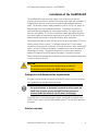
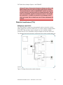
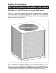
SKF Online Motor Analysis System NetEP/iNetEP Installation Guide Part No. 71-051-Vb EN SKF Online Motor Analysis System PUB CM/I1 71-051 EN NetEP/iNetEP Installation Guide V-b SKF Online Motor Analysis System NetEP/iNetEP Installation Guide Part number: 71-051-V2-EN Copyright 2013, SKF USA All rights reserved. SKF USA – Condition Monitoring 4812 McMurry Ave. Suite 100 Fort Collins, CO 80525 (970) 282-1200 (970) 282-1010 (FAX) 800-752-8272 (USA Only) Information furnished in this manual by SKF USA – Condition Monitoring, is believed to be accurate and reliable. However, SKF assumes no responsibility for the use of such information or for any infringements of patents or other rights of third parties that may result from its use. No license is granted by implication or otherwise under any patent rights of SKF. No part of this document may be reproduced in part or in full by any means, such as photocopying, photographs, electronic recording, videotaping, facsimile, etc., without written permission from SKF USA, Fort Collins, Colorado. NOTICE SKF assumes no liability for damages consequent to the use of this product. CAUTION Please read and thoroughly understand the contents of this entire guide before performing any installation of this product. Failure to follow the instructions and safety precautions in this manual can result in serious injury, damage to the product, damage to other equipment, or a malfunctioning system. Keep this guide in a safe and ready location for future reference. NetEP/iNetEP Installation Guide—71-051-V2-EN i License agreement, warranties Declaration of conformity Manufacturer’s Name and Address: SKF USA Condition Monitoring 4812 McMurry Ave. Fort Collins, CO. 80525 USA Equipment Description: Electric Motor Monitoring System Equipment Model Designations: NetEP Application by Council Directive 72/23/EC on the harmonization of the laws related to Member States relating to electrical equipment designed for use with certain voltage limits, as amended by: Council Directive 93/68/EC and Council Directive 2004/108/EC on the approximation of the laws related to Member States relating to the electromagnetic compatibility, as amended by: Council Directive 93/68/EC. Note: due to the phenomena being served and the material properties being measured, this equipment does radiate radiofrequency energy while in the active test mode. Referenced Safety Standards: EN 61010-1, CAN/CSA-C22.2 61010-1 Referenced EMC Standards: 61326:2001 55011 Class A EN 61000-3-2 EN 61000-3-3 EN 61000-4-2 EN 61000-4-3 EN 61000-4-4 EN 61000-4-5 EN 61000-4-6 EN 61000-4-8 EN 61000-4-11 I., the undersigned, hereby declare that the equipment standard above conforms to the above directives and standards. Signature: Printed Name: Mike Teska Title: Engineering Manager Limited Warranties; Disclaimer NetEP/iNetEP Installation Guide – PUB CM/I1 71-051-V2-EN ii License agreement, warranties (a) SKF’s sole and exclusive warranties with respect to the related Instruments and Software are set forth in this User’s Manual. (b) EXCEPT AS SET FORTH IN THIS USER’S MANUAL AND TO THE EXTENT PERMITTED BY APPLICABLE LAW, ALL EXPRESS AND/OR IMPLIED WARRANTIES OR CONDITIONS, INCLUDING, BUT NOT LIMITED TO, IMPLIED WARRANTIES OR CONDITIONS OF MERCHANTABILITY, MERCHANTABILITY OF A COMPUTER PROGRAM, INFORMATIONAL CONTENT, SYSTEM INTEGRATION, FITNESS FOR A PARTICULAR PURPOSE, AND NON-INFRINGEMENT, ARE HEREBY DISCLAIMED AND EXCLUDED BY SKF. Limitations on Liability (a) Limitations and Exclusions. IN NO EVENT WILL SKF BE LIABLE TO LICENSEE FOR ANY DIRECT, INDIRECT, INCIDENTAL, CONSEQUENTIAL, PUNITIVE OR OTHER SPECIAL DAMAGES, LOST PROFITS, OR LOSS OF INFORMATION SUFFERED BY LICENSEE ARISING OUT OF OR RELATED TO THE SOFTWARE OR RELATED INSTRUMENTS OR THE USE OF THE SOFTWARE OR RELATED INSTRUMENTS, FOR ALL CAUSES OF ACTION OF ANY KIND (INCLUDING TORT, CONTRACT, NEGLIGENCE, STRICT LIABILITY, BREACH OF WARRANTY OR CONDITION, AND STATUTORY) EVEN IF SKF HAS BEEN ADVISED OF THE POSSIBILITY OF SUCH DAMAGES. THE PRECEDING EXCLUSION AND DISCLAIMER OF DAMAGES SHALL APPLY TO ALL CLAIMS MADE BY LICENSEE RELATED TO OR ARISING OUT OF LICENSEE’S USE OF THE SOFTWARE, INCLUDING, BUT NOT LIMITED TO, CLAIMS ALLEGING THAT THE SOFTWARE, OR ANY COMPONENT THEREOF, FAILED OF ITS ESSENTIAL PURPOSE OR FAILED IN SOME OTHER RESPECT. (b) Acknowledgment. You agree that the limitations of liability and disclaimers of warranty set forth in this Software License will apply regardless of whether SKF has tendered delivery of the Software or you have accepted the Software. You acknowledges that SKF has set its prices and granted the licenses contemplated herein in reliance on the disclaimers of warranty and the limitations and exclusions of liability set forth in this Software License, and that the same form an essential basis of the bargain between the Parties. NetEP/iNetEP Installation Guide – PUB CM/I1 71-051-V2-EN iii License agreement, warranties Term and Termination (a) Term. The licenses granted herein shall commence on your acceptance of the terms of this Software License, and shall continue in existence until it is terminated in accordance with Section 3(b) below. (b) Termination. SKF may terminate this Software License and the license conveyed hereunder in the event that you breaches any provision, term, condition, or limitation set forth in this Software License, including but not limited to the license restrictions set forth in Section 2(b) of this Software License. (c) Effect of Termination. Within ten (10) days after termination of this Software License and the licenses granted hereunder, you shall return to SKF, at your expense, the Computer Software and all copies thereof, and deliver to SKF a certification, in a writing signed by an officer of you, that all copies of the Computer Software have been returned to SKF and that you has complied with the requirements of this Section 3(c). Assignment You may assign this Software License in connection with the sale or other transfer of the Instrument, provided, that the transferee agrees in writing to be bound by the terms of this Software License. Except as authorized by the preceding sentence, you shall not assign or otherwise transfer the Software or this Software License to anyone, including any parent, subsidiaries, affiliated entities, or third Parties, or as part of the sale of any portion of its business, or pursuant to any merger, consolidation, or reorganization, without SKF's prior written consent. Any assignment or transfer effected in violation of this Section 4 shall be void ab initio and of no force or effect. General The validity and interpretation of this Software License shall be governed by Colorado Law except as to copyright and other proprietary matters, which may be preempted by United States laws and international treaties. In the event of any violation of this Software License, SKF reserves the right to pursue any state law remedies (including contractual remedies) or remedies under federal laws or both. You consents to exclusive jurisdiction in either state or federal courts in Colorado or both as appropriate and agrees that the prevailing party shall be entitled to its attorney fees and costs. No decision, act or inaction of SKF, shall be construed to be a waiver of any right or remedy, and pursuit of any state or federal causes shall not be deemed an election or remedies. In the event of any provision of this Software License shall be deemed unenforceable, or void, or invalid, such provision shall be modified so as to make it valid and enforceable and as so modified the entire agreement shall remain in full force and effect. NetEP/iNetEP Installation Guide – PUB CM/I1 71-051-V2-EN iv License agreement, warranties This Software License sets forth the entire understanding and agreement between the parties and no written or oral representative of any kind whatsoever shall in any way modify or expand the terms of this User’s Manual. In the event of any conflict or inconsistency between the terms of this Software License and any Documentation, this agreement shall preempt such documentation to the extent inconsistent. NOTICE All material associated with this Software License is copyrighted material. Federal law provides severe civil and criminal penalties for the unauthorized reproduction, distribution, or use of copyrighted materials (Title 17, United States Code). The Federal Bureau of Investigation investigates allegation of criminal infringement for enforcement. Technical assistance/authorized service centers Visit www.skf.com under the condition monitoring/electric motor test and monitoring pages, or www.bakerinst.com for technical assistance / authorized service center information. This information will be marked with an asterisk. Service department phone number: (970) 282-1200 or toll free at (800) 7528272. Trademarks Microsoft, Windows, Internet Explorer, and Windows 7 are either registered trademarks or trademarks of Microsoft Corporation in the United States and/or other countries. All other trademarks, service marks, or registered trademarks appearing in this manual are the trademarks, service marks, or registered trademarks of their respective owners. NetEP/iNetEP Installation Guide – PUB CM/I1 71-051-V2-EN v Table of Contents About this guide .......................................................................................... 1 Formatting...................................................................................................................... 1 Information devices ....................................................................................................... 1 Symbols on equipment ................................................................................................. 2 Additional safety alerts .................................................................................................. 2 Operational safety warnings .........................................................................................3 Environmental conditions ............................................................................................. 3 Pollution degree II.......................................................................................................... 4 Positioning equipment .................................................................................................. 4 Cleaning and decontamination .....................................................................................4 Unpacking the unit......................................................................................................... 4 Installation of the NetEP/iNetEP ................................................................. 6 Voltage bus and disconnection requirements .............................................................6 Interior overview ............................................................................................................ 6 Potential transformers (PTs) ........................................................................................8 Physical connections to the NetEP voltage inputs................................................... 10 Current Transformers and their connection ............................................. 12 Installation of Current Transformers on motor leads ............................................. 12 NetEP/iNetEP setup .................................................................................. 19 Appendix 1—Calibration Settings dialog box ............................................ 43 Appendix 2—NetEP configuration ............................................................. 45 Scope ........................................................................................................................... 46 View Connections........................................................................................................ 47 Index ............................................................................................. 49 NetEP/iNetEP Setup Guide – 71-051-V2-EN vii Table of contents NetEP/iNetEP Installation Guide – PUB CM/I1 71-051-V2-EN viii About this guide This guide uses the following conventions in formatting, and informational devices to help you more clearly identify specific elements and information. Formatting Interface items are set in bold. Page or window names are set in italics. File names are set in courier font. Information devices Information requiring special attention is set in the following format and structure: NOTE Indicates additional information about the related topic that deserves closer attention or provides a tip for using the product. NOTICE Indicates information about product usage that can result in difficulty using product if not heeded. CAUTION Indicates a hazardous situation with potential for minor to moderate injury, or property damage. WARNING Indicates a hazardous situation with risk of death or serious bodily injury. NetEP/iNetEP Setup Guide – 71-051-V2-EN 1 SKF Online Motor Analysis System – Net EP/iNetEP Symbols on equipment Symbol/Label Description Protective conductor terminal. Located beside black ground test lead on front panel of instrument. Earth (ground) terminal. Frame or chassis terminal. Located on rear panel of instrument by ground terminal. Warning about hazardous voltage and risk of severe electrical shock or death. Located beside each red test lead on front panel of instrument. Danger notice label warning about … Additional safety alerts WARNING The NetEP/iNetEP must not be exposed to water or moisture, even with the cabinet securely closed. This instrument is not water resistant with its door either open or closed. Do not allow the instrument to be exposed to water, especially if the cabinet is open. Any water that comes in contact with electronics inside the instrument can harm or destroy the device, and can also result in serious injury and/or death to people working in or around the instrument. CAUTION The maximum rating of the NetEP/iNetEP is 1,000 V AC; 1,000 V AC operation is the maximum allowable voltage between any two of the four voltages and the ground clip. Under no circumstances should NetEP/iNetEP Installation Guide – PUB CM/I1 71-051-V2-EN 2 SKF Online Motor Analysis System – Net EP/iNetEP the voltage sensing circuit be connected to higher voltage levels. This will cause severe damage to the instrument. Operational safety warnings Any installer or operator of this equipment must adhere to the following safety precautions: Comply with all of your organization’s mandated safety practices at all times. Ensure that the installation location of the NetEP unit does not interfere with site (or facility) power current or adversely impact any site operations. To avert or avoid dangerous shock hazards: 1. Use all mandated safety equipment required of your organization for performing installations of electrical equipment, including eye protection, high voltage gloves, arc-flash rated masks, hoods and any required PPC (personal protective clothing). 2. Ensure that the site organization’s appropriate lockout /tag-out procedures are properly understood and implemented by all personnel involved in this installation. 3. Ensure each rotating system to be monitored IS POWERED DOWN (OFF) and inoperable before installation of this instrument begins. Each and every connection at the motor control center (MCC) must be connected ONLY when the rotating system is powered down/off and inoperable. 4. Do not position motor phase connections near any ground, or near one another. 5. Do not use or install this instrument in explosive environments. This instrument is NOT approved for use in any flammable or hazardous environments. 6. Install an external disconnect switch for AC power to the NetEP (this is required). This disconnect switch should be within three feet of the NetEP’s permanent mounting position. This is necessary because there is no internal fusing or disconnect for AC power with the NetEP. Environmental conditions 1. The NetEP is designed strictly for indoor use. Testing of this unit has been completed for use up to 2000 meters of altitude. 2. This monitoring device operates in temperatures ranging from 32 to 120 degrees Fahrenheit (5° C to 50° C). NetEP/iNetEP Installation Guide – PUB CM/I1 71-051-V2-EN 3 SKF Online Motor Analysis System – Net EP/iNetEP 3. Installation for this instrument is an IEC Category III in a Pollution Degree II environment (refer to IEC 61010-1 3.6.6.2). 4. This instrument is NOT waterproof or sealed against water entry with the cabinet door open OR closed. 5. This system NOT approved for use in explosive environments. Pollution degree II This device adheres to Pollution Degree II specifications sourced from IEC 610101 3.6.6.2. Only non-conductive pollution occurs with this instrument. However, temporary conductivity caused by condensation can be expected. Positioning equipment Do not position equipment in such a way that it is difficult to operate the power disconnection device(s). Maintain a clearance of 36 inches in front of the NetEP/iNetEP to allow for opening the door for installation/removal of internal components, and for maintenance and connections. All connections to the NetEP/iNetEP are through the bottom of the cabinet, so it must be mounted with at least 36 inches of vertical free/clear space below the unit. The NetEP/iNetEP does not require any additional air to keep the unit cool, so airflow at the mounting location is not of concern. Cleaning and decontamination Keep the NetEP or iNetEP clean and in a dry environment. To clean the unit, power it down (off) and de-energize all voltage bus connections, including the AC power to the unit. Wipe with a clean, water-dampened cloth. Do not submerge in water or other cleaners or solvents. Use a soft cotton cloth dampened with water to clean the computer screen (iNetEP only) and gently wipe the surface. Products designed specifically to clean LCD television windows or monitors may be used as well. Unpacking the unit Carefully remove the following items from the shipping boxes: The NetEP or iNetEP CTs Installation Guide User Manual Software CD Termination operating tool NetEP/iNetEP Installation Guide – PUB CM/I1 71-051-V2-EN 4 SKF Online Motor Analysis System – Net EP/iNetEP NetEP/iNetEP Installation Guide – PUB CM/I1 71-051-V2-EN 5 SKF Online Motor Analysis System – Net EP/iNetEP Installation of the NetEP/iNetEP The NetEP/iNetEP requires certain aspects to its location for permanent mounting of the instrument’s cabinet. The location must allow safe installation of voltage and current lines to the unit in accordance with applicable electrical codes. The location must be readily accessible to 120 V or 240 V AC power, an Ethernet LAN (Local Area Network) connection. It should be mounted on a vertical surface approximately 36 inches above the floor (36 inches from the bottom of the cabinet). The surface to which the cabinet gets affixed should be more than capable of permanently supporting a 40 pound, 20-inch by 30-inch cabinet without obstructing or being obstructed by other equipment. The location must also be within 150 feet of the current transformers (CTs) to be used to monitor motor currents. To facilitate wiring of the CTs and voltage connections, there must be a minimum of 36 inch clearance in front of the NetEP cabinet. A foot (12 inches) of clearance is needed on each side of the cabinet to adequately rout cables. The ambient temperature of the location should be between 32 degrees F and 120 degrees Fahrenheit. Vibration is minimal. There should also be enough space available to mount the voltage bus disconnect in close proximity to the unit. CAUTION All voltage busses must be de-energized using an external disconnection switch before the NetEP cabinet is opened. Voltage bus and disconnection requirements AC power is wired through the bottom of the NetEP cabinet, and must be wired using established or mandated electrical codes. NOTICE An external breaker or disconnect is required to safely remove the NetEP from its power source; the NetEP itself has no fuses or breakers inside the cabinet for the AC power circuit/supply. The NetEP has a universal input power system, and should be supplied with a 110 V to 240 V source, and at 50/60 Hz with ground. The unit draws less than two amps. Interior overview NetEP/iNetEP Installation Guide – PUB CM/I1 71-051-V2-EN 6 SKF Online Motor Analysis System – Net EP/iNetEP Figure 1 shows the interior of the NetEP. Note the cable routing channel for the current transformer (CT) cables along the right hand side of the unit. Voltages are routed along the left side. It is important to route the voltage bus cables along the side of the unit as far as possible from the circuit boards, as shown in the figure. Voltage inputs can enter the unit from the bottom of the unit or through the conduit knockouts on the left side of the unit. Figure 1: iNetEP cabinet interior. NOTICE There are no user-serviceable parts inside the unit. WARNING AC power and the measurement voltage busses to the NetEP should always be disconnected before the cabinet door is opened. Even NetEP/iNetEP Installation Guide – PUB CM/I1 71-051-V2-EN 7 SKF Online Motor Analysis System – Net EP/iNetEP with the AC power disconnected, dangerous voltage may exist on the NetEP voltage input cards that can cause serious injury or death. The electronic boards inside the NetEP/iNetEP cabinet are sensitive to static electricity, and may contain live voltage heat sinks. Do not touch any component except the connectors for the CT and voltage bus connections. In addition to potential circuit damage, electric shock and severe injury or death may occur if these components are touched. Potential transformers (PTs) Voltage bus connections Each NetEP/iNetEP voltage bus to be monitored requires connection to threephase voltage (not in excess of 1000 V AC). For motors rated at voltages greater than 1000 V AC, secondary output voltages from user-installed potential transformers (PTs) are acceptable as long as voltages are less than 1000 V AC. The following schematic illustrates a voltage disconnect switch installed within the system. Figure 2: Voltage disconnection switch schematic. NetEP/iNetEP Installation Guide – PUB CM/I1 71-051-V2-EN 8 SKF Online Motor Analysis System – Net EP/iNetEP CAUTION As noted above, a voltage disconnection switch must be installed within the prescribed industry standard distance of the NetEP/iNetEP; in-line between the unit and the voltage source. Make sure the Phase A – Phase B – Phase C progression is correct and maintained between the voltage lines (if line connected) and the 1000 V input boards in the unit. If connected directly to a three-phase bus, make the following connections: The NetEP input board phase A to voltage bus phase A The NetEP input board phase B to voltage bus phase B The NetEP input board phase C to voltage bus phase C The NetEP input board N = no connection If connected via a potential transformer (PT), confirm that the PT connection is proper and the PT output connection is properly connected to the 1000 V input board. Figure 3: A typical potential transformer (PT). Primary connections Voltage bus phase A to 1H1 Voltage bus phase B to 2H1 Voltage bus phase C to 3H1 Secondary connections The NetEP/iNetEP input board phase A to 1X1 The NetEP/iNetEP input board phase B to 2X1 The NetEP/iNetEP input board phase C to 3X1 The NetEP/iNetEP input board N = no connection NetEP/iNetEP Installation Guide – PUB CM/I1 71-051-V2-EN 9 SKF Online Motor Analysis System – Net EP/iNetEP The secondary ground (2X1) requires an appropriate station ground somewhere near the PT itself. Do not tie the 2X1 to the NetEP/iNetEP ground. This ground will not be the same potential as station ground. If a ground connection is made, a ground loop will be formed and possibly a very high current will flow in the ground conductor. Physical connections to NetEP voltage inputs 1. De-energize the voltage inputs at disconnect. 2. Completely turn off the NetEP/iNetEP by shutting down the computer and disconnecting AC from the unit. 3. Run the voltage conductors, appropriately rated, through the bottom of the unit or to the left side of the unit where knockouts are provided. The knockouts provided are 7/8 (.875) inch diameter and are sized for a 1/2 (.5) inch trade size conduit fitting. 4. Run the voltage conductors along the left wall of the box. 5. Select a voltage channel for the bus and connect the conductors to the terminal blocks on the voltage input cards using the provided operating tool. Make sure all strands are captured inside the terminal block. CAUTION Confirm the voltage input wiring for each phase is completely captured by its corresponding phase in the unit voltage connector; that is, no frayed wire strands poke out. The backplane board has printed channel numbers that identify the NetEP voltage bus connections as shown below. Figure 4: Backplane board. NetEP/iNetEP Installation Guide – PUB CM/I1 71-051-V2-EN 10 SKF Online Motor Analysis System – Net EP/iNetEP If necessary, the voltage input card may be removed to make connections. Use a long flat blade screwdriver to unscrew the voltage input board from the backplane board. Gently remove the board from the multi row connector. Figure 5: Properly installed voltage inputs. To replace the board, align and firmly press the connectors together, then tighten the screws on the brackets. Figure 6: Improperly installed voltage input conductors—note the frayed strands. NetEP/iNetEP Installation Guide – PUB CM/I1 71-051-V2-EN 11 SKF Online Motor Analysis System – Net EP/iNetEP Current Transformers and Connections Using the correct current transformer (CT) for each motor is important for acquisition of precise data. The normal operating current of the motor should fall between 10 and 90 percent of the CT’s current rating. For example, SKF 200 A CTs should be used for motors with a normal operating current (per phase) of 20 A to 180 A. SKF CTs have been chosen for their consistency of performance, safety, stability of calibration and transient responsiveness, and should be used with this system. After installation of the voltage bus above, install each supplied set of three CTs for each motor being monitored. Be sure the appropriate CT rating is used for each motor connector. Install the supplied CTs either directly on the motor leads themselves or on the secondary circuit of a user-installed meter/relay CT. Installation of Current Transformers on motor leads WARNING Make sure all equipment and voltage disconnects are in the off position prior to proceeding with this operation; dangerous voltages may be present and pose a hazard than can cause serious injury or death. If the supplied CTs are installed directly on the motor feeder cables, follow these instructions: 1. Place the CTs on the load-side of any line protection devices (circuit breakers). Confirm that the CTs all face the same way, preferably towards the motor as indicated by the dot or arrow on the CT. The photo below shows CTs attached on the load side of a disconnect switch (CTs are circled in red). Wires from each CT run to a (user-provided) black connection box at the bottom (circled in orange). The wiring from the CT connection box is connected to the NetEP using a CAT V cable. NetEP/iNetEP Installation Guide – PUB CM/I1 71-051-V2-EN 12 SKF Online Motor Analysis System – Net EP/iNetEP Figure 7: Motor lead cabinet. 2. Confirm that the cable is long enough to connect to the NetEP/iNetEP unit. 3. When using a CAT V cable, use the blue pairs for phase A, the green pairs for phase B and the orange pairs for phase C. 4. Route the (CAT V) cables in a tray or conduit to the NetEP/iNetEP unit. 5. Using the supplied cable strain reliefs, route the CT cable through the bottom panel of the NetEP and along the right hand side of the box inside the cable routing channel. Be sure to leave enough length on the CT cable to make connections to the terminal blocks. NetEP/iNetEP Installation Guide – PUB CM/I1 71-051-V2-EN 13 SKF Online Motor Analysis System – Net EP/iNetEP Figure 8: Terminal block. 6. Cut to length, and connect each phase from each motor to each respective phase and motor connection location. Do so by carefully opening the connector contact with the tool provided, and inserting the wire. Each connector has the motor number printed on the board next to the connector. NetEP/iNetEP Installation Guide – PUB CM/I1 71-051-V2-EN 14 SKF Online Motor Analysis System – Net EP/iNetEP Installation of CTs on an existing secondary 1. Pull a CAT V cable or other twisted pair instrumentation cable from the NetEP/iNetEP box to the interior of the motor cabinet. NOTE If monitoring several motors, it may prove useful to pull several cables at the same time, preferably in different colors). 2. Route the CT cable inside the cabinet with requisite adherence to appropriate or mandated industrial codes and industry practices. 3. Strip the outer jacket of the cable back 6–12 inches and insert the twisted pairs into the ends of the CT wiring as in the photo below. Use the blue pair for phase A, green pair for phase B, and the orange pair for phase C. Regarding the brown pair, do not cut if off, but wrap it around the body of the cable in case it is needed to replace a damaged blue/green/orange twisted pair. Figure 9: CT installation. 4. Install the CT around the secondary of the user-installed relay/meter CT cable. If using a split core CT, make sure the CT is clamped shut. 5. Wire up and attach the blue/phase A, green/phase B, and the orange/phase C pairs to CTs and clamp them around the appropriate secondary circuit cables. NetEP/iNetEP Installation Guide – PUB CM/I1 71-051-V2-EN 15 SKF Online Motor Analysis System – Net EP/iNetEP 6. At the unit end of each cable, label with the name of the motor or MCC as shown in the example above. 7. Using the supplied cable strain relief, route the CT cable through the bottom panel of the unit and along the right hand side of the box in the cable routing channel. Be sure to leave enough cable length to connect to the termination blocks. 8. Strip the outer jacket of the cable and split the blue, green and orange pairs apart. Again, do not cut off the brown pair in case damage occurs to other pairs and the brown pair is needed. 9. Choose a motor number to install the cable into, then insert the blue/white into the middle row and the solid blue into the lower row on the three-deck connector block. NOTICE Do not connect to a motor channel for which a license has not been purchased; it will not function. 10. Wire motors starting with the lowest numbered channels available. Use the legend on the backplane board to identify the motor number and the row to insert the cable. Use the supplied operating tool to manipulate the terminal block connector. A normal flat blade screw driver will not work well. The supplied termination block operating tool is highly recommended. Figure 10: CT connections. 11. Wire blue to phase A, green to phase B, and orange to phase C. NetEP/iNetEP Installation Guide – PUB CM/I1 71-051-V2-EN 16 SKF Online Motor Analysis System – Net EP/iNetEP 12. Note the motor number used for each specific set of CTs. The example table shown below has proven useful when wiring up a NetEP/iNetEP cabinet. Tape the blank spreadsheet provided to the outside of the cabinet and fill out the sheet as motors are installed. Also record the voltage bus the motor is connected to. Channel Description Voltage Bus Description Calibration Calibration Sequence 1 2 3 4 5 6 7 8 9 10–32 Voltage 1 2 3 4 5 6 7 13. Repeat steps for connecting all CTs on remaining motors. 14. Check CT connections using the scope built into the software. Connect the voltage bus, monitor and keyboard, and close the cabinet. Turn on the power. NetEP/iNetEP Installation Guide – PUB CM/I1 71-051-V2-EN 17 SKF Online Motor Analysis System – Net EP/iNetEP NetEP/iNetEP Installation Guide – PUB CM/I1 71-051-V2-EN 18 SKF Online Motor Analysis System – Net EP/iNetEP NetEP/iNetEP Setup Setting up a NetEP involves performing three general steps in the following order: 1. Specify the database in which the NetEP will store data. 2. Calibrate the voltage busses—includes mapping the voltage busses to a NetEP channel. 3. Calibrate the installed CTs—includes defining the sequence of the CTs for proper phase, and mapping the CTs to a machine. CAUTION The voltage calibration operation requires that the front door of the NetEP be open. Follow all appropriate safety practices when working with the door open as hazardous live voltages are present and can present a shock hazard and chance of injury. In addition to standard industry accepted practices, the most important practice is to de-energize voltage busses when manipulating terminal blocks. 1. Start the NetEP setup wizard by clicking on the NetEP setup icon installed on your desktop, or by clicking on Start Programs Surveyor Tools Setup Wizard. NOTE The Settings link found near the bottom left of the page is used only under special circumstances. Refer to the Appendix for more information. 2. The setup wizard starts with the page as shown below. Enter your name in the Technician performing The NetEP setup field then click Next. NetEP/iNetEP Installation Guide – PUB CM/I1 71-051-V2-EN Figure 11: Entering technician name in the setup wizard. 19 SKF Online Motor Analysis System – Net EP/iNetEP 3. A message dialog appears notifying you that the NetEP service will be stopped for part of the setup process. Click OK to continue. Specifying the database 4. The Database Connection Settings page is used to configure the SQL Server and database in which The NetEP will store data. Figure 12: Configuring the database settings. 5. Enter the name of the SQL Server in the Server Instance Name field. Click on the button to the right of the field to browse for SQL Servers installed on the local network. 6. Enter the port to be used in the Port field. (Port 0 is dynamic, use this setting unless you have specifically configured SQL Server to run on another port; port 1433 is the port SQL Server uses by default). 7. Because The NetEP runs as a service, it cannot use windows authentication. The mode shown in the Authentication Mode field (SQL Server Authentication) will always be used. (This is an information only field). 8. Enter your username and password in the appropriate fields. NOTICE The account that is configured here should have system administrator (SA) privileges on the target server. 9. After a valid server has been selected, click on the button next to the Database field to search for available databases. NetEP/iNetEP Installation Guide – PUB CM/I1 71-051-V2-EN 20 SKF Online Motor Analysis System – Net EP/iNetEP 10. A dialog box appears like the one shown below, which you will use to select the database to be used. Using this dialog, you can also create a new database if you prefer. Figure 13: Select Database dialog. The databases that are visible in this dialog may not represent all of the databases that are present on the server, but only those databases that you have permission to access. 11. To create a new database, click on the database icon with the plus sign at the top of the dialog as shown in the example above. NOTICE To create a database, you must be logged in to NetEP setup with an account for a database administrator that includes one of the following pre-defined SQL roles: sa, sysadmin, serveradmin, or setupadmin. Proper permissions are required to create a new database. NetEP/iNetEP Installation Guide – PUB CM/I1 71-051-V2-EN 21 SKF Online Motor Analysis System – Net EP/iNetEP 12. A small dialog box appears so you can provide a name for the new database. Enter the name then click OK. Figure 14: Dialog box used to define new database name. 13. The new database is created with the proper tables and keys automatically created, and the database is added to the selection dialog as shown in the example below. Figure 15: Selecting the database to use. 14. Select the database that you want to use for this process then click on OK. NOTE More information on user management including roles and their abilities can be found in the Surveyor Manual. NetEP/iNetEP Installation Guide – PUB CM/I1 71-051-V2-EN 22 SKF Online Motor Analysis System – Net EP/iNetEP 15. You will return to the Database Connection Settings page as shown below. Figure 16: Completed Database Connection Settings. 16. If you are satisfied with your selections, click on the Next button to continue. 17. If you need to make changes, you can do so in this page. Click on the Back button only if you need to change the name of the technician performing the setup. 18. After you have completed your selections, clicking the Next button to continue. The database connection will be validated along with the permissions on the SQL account that will be used. NetEP/iNetEP Installation Guide – PUB CM/I1 71-051-V2-EN 23 SKF Online Motor Analysis System – Net EP/iNetEP Calibration of busses 1. After you select (or create) the database you want to use, click OK. 2. The next step is calibrating the busses. Figure 17: Selecting the connection type. 3. Using this page, you will define whether you have directly connected your voltage bus to the unit (less than 100V) or connected using secondary’s. The beginning of the NetEP Setup Guide discusses in depth how these connections should be properly be made. 4. Delay group is used when you have a transformer downstream from your voltage bus connection. Each “Delay Group” value adds a 30-degree phase shift to the voltages. If you do not have a transformer downstream, this option will be grayed out. WARNING The voltage calibration operation requires you to work with the door of the NetEP cabinet open. Follow all appropriate and/or mandated company safety procedures when working with the NetEP door open. The open cabinet exposes live voltages that present a Dangerous shock hazard with the potential for serious injury. De-energize voltage busses when manipulating terminal blocks. NetEP/iNetEP Installation Guide – PUB CM/I1 71-051-V2-EN 24 SKF Online Motor Analysis System – Net EP/iNetEP 5. Use the Connection Type dropdown menu to select your connection type. 6. The Skip this Bus button is used to jump from the current bus calibration process (for example “1 of 7” to the next one in sequence). 7. The Skip to CTs button is used to jump directly to the CT calibration process. NOTE Skipping bus or CT configuration steps typically occurs when not all buses are used, or if you have intervals in your work process where you have some sort of break between calibrating on bus/CT and another (for example, when the process occurs over multiple days or shifts.) 8. After you define you connection type, click on Next to continue. 9. The next page is used to calibrate the amplitudes of the voltage bus. Follow the instructions provided in the page for measuring with an RMS device (typically a DVM). When you complete you measurement, the value that you enter in the Measure [V] field should match the value displayed in the NetEP Measured [V] field. 10. This page will appear three times during the process; once for each channel (a, b, and c) for each voltage bus. The instructions are slightly different depending on whether you are using direct connections or open delta (secondaries). Figure 18: Calibrating voltage bus amplitudes. NetEP/iNetEP Installation Guide – PUB CM/I1 71-051-V2-EN 25 SKF Online Motor Analysis System – Net EP/iNetEP For direct connections: 1. Open the NetEP cabinet door and locate the terminal block for the selected voltage bus. 2. Use a digital voltmeter to measure the voltage between the Va input on the voltage input board and the chassis ground. 3. Enter the value in the Measured [V] field. 4. Click the Update button to update the calibration then click on Next. 5. Repeat the measure and update steps for Vb–ground and Vc–ground. Figure 19: Calibrating NetEP/iNetEP Installation Guide – PUB CM/I1 71-051-V2-EN 26 SKF Online Motor Analysis System – Net EP/iNetEP For “Open Delta” PT type connections secondaries): 1. Open the NetEP cabinet door and locate the terminal block for the selected voltage bus. 2. Use a digital voltmeter to measure the voltage between the Va and Vb inputs on the voltage input board. 3. Enter the value in the Measured [V] field. 4. Click the Update button to update the calibration then click on Next. 5. Repeat the measure and update steps for Vb–Vc and Vc–Va. 6. Click Next to continue. NOTE After you enter the value you measure in the Measure (V) field and click Update, the system uses your value to calibrate the bus and adjusts the value displayed in the NetEP Measured (V) field accordingly. NetEP/iNetEP Installation Guide – PUB CM/I1 71-051-V2-EN 27 SKF Online Motor Analysis System – Net EP/iNetEP The next page is used to verify the amplitudes of the measured voltage. Typically, voltage bus rating refers to the line-to-line (L–L) measurement values (for example, from Va to Vb = Vab). This is the case when your connection type is Open Delta (using secondaries). In this case, you measure and enter the line-toline voltage (for example, Vab) and you will verify the line-to-ground value shown (for example, Vag). If you use Direct Connection, you measured and entered the line-to-ground voltages (for example, Vag), so you will verify values for line-to-line voltages (for example, Vab). Figure 20: Determining connection and measurement type. Figure 21: Deciding which values to verify. NetEP/iNetEP Installation Guide – PUB CM/I1 71-051-V2-EN 28 SKF Online Motor Analysis System – Net EP/iNetEP Confirm that the values shown in this page are what you expect to see. If they are not, go back to the previous page to recalibrate as needed. 11. If the voltage values are as expected, click on the Next arrow. The values are automatically saved. NOTE Writing the calibration can take a couple of minutes. Figure 22: Verifying measured voltage amplitudes. 12. In the next page, you need to map the input channel to a voltage bus in the database. NetEP/iNetEP Installation Guide – PUB CM/I1 71-051-V2-EN 29 SKF Online Motor Analysis System – Net EP/iNetEP 13. Select that voltage bus that you want to map to the input channel being calibrated so that you can review the data later. Figure 23: Assigning a bus to the calibration step. 14. Create new voltage busses if needed by right clicking on the database name at the top of the dialog. A menu appears to help you in the process. 15. Select the voltage bus you want to assign to the input channel, then click on OK. 16. After this assignment is made, the wizard will start the calibration process over, continuing on to the next bus. At that time, you can skip a bus calibration by clicking on the Skip this Bus button, or move on the CT calibration by clicking the Skip to CTs button. NetEP/iNetEP Installation Guide – PUB CM/I1 71-051-V2-EN 30 SKF Online Motor Analysis System – Net EP/iNetEP Calibrating CT channels 17. The next step in configuring a NetEP is calibrating the CTs. The motor to be calibrated should be running so the CTs are excited and producing a voltage measured by the NetEP. If the calibration panel is not running, start the computer software program. NOTE To calibrate the CTs, the optional NetEP calibration CTs are required. Alternatively, the calibration service can be purchased from SKF. 18. Attach the clamp on the Cal CT on the same conductor as the installed CTs. 19. Connect Cal CTs to the NetEP via BNC cables. The mating BNC connectors on bottom of panel of the enclosure are shown in the figure below. Figure 24: Lower panel. NetEP/iNetEP Installation Guide – PUB CM/I1 71-051-V2-EN 31 SKF Online Motor Analysis System – Net EP/iNetEP 20. Select proper range switch on the Cal CT. Figure 25: Cal CT. 21. Enter the mV/A AC rating in Calibrating CT Channel page as shown below. 22. If your CTs have the phase shift of the calibration CTs labeled on them, enter that information into the phase shift box (if it is not labeled leave it at 0). Figure 26: Calibration CT values. 23. Click Next to continue. NetEP/iNetEP Installation Guide – PUB CM/I1 71-051-V2-EN 32 SKF Online Motor Analysis System – Net EP/iNetEP 24. By moving the BNC connectors, physically sequence the calibration CTs to match the installed instrumentation CTs (installed CTs). NOTE This step deals with ensuring that the calibration CTs are on the same channels as the installed CTs. The process for sequencing installed CTs to the three motor voltages will be completed a little later. Figure 27: Calibrating CTs. 25. To match the calibration CTs to the installed CTs, you can make the following changes: 1. Swap the physical locations of the BNC connectors to re-position the phasors. 2. Use the Invert checkbox to rotate phasors by 180 degrees. When properly sequenced, the phasors for both the EP and Cal channels should be in a similar position. 26. Press the Update button to perform the calibration operation. 27. At this point the measured readings of the installed CTs should match the readings of the clamp on calibration CTs. The amplitude should be calibrated at this point, and the phase variance of the installed CTs should also be corrected. NetEP/iNetEP Installation Guide – PUB CM/I1 71-051-V2-EN 33 SKF Online Motor Analysis System – Net EP/iNetEP Figure 28: Defining CT ratios. 28. If necessary, enter a CT ratio. 29. Click Next to continue. NetEP/iNetEP Installation Guide – PUB CM/I1 71-051-V2-EN 34 SKF Online Motor Analysis System – Net EP/iNetEP Sequence the installed CTs for proper phase progression The next step in configuring a NetEP is sequencing the installed CTs to the measured voltages. Because the installed CTs may have been installed in a random configuration, this step is required for the NetEP to accurately obtain motor data. When properly sequenced, the phase current will lag the phase voltage (line to ground) by 5–90 degrees (most commonly 30–60 degrees). The diagram below shows the proper location for the current phasors with respect to the phase voltage. Figure 29: Phasor diagram. The Phasor diagram shows all phasor positions. All three current phasors must be in the same load area of their respective phases for the setup to be correct. For example if the La phasor is in the high load position,Lb and Lc must also be in the high load position. The dark shaded areas are non-phasor positions. Although this can be done mathematically, no phasors can physically reside in the dark shaded area (for three phase induction motors without PF correcting devices). NetEP/iNetEP Installation Guide – PUB CM/I1 71-051-V2-EN 35 SKF Online Motor Analysis System – Net EP/iNetEP If the phasors reside in the high load position, measured current should be the same as the nameplate current. In general, a lightly-loaded motor will have a current less than the full load current and will be at a phase lag of 30–60 degrees. A highly loaded motor will have a current near the full load current and a phase lag of about 5–30 degrees. The graphic below identifies the Phasor diagram and shows how the Invert and Map To controls are used the properly sequence the installed CTs. Figure 30: Features used to control CT sequencing. NOTE Both the voltage bus and the CT channel should be fully calibrated before sequencing. Trial and error is the only approach to performing the sequencing process. Start by finding a phasor that makes a good candidate for phase A. 1. Select any mapping or inversion as required to get a good phase A. 2. Once proper mapping is done for a phase A, others will quickly follow. 3. The colored areas on the phasor diagram are guidelines for placing the current phasor. The phasor should be somewhere within the shaded area to be a good choice. Check the phasing for sensibility. That is, if the motor is heavily loaded, the current phasor should be closer to its voltage phasor and the current should approach the full load current. Lightly loaded motors will have a larger angle, but smaller current. NetEP/iNetEP Installation Guide – PUB CM/I1 71-051-V2-EN 36 SKF Online Motor Analysis System – Net EP/iNetEP To properly sequence the installed CTs: 30. Use the Voltage Bus dropdown menu to select the bus for the CT Channel identified. 31. Use the Map To dropdown menus to change phase to CT configuration (in effect, this re-positions the connections). 32. Use the Invert check boxes to rotate the phasors 180 degrees. 33. When CTs are correctly sequenced, the page will show Connections OK. In the following example, the system senses that something is wrong with the B and C connections and displays the impedance angle values Z [o] in red. (The system will always display the impedance angle in red when it is greater than 90o.) It also displays Check Connections in red near the bottom of the page. To correct some conditions, you might only need to check the Invert box for that phase; but in this case, we needed to use the Map To dropdown menus to swap lb and lc. Figure 31: Display shows Phase B and C connection problem. NetEP/iNetEP Installation Guide – PUB CM/I1 71-051-V2-EN 37 SKF Online Motor Analysis System – Net EP/iNetEP When the correction is made, the message near the bottom of the page changes to Connections OK and the current value shown in the Phasor diagram falls into the proper region. Figure 32: Changing lb to lc and lc to lb using the Map To dropdowns. NetEP/iNetEP Installation Guide – PUB CM/I1 71-051-V2-EN 38 SKF Online Motor Analysis System – Net EP/iNetEP 34. Record that the CTs have been calibrated on a spreadsheet like the sample shown below. Channel 1 2 3 4 5 6 7 8 9 10 11 12 13 14 15 16 17 18 19 20 21 22 23 24 25 26 27 28 29 30 31 32 Voltage 1 2 3 Description Voltage Bus Description Cal Calibration Sequence 35. Click Next to continue. NetEP/iNetEP Installation Guide – PUB CM/I1 71-051-V2-EN 39 SKF Online Motor Analysis System – Net EP/iNetEP 36. A dialog box like the one shown below opens so you can select a machine to map to this channel. 37. Select a machine from the list if you see what you need; otherwise, right click on the top level to open the menu as shown below to create a new AC machine. Figure 33: Selecting AC machine or creating new one. NetEP/iNetEP Installation Guide – PUB CM/I1 71-051-V2-EN 40 SKF Online Motor Analysis System – Net EP/iNetEP 38. When you choose to create a new AC machine, you will see the dialog box shown below. For this process, you need only provide a new name in the Name field and enter the information in the Name Plate tab. Figure 34: Creating a new AC machine. 39. 40. Click OK when you have finished entering the necessary information. Clicking OK cycles you back to first step in the Calibrating CTs process. After you have completed calibrating all channels, or you have reached the end of your current calibration goals, click on Exit to leave the NetEP Calibration wizard. NetEP/iNetEP Installation Guide – PUB CM/I1 71-051-V2-EN 41 SKF Online Motor Analysis System – Net EP/iNetEP NetEP/iNetEP Installation Guide – PUB CM/I1 71-051-V2-EN 42 SKF Online Motor Analysis System – Net EP/iNetEP Appendix 1 – Calibration Settings dialog box CAUTION This dialog is rarely used for normal operations and the values in the dialog should not be changed in most cases. Generally, before you change any settings in this page, you should consult with SKF Support. The Calibration Settings dialog appears when you click on the Setting link on the main page. Figure 35: Calibration Settings dialog box. These values control both the method of acquisition and the acceptance criteria for the calibration. In general you should not need to modify these values unless you have a specific reason. Typically, changes are only made here when you are unable to calibrate a motor due to some unknown function or circumstance. Acquisition Rate – This is the speed at which the acquisition system acquires data; 6Ks/s is considerable more than should be required for any situation. If anything, you might want to lower this value to filter out switching frequencies and similar anomalies to stabilize frequency estimation. The final value must be between 2000 and 20000. Min. Expected Frequency – This setting controls the minimum frequency that can be estimated by the system. The only reason to put a higher value into this NetEP/iNetEP Installation Guide – PUB CM/I1 71-051-V2-EN 43 SKF Online Motor Analysis System – Net EP/iNetEP box is if the current or voltage level is changing rather quickly and the system is not auto ranging correctly. You may need to lower this value if the frequency is lower than 10, but this will require a “more stable” signal in order to calibrate. Valid values between 0.1 and 200. Calibration Channel – The default setting (33) is an internal channel used for calibration. If this channel fails, you can use one of the other acquisition channels within the system to perform calibration. Max CT Phase Difference – This setting specifies maximum difference between the phase of the calibration CTs and the measurement CTs before the system will allow them to be calibrated (further explanation on later page) When you have completed examining (or changing) the values in this page, click on OK to continue. NetEP/iNetEP Installation Guide – PUB CM/I1 71-051-V2-EN 44 SKF Online Motor Analysis System – Net EP/iNetEP Appendix 2 – NetEP Conf iguration When you installed the NetEP software, the installer also creates an icon like this one on your desktop, which provides you access to a set of configuration tools that can be used to troubleshoot your NetEP system. NOTE The NetEP Configuration tools are generally intended for field service personnel and will not typically apply to day-to-day usage of the NetEP. When you click on the icon, the main Device Client page appears as shown below. Clicking on the Tools item in the main toolbar opens a menu as shown in the Figure 36: NetEP Configuration; Tools menu. example. An overview of each menu item follows: Setup Wizard – Starts the NetEP Setup wizard. Database – Opens a dialog that you can use to define the SQL Server connection settings. Scope – Opens a scope utility in a separate window (more) View Connections – Opens a separate dialog showing you the status for the current connections being monitored. Export Calibration – Open a Save As page so you can specify the location where you want to save the calibration data. Load Firmware – Used only be service technicians to upgrade firmware. USB Powered – Manually forces an internal USB source to stay on. Used only by technicians for diagnostic purposes. Mux Control Panel – Used by technicians to test system multiplexing functionality. COM Tes – Used by technicians to test com ports. Options – Internal SKF options presented to technicians when applicable. NetEP/iNetEP Installation Guide – PUB CM/I1 71-051-V2-EN 45 SKF Online Motor Analysis System – Net EP/iNetEP Scope The scope provides a live display of the time waveforms. It includes a Settings menu used to select a variety of standard scope display options. Figure 37: Scope utility. Just below the Settings menu is a Play/Pause toggle button. Figure 38: Scope Play/Pause toggle button. NetEP/iNetEP Installation Guide – PUB CM/I1 71-051-V2-EN 46 SKF Online Motor Analysis System – Net EP/iNetEP When you click on the Play/Pause button, you will see new tools appear that you can use to export data or save a screen shot of the displayed information. Figure 39: Tools to export data and save screen shot. View Connections The View Connections utility allows you to monitor the same connections and state information that you see during the calibration process, but you cannot make any adjustments here. The screen is for monitoring purposes only. Figure 40: View connections utility. NetEP/iNetEP Installation Guide – PUB CM/I1 71-051-V2-EN 47 SKF Online Motor Analysis System – Net EP/iNetEP NetEP/iNetEP Installation Guide – PUB CM/I1 71-051-V2-EN 48 SKF Online Motor Analysis System – Net EP/iNetEP Index C Calibrating CT Channels · 31 Calibrating the Busses · 24 Calibration Settings dialog box · 43 Positioning equipment · 4 Potential transformers (PTs) · 8 Primary connections · 9 S Cleaning and decontamination · 4 safety alerts · 2 Current Transformers and their connection · 12 Scope · 46 Secondary connections · 9 E Sequence the installed CTs for proper phase progression · 35 Environmental condition · 3 Service department phone number · v I Specifying the Database · 20 Installation of CTs on an existing secondary · 15 T Installation of Current Transformers on motor leads · 12 Technical assistance · v Term and Termination · iv Installing the NetEP/iNetEP · 6 Interior overview · 7 N V View Connections · 47 NetEP Configuration · 45 Voltage bus and disconnection requirements · 6 NetEP/iNetEP Setup · 19 Voltage bus connections · 8 O W Operational safety warnings · 3 Warranty · ii, iii P Physical connections to the NetEP voltage inputs · 10 NetEP/iNetEP Installation Guide – PUB CM/I1 71-051-V2-EN 49