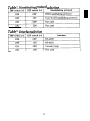
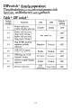
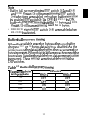
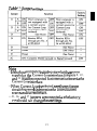
1
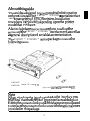
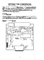
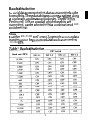
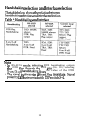
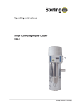
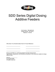
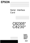
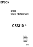
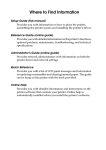
EPSON
32KB
Serial Interface Card
C82307 *
C823088 *
English
Deutsch
Français
Español
Italiano
4000273
C01-00
FCC COMPLIANCE STATEMENT
FOR AMERICAN USERS
This equipment has been tested and found to comply with the limits for a Class B digital
device, pursuant to Part 15 of the FCC Rules. These limits are designed to provide
reasonable protection against harmful interference in a residential installation. This
equipment generates, uses, and can radiate radio frequency energy and, if not installed
and used in accordance with the instructions, may cause harmful interference to radio
communications However. there is no guarantee that interference will not occur in a
particular installation. If this equipment does cause harmful interference to radio or
television reception, which can be determined by turning the equipment off and on, the
user is encouraged to try to correct the interference by one or more of the following
measures:
— Reorient or relocate the receiving antenna
— Increase the separation between the equipment and receiver.
— Connect the equipment into an outlet on a circuit different from that to which the
receiver is connected.
— Consult the dealer or an experienced radio/TV technician for help
This device complies with Part 15 of the FCC Rules. Operation is subject to the following
two conditions:
(1) this device may not cause harmful interference, and
(2) this device must accept any interference received,
including interference that may cause undesired operation.
FOR CANADIAN USERS
This digital apparatus does not exceed the Class B limits for radio noise emissions from
digital apparatus as set out in the radio interference regulations of the Canadian
Department of Communications
Le présent appareil numérique n´émet pas de bruits radioélectriques dépassant les limites
applicables aux appareils numériques de Class B prescrites dans le règlement sur le
brouillage radioélectrique édicté par le Ministére des Communications du Canada.
WARNING
The connection of a non-shielded printer interface cable to this printer will invalidate
the FCC Certification of this device and may cause interference levels which exceed the
limits established by the FCC for this equipment If this equipment has more than one
interface connector. do not leave cables connected to unused interfaces.
Seiko Epson Corporation shall not be liable against any damages or problems arising
from the use of any options or any consumable products other than those designated
as Original Epson Products or Epson Approved Products by Seiko Epson Corporation
NOTICE
All rights reserved. Reproduction of any part of this manual in any form
without Seiko Epson’s express written permission is forbidden.
The contents of this manual are subject to change without notice.
All efforts have been made to ensure the accuracy of this manual. However,
errors be detected, Seiko Epson would greatly appreciate being informed
The above notwithstanding, Seiko Epson can assume no responsibility for
in this manual or their consequences
Copyright © 1990 by Seiko Epson Corporation, Nagano. Japan
whatsoever
should any
of them.
any errors
32KB Serial Interface Card
C82307* / C82308*
English
32-KB-Schnittstellenkarte
C82307* / C82308*
Deutsch
Carte d´Interface série 32Ko
C82307* / C82308*
Français
Módulo de interface en serie de 32KB
C82307* / C82308*
Español
Scheda dell´interfaccia seriale da 32KB
C82307* / C82308*
Italiano
TABLE OF CONTENTS
SETTING THE CONDITIONS
Card layout
DIP-switch and jumper settings
DIP switches
Jumpers
2
3
4
4
5
5
14
DATA ENTRY
Serial communication
About data entry
Handshaking protocol
16
16
16
17
SELF TEST
Loopback mode
Line-monitor mode
21
21
22
SPECIFICATIONS
23
HARDWARE DESCRIPTION
25
CIRCUIT DIAGRAMS
28
INSTALLATION
31
INTRODUCTION
About this guide
INTRODUCTION
The Serial Interface Card C82307 * /C82308 * is an interface
that allows asynchronous serial data communication
between a host computer and an EPSON printer.
This interface card offers the following features:
• A 32K byte buffer that frees up your computer for
other uses while your printer continues to print
• Two self-test functions that can help solve interface
problems
• Data transmission that can be set at either RS-232D,
RS-422A, or 20-mA Current-Loop levels (RS-232D
has been revised from the former RS-232C. Set the
signal levels for RS-232D the same as for RS-232C.)
• Handshaking protocol using X-on/X-off or DTR flag
control
• Selectable data word structure that allows you to
choose parity (Odd, Even, None, or Ignore) and
word bit settings (either 7 or 8 bit)
•
Selection of baud-rate settings from 75 to 38,400 BPS
(Data transmission speed is limited to 19,200 BPS
when interface is set to either RS-232D or 20-mA
Current-Loop.)
• DIP-switch 1 settings that you can change even after
installation
About this guide
This guide is designed to give you detailed information
on how to install your C82307 * /C82308 * serial interface
card in a variety of EPSON printers. Installation
procedures vary slightly depending upon the printer
model that you have.
Also included are instructions on how to adjust the
settings of the C82307 * /C82308 * interface card, as well as
a general description of serial data communication.
The C82307 * /C82308 * option package contains the
following items:
C82307*
C82308*
serial I/F card (1)
O p t i o n a l connector lock nuts (2)
Note
When attaching the interface cable to the interface, you
may find that the screws of your interface cable do not
fit into the connector lock nuts. If this happens you will need
to replace the connector lock nuts with the optional ones
provided in this package.
3
SETTING THE CONDITIONS
The C82307 * /C82308 * interface card has three sets of
DIP (Dual In-line Package) switches, and eight jumpers.
These switches and jumpers are used for selecting
various interface operations.
Card layout
The figure below shows the layout of the C82307 * KS2308 *
card, and the locations of the DIP switches and jumpers.
Figure 1. Card layout
4
DIP switch and jumper settings
Before you install the C82307* /C82308* interface, you
may need to adjust the DIP-switch 2, DIP-switch 3, and
jumper settings. You can change the DIP-switch 1
settings after you install the interface. When making
DIP-switch setting changes, it is best to use a pointed
device, such as a ball-point pen or small screwdriver.
Caution
All changes of DIP-switch and jumper settings should be
made with the printer power turned off. New settings
become valid only when the printer is turned on.
DIP switches
The settings on DIP switches allow you to change
interface functions. The three sets of DIP switches on
the C82307* /C82308* are labelled SWl, SW2, and
SW3. Each set contains a number of individual toggletype switches that can be set either on or off. The
individual switches are referred to by set (SW1, SW2, or
SW3) and number. Therefore, the switch in set SW1
marked by the small number 3 is called DIP switchl-3.
5
DIP switch 1 (interface operations)
The tables below contain information on switch
functions, and the factory setting of each.
Table 1. DIP switch 1
Note
Some printers have a selecting switch (or function) that
allows you to select between the optional and original
interfaces. If you install the interface card in this type of
printer, you should set DIP switch 1-l on the interface
card to ON and also change the setting in the printer to
select the optional interface.
6
Data word structure
The data word structure is also operator selectable
through DIP-switch settings (See Table 1). The word
structure for serial data is:
1 start bit +7 or 8 data bits (selectable) + 1 parity
bit (selectable) + l or more stop bits.
The table below shows the possible word structure
combinations.
Table 2. Word structure
You can select the parity check method with DIP-switch
settings (See Table 3).
Table 3. Parity check
7
DIP switch 2 (interface operations)
The tables below contain information on switch
functions, and the factory setting of each.
Table 4. DIP switch 2
8
Baud rate selection
In serial data communication, data is transmitted in the
form of bits. These data bits go out one at a time along
a single path, and in a specified order. The BPS (Bits
Per Second) rate, or speed at which these bits are
transmitted, can be selected using a combination of DIPswitch settings.
Note
In either RS-232D or Current-Loop mode, accurate data
transfer cannot be guaranteed at a baud rate exceeding
19,200 BPS.
Table 5. Baud rate selection
9
Handshaking selection and Interface selection
The table below shows the relation between
handshaking selection and interface selection.
Table 6. Handshaking and interface
Note
• In RS-422A mode, selecting DTR handshaking outputs
the DTR flag through the DTR pin (No. 20); selecting
X-on/X-off handshaking, fixes the value of the DTR
• The signal is always in a fixed, flag reset state. Signal
polarity can be inverted with DIP switch 3-4.
10
Table 7. Handshaking protocol selection
Table 8. Interface selection
11
DIP switch 3 (Interface operation)
The tables below contain information on switch
functions, and the factory setting of each.
Table 9. DIP switch 3
12
Note
• Buffer full recovery timing (DIP switch 3-2 and 3-3)
and DTR flag set/X-off transmit timing (DIP switch
3-6) selections are enabled only when buffer operation
is enabled (DIP switch 3-1 is OFF). If SW3-1 is ON,
buffer full recovery timing is set to 32 bytes and DTR
flag set/X-off transmit timing is set to 16 bytes.
• DSR/DCD signals (DIP switch 3-5) are enabled when
RS-232D is selected.
Buffer full recovery timing
When the available space for bytes in the print buffer
drops to 512 or 16 bytes, data entry is disabled. As the
printer prints the data in the buffer, the vacant area for
bytes increases. When this vacant area reaches one of the
four values listed in the table below, data communication
is resumed. These settings are selectable by using the
DIP switches.
Table 10. Buffer full recovery timing
Vacant area for bytes
in the print buffer
DIP switch
SW 3-2
SW 3-3
768
OFF
OFF
1024
OFF
ON
2048
ON
OFF
4096
ON
ON
13
Jumpers
The jumper is a small terminal used for connecting or
disconnecting a circuit. The jumper is on when the
jumper plug covers both wires of the terminal. Jumper
settings can be changed by either attaching or removing
the rectangular jumper plug. If the jumper is to be
turned off, connect it to just one of the two terminal
pins as shown in the figure below. By doing this, you
can avoid losing the unused jumper plug.
Figure 2. Jumpers
14
Table 11. Jumper settings
Note
• If the host computer is not equipped with a power
supply for the Current-Loop interface, jumpers Jl, J2,
and J3 must be connected for communications via the
Current-Loop interface.
• When Current-Loop is selected, see the section on
circuit diagrams to determine the correct current
source and current return.
• J5, J6, and J7 jumpers are connected at the factory;
you should not change these settings.
15
DATA ENTRY
This section gives a brief description of serial data
communication conditions and handshaking protocols
supported by the C82307* /C82308* interface card.
Serial data communications
The C82307* /C82308* interface allows you to select
either RS-232D, RS-422A, or 20-mA Current-Loop signal
levels for data communication.
This interface card also provides for either DTR (Data
Terminal Ready) or X-on/X-off handshaking protocol.
About data entry
To accommodate data entry, the C82307* /C82308*
interface card is equipped with a buffer that temporarily
stores data before transferring it to the printer. When
this buffer becomes full, any additional transmitted data
cannot be accepted and is discarded. To prevent such
data loss, special handshaking protocols are provided to
regulate the flow of data transmission. The two protocols
available on the C82307* /C82308* interface card are
DTR and X-on/X-off.
To enable data entry to the buffer while RS-232D is
selected, DSR and DCD must be held at the positive
EIA RS-232D level (SPACE) or DIP switch 3-5 must be
OFF. When DIP switch 3-5 is ON and either DSR or
DCD is set to the negative EIA RS-232D level (MARK),
all received data will be ignored by the interface card.
Note
When a parity error occurs (if parity check is enabled),
framing or overrun errors are detected in the data received,
and data is either ignored or an asterisk( * ) is printed instead.
16
Handshaking protocol
X-on/X-off Protocol
X-on/X-off protocol is a system in which the printer
transmits a code to the computer to indicate that it
cannot accept more data, and a second code when it is
once again ready. This protocol can be performed under
either RS-232D, RS-422A, or 20-mA Current-Loop signal
levels.
The C82307* /C82308* interface card sends an X-on
(11H) code when it is ready to receive data, and an X-off
(13H) when it is busy. The X-on/X-off signals may be
transmitted from the TXD terminal (pin No. 2) at
RS-232D signal levels, through the SDA and SDB
terminals (pin No. 9, 10) at RS-422A signal levels, or
through the TTY-TXD terminal (pin No. 17) at 20-mA
Current-Loop signal levels.
After the X-on flag has been set, data can be accepted
up to the maximum capacity of the buffer.
•
Transmit timing of the X-off signal
The X-off signal is transmitted when the vacant area
for bytes in the buffer drops to flag set level.
• Data transfer after X-off signal
Data can be sent to the printer even after the X-off
signal is transmitted as long as sufficient room for
data remains in the buffer. However, if the
transmitted data exceeds the vacant area in the
buffer, it will be discarded. The X-off character will
be transmitted again when the remaining buffer
capacity is actually 0 bytes. At that time, a BS code
(08H) and "/" character (2FH) will be sent to the
printer.
17
• Transmit timing of the X-on signal
The X-on signal is transmitted when the power is first
turned on, and when the vacant area in the buffer is
greater than the preset value of the buffer recovery
timing. Refer to Table 12 for information on flag
set/reset conditions.
Figure 3. X-on/X-off timing
X-ON
POWER ON
X-OFF
Buffer
capacity: 512
or 16 bytes
X-OFF
Buffer
capacity
0 byte
X-ON
Buffer capacity
specified with
DIP switches
3-2 and 3-3.
DTR protocol
This interface card also provides for DTR handshaking
protocol using either RS-232D, RS-422A, or CurrentLoop signal levels.
Under this system, when the printer is turned on the
DTR enters the SPACE state, meaning that data entry is
enabled. When the rate of data reception is greater than
that of printing, the buffer gradually fills up. Once the
vacant area for transmitted bytes drops to flag set level,
the DTR sets the status flag to prohibit further data
entry. This flag is output through the DTR (pin No. 20)
under RS-232D signal levels, through the TRA and TRB
(pin No. 11, 13) under RS-422A signal levels, and through
the TTY-TXD (pin No. 17) under Current-Loop levels.
18
With the status flag set and data reception prohibited,
the vacant area of the buffer gradually increases as the
printer continues to print. When the vacant area for
bytes reaches the preset recovery value (see Table 12),
the flag is reset and data entry is again enabled.
Buffer Operation Disabled
Under this condition, the flag is output from the DTR
(pin No. 20) in the case of RS-232D, from the TRA and
TRB (pin No. 11, 13) in the case of RS-422A, and from
the TTY-TXD (pin No. 17) in the case of Current Loop.
When DIP switch 3-l is ON (buffer is disabled), flag set
timing is set to 16 bytes and flag reset timing is set to 32
bytes.
Table 12. Flag set/reset conditions
DTR Handshaking
X-on/X-off handshaking
Flag is set
RS-232D: negative EIA
(not ready to level
RS-422A: negative EIA
accept data)
level
TRA-TRB,
TRA: inverted
TRB: noninverted
20-mA Current Loop: low
impedance (Current on)
Transmitting X-off
character
Flag is reset
(ready to
accept data)
Transmitting X-on
character
RS-232D: positive EIA
level
RS-422A: positive EIA
level
TRA-TRB
TRA: inverted
TRB: noninverted
20-mA Current Loop: high
impedance (Current off)
19
Flag set timing is selectable with DIP switch 3-6, and
flag reset timing is selectable with DIP switches 3-2 and
3-3.
Printer status error
The flag is set immediately, regardless of the remaining
buffer capacity, if the printer detects an error.
20
SELF TEST
Two self-test modes can be selected by DIP switches 3-7
and 3-8. To select a self-test mode, first turn off the
power to the printer and then change the DIP-switch
setting. When the power is turned back on, the new
settings automatically go into effect. To exit from the
self test, turn off power and reset the DIP switches.
Table 13. Self-test modes
Mode
SW 3-7
SW 3-8
ON
OFF
Loopback
ON
ON
Line monitor
Loopback mode
Turning the power on during loopback mode causes the
interface card to first check the RAM, and then print
the RAM capacity and DIP-switch settings. The interface
then sends the character codes 30H to 39H, followed by a
line feed command (0AH), to the printer eight times.
See Table 14. for the terminal pin connections necessary
with your selected interface type.
Table 14. Terminal pin connections
Interface
selection
Transmitting terminal pin/
Receiving terminal pin
RS-232D
Pin No. 2 (TXD) ........................ Pin NO. 3 (RXD)
RS-422A
Pin No. 9 (SDA) ......................... Pin No. 16 (RDA)
Pin No. 10 (SDB) ............................. Pin No. 18 (RDB)
Current Loop
Pin No. 17 (TTY-TXD) ....................... Pin No. 25 (TTY-RXD)
Pin No. 24 (TTY-TXD Return) ............................... Pin No. 23
(TTY-RXD Return)
l In this case, the jumper must be set as follows: J1-A
is ON, J2-A is ON, and J3 is ON
21
Line-monitor
mode
During this test, data on the RS-232D line, RS-422A
line, or Current-Loop line is printed in hexadecimal
code. The only difference between normal operation and
this mode is that all data is converted into hexadecimal
form.
22
SPECIFICATIONS
1. Synchronization:
Asynchronous
2. Baud Rate: RS-232D: 75, 110, 134.5, 150, 200, 300,
600, 1,200, 1,800, 2,400, 4,800,
9,600, or 19,200 BPS (selectable)
RS-422A: 75, 110, 134.5, 150, 200, 300,
600, 1,200, 1,800, 2,400, 4,800,
9,600, 19,200, or 38,400 BPS
(selectable)
Current Loop: 75, 110, 134.5, 150, 200,
300, 600, 1,200, 1,800, 2,400,
4,800, 9,600, or 19,200 BPS
(selectable)
3. Word length:
Start bit: 1 bit
Data bit: 7 or 8 bits (selectable)
Parity bit: Odd, even, none, or ignore (selectable)
Stop bit: 1 bit or more
4. Input signal polarity:
1) RS-232D:
MARK = logic "l" ( - 3 to - 25V)
SPACE = logic "0" ( + 3 to + 25V)
2) RS-422A:
MARK = logic "1"
The RDA is negative (-0.2 V to -6 V)
with respect to the RDB.
SPACE = logic "0"
The RDB is positive (+0.2 V to +6 V)
with respect to the RDB.
R D A : Inverted R D B : Noninverted
3) Current loop:
MARK = logic "1" (Current on)
SPACE = logic "0" (Current off)
23
5 . Handshaking
Table 15. Handshaking
Using DTR
protocol
Using X-on/X-off
protocol
RS-232D
The signal at pin No. 20 is Data transmitted from pin
as follows;
No. 2 is controlled as
MARK-data transfer
follows;
disabled
X-on (11H)—data transfer
SPACE-data transfer
enabled
enabled
X-off (13H)—data transfer
disabled
(Signal polarity can be
inverted by DIP-switch
setting.)
RS-422A
The signal at pin No. 11
with respect to pin No. 13
is:
MARK-data transfer
disabled
SPACE-data transfer
enabled
(Signal polarity can be
inverted by DIP switch
setting.)
Data transmitted by the
differential voltage of pin
No. 9 to pin No. 10 is
controlled as follows:
X-on (11H)—data transfer
enabled
X-off (13H)—data transfer
disabled
Current Loop The impedance between
Data transmitted by the
pin No. 17 and pin No. 24 change of the impedance
is as follows;
between pin No. 17 and
LOW (MARK)—data
pin No. 24 is controlled as
follows;
transfer disabled
HIGH (SPACE)-data
X-on (11H)—data transfer
transfer enabled
enabled
(Signal polarity can be
X-off (13H)—data transfer
inverted by DIP-switch
disabled
setting.)
24
HARDWARE DESCRIPTION
1. I/F board connector: EIA standard 25-pin D-SUB
female connector.
2. For signal description and pin assignment, refer to
the table below:
Table 16. Signal Description and Pin Assignment
25
26
Note
The column heading “Direction” refers to the direction of
signal flow as viewed from the printer.
27
CIRCUIT DIAGRAMS
RS-232D Transmitter/Receiver Circuit Diagrams
Figure 4. Transmitter Circuit Diagram
l/3 MC145407
TXD
From TXD
l/3 MC145407
DTR
From DTR
Figure 5. Receiver Circuit Diagram
1/3 MC145407
RXD
To RXD
28
RS-422A Transmitter/Receiver Circuit Diagrams
Figure 6. Transmitter Circuit Diagram
Figure 7. Receiver Circuit Diagram
29
Current-Loop Transmitter/Receiver Circuit Diagrams
Figure 8. Transmitter Circuit Diagram
Figure 9. Receiver Circuit Diagram
Note
Set Jumpers J1, J2, and J3 referring these diagrams.
30
INSTALLATION
The C82307* /C82308* interface card is designed to be
installed inside the printer. Installation or removal of the
interface card is easy, and requires only a screwdriver.
The following section gives you detailed information on
how to install your interface card in a variety of
EPSON printers.
Caution
• Turn off the power to the printer and the computer
before installing the interface card. Make sure that all
power and interface cables are removed.
• Avoid touching the printer’s circuit board contacts, as
many of these components are sensitive to static
electric charges that may build up on your body.
1. First, adjust DIP switches and jumpers settings, as
necessary.
If the screws don’t fit your interface cable, you will
need to replace the connector lock nuts with the
optional ones provided in this package.
Note
The original C82307* lock nuts are imperial standard
(inch), and the C82308* lock nuts are metric.
31
2. Fit both sides of this interface card into the guides
inside the compartment.
3. Insert this interface card until the interface pins mate
with the connector inside your printer.
4. Secure the interface with the two screws.
32
EPSON OVERSEAS MARKETING LOCATIONS
EPSON AMERICA, INC.
2780 Lomlta Blvd.,
Torrance. Calif. 90505. U.S.A
Phone: (213) 539-9140
Fax: (213) 534-5854
EPSON DEUTSCHLAND GmbH
Zülpicher Straße, 4000 Düsseldorf 11
F.R. Germany
Phone: (0211) 56030
Telex: 8584786
EPSON UK LTD.
Campus 100, Maylands Avenue.
Hemel Hempstead, Herts,
HP2 7EZ, U.K.
Phone: 442-61144
Telex: 5162467
EPSON FRANCE S. A.
68 bis, rue Marjolin 92300,
Levallois-Perret, France
Phone: (1) 47-373333
Telex: 610657
EPSON AUSTRALIA PTY. LTD.
Unit 3, 17 Rodborough Road,
Frenchs Forest. NSW 2086 Australia
Phone: (2) 452-0666
Fax: (2) 975-1409
EPSON SINGAPORE PTE. LTD.
No. 1 Raffles Place #26-00
OUB Centre, Singapore 0104
Phone: 5330477
Fax: 5338119
EPSON HONG KONG LTD.
25/F, Harbour Centre.
25 Harbour Road Wanchai,
Hong Kong
Phone: 8314600
Telex: 65542
EPSON ELECTRONICS TRADING LTD.
(TAIWAN BRANCH)
10F, No. 287 Nanking E. Road, Sec. 3,
Taipei, Taiwan, R.O.C.
Phone: (02) 717-7360
Fax: (02) 712-9164
EPSON ITALIA S.p.A.
V, le F, lli Casiraghi, 427 20099
SESTO S, GIOVANNI MI, Italy
Phone: 2-262331
Fax: 2-2440750
EPSON IBERICA, S.A.
Paris, 152, 08036 Barcelona Spain
Phone: 410-34-00
Fax: 439-95-17
SEIKO EPSON CORPORATION
(Hirooka Office)
80 Harashinden, Hirooka
Shiojiri-shi, Nagano-ken
399-07 Japan
Phone: (0263) 52-2552
1990 May