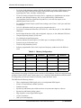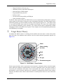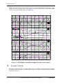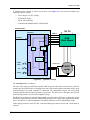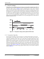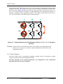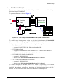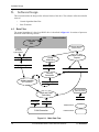
1
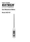
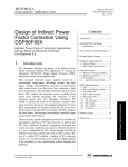
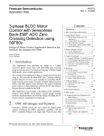
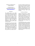
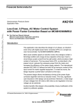
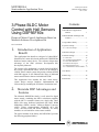
MOTOROLA
Order by AN1916/D
(Motorola Order Number)
Rev. 0, 6/01
Semiconductor Application Note
3-Phase BLDC Motor
Control with Hall Sensors
Using DSP56F80x
Design of Motor Control Application Based on
Motorola Software Development Kit
Contents
1. Introduction of Application
Benefit
1
2. Motorola DSP Advantages and
Features .....................................1
3. Target Motor Theory ......................3
Pavel Grasblum
4. System Concept.............................. 4
Introduction of Application
Benefit
This Application Note describes a design of a 3-phase BLDC
(Brushless DC) motor drive based on Motorola’s DSP56F80x
dedicated motor control device. The software design takes
advantage of the SDK (Software Development Kit)
developed by Motorola.
The concept of the application is a speed closed loop BLDC
drive using a position Hall Sensor. It serves as an example of
a BLDC motor control system design using a Motorola DSP
with SDK support. It also illustrates the usage of dedicated
motor control libraries that are included in the SDK.
This Application Note includes the basic motor theory,
system design concept, hardware implementation and
software design, including the PC Master visualization tool.
2.
Motorola DSP Advantages and
Features
The Motorola DSP56F80x family is well suited for digital
motor control, combining the DSP’s calculation capability
with the MCU’s controller features on a single chip. These
DSPs offer many dedicated peripherals like Pulse Width
Modulation (PWM) module, Analog-to-Digital Converter
(ADC), Timers, communication peripherals (SCI, SPI,
CAN), on-board Flash and RAM. Generally, all family
members are well suited for various motor controls.
The typical member of the family, the DSP56F805, provides
the following peripheral blocks:
© Motorola, Inc., 2001
5. Hardware Design ............................9
6. Software Design ...........................10
6.1
6.2
6.3
6.4
6.5
6.6
Data Flow ......................................10
Application State Diagram............11
Drive State Machine......................13
Routines Description.....................13
Implementation Notes ...................17
Communication with PC Master...17
7. PC Master .....................................18
8. DSP Usage ...................................18
9. References ....................................19
3-Phase BLDC Motor Control
with Hall Sensors
1.
4.1 Control Technique...........................6
Motorola DSP Advantages and Features
•
Two Pulse Width Modulator modules (PWMA & PWMB), each with six PWM outputs, three
Current Sense inputs, and four Fault inputs, fault tolerant design with deadtime insertion,
supporting both Center- and Edge- aligned modes
•
Twelve bit Analog to Digital Convertors (ADCs), supporting two simultaneous conversions
with dual 4-pin multiplexed inputs; ADC can be synchronized by PWM modules
•
Two Quadrature Decoders (Quad Dec0 & Quad Dec1), each with four inputs, or two
additional Quad Timers A & B
•
Two dedicated General Purpose Quad Timers totaling 6 pins: Timer C with 2 pins and Timer
D with 4 pins
•
CAN 2.0 A/B Module with 2-pin ports used to transmit and receive
•
Two Serial Communication Interfaces (SCI0 & SCI1), each with two pins, or four additional
GPIO lines
•
Serial Peripheral Interface (SPI), with configurable 4-pin port, or four additional GPIO lines
•
Computer Operating Properly (COP) timer
•
Two dedicated external interrupt pins
•
Fourteen dedicated General Purpose I/O (GPIO) pins, 18 multiplexed GPIO pins
•
External reset pin for hardware reset
•
JTAG/On-Chip Emulation (OnCE)
•
Software-programmable, Phase Lock Loop-based frequency synthesizer for the DSP core
clock
Table 2-1. Memory Configuration
DSP56F801
DSP56F803
DSP56F805
DSP56F807
Program Flash
8188 x 16-bit
32252 x 16-bit
32252 x 16-bit
61436 x 16-bit
Data Flash
2K x 16-bit
4K x 16-bit
4K x 16-bit
8K x 16-bit
Program RAM
1K x 16-bit
512 x 16-bit
512 x 16-bit
2K x 16-bit
Data RAM
1K x 16-bit
2K x 16-bit
2K x 16-bit
4K x 16-bit
Boot Flash
2K x 16-bit
2K x 16-bit
2K x16-bit
2K x 16-bit
Other than the fast Analog-to-Digital converter and the 16-bit Quadrature Timers, the most interesting
peripheral from the BLDC motor control point of view is the Pulse Width Modulation (PWM) module.
Its configuration provides the freedom to efficiently control the BLDC motor.
The PWM has the following features:
2
•
Three complementary PWM signal pairs, or six independent PWM signals
•
Features of complementary channel operation
•
Deadtime insertion
•
Separate top and bottom pulse width correction via current status inputs or software
•
Separate top and bottom polarity control
•
Edge-aligned or center-aligned PWM signals
•
15-bits of resolution
•
Half-cycle reload capability
3-Phase BLDC Motor Control with Hall Sensors
Target Motor Theory
•
Integral reload rates from one to 16
•
Individual software-controlled PWM outputs
•
Mask and Swap of PWM outputs
•
Programmable fault protection
•
Polarity control
•
20-mA current sink capability on PWM pins
•
Write-protectable registers
The BLDC motor control utilizes the PWM block set in the complementary PWM mode to generate
control signals for all switches of the power stage with deadtime generation. The PWM outputs can be
controlled separately by software which can set the control signal to logical 0 or 1. One feature which
is very useful for BLDC motor control is the channel swap function. The state of the control signals
can be changed immediately when required by the motor position (phase commutation) without
changing the content of the PWM value registers. These changes can be accomplished asynchronously
to the PWM duty cycle update.
3.
Target Motor Theory
A brushless DC (BLDC) motor is a rotating electric machine where the stator is a classic three phase
stator like that of an induction motor and the rotor has surface-mounted permanent magnets (see
Figure 3-1).
Stator
Stator winding
(in slots)
Shaft
Rotor
Air gap
Permanent magnets
Figure 3-1. BLDC Motor - Cross Section
In this respect the BLDC motor is equivalent to an inverted DC commutator motor, in that the magnet
rotates while the conductors remain stationary. In the DC commutator motor, the current polarity is
reversed by the commutator and brushes, but in the brushless DC motor, the polarity reversal is
performed by a power transistor which must be switched in synchronization with the rotor position.
Therefore, the BLDC motor often has either internal or external position sensors to sense actual rotor
position.
3-Phase BLDC Motor Control with Hall Sensors
3
System Concept
The presented application uses three Hall Sensors to sense actual position. The Hall Sensors’ signals
together give the six output values. These outputs are read by DSP and the corresponding output
voltage is generated by PWM outputs (see Figure 3-2).
Phase Magnetic Flux Linkage
3VLB$
3VLB%
3VLB&
Ph. A Ph. B
Ph. C
Ph. B
$WRS %WRS &WRS
&ERW $ERW
8LB$
Phase Back EMF
Ph. A
8LB%
8LB&
Speed reversal
Ph. C
%ERW
Acting power switch in the power stage
Phase-Phase Back EMF
A-B
8LB$%
8LB$%
8LB%&
8LB%&
8LB&$
8LB&$
B-C
C-A
3RVB$
Phase C
Hall Sensor outputs
3RVB%
3RVB&
Phase B
ABC
[101]
Phase A
Figure 3-2. BLDC Motor - Back EMF and Mag. Flux, Hall Sensor Outputs
4.
System Concept
The system is designed to drive a 3-phase BLDC motor. The DSP runs the main control algorithm.
According to the user interface input and feedback signals, it generates 3-phase PWM output signals
for the motor inverter.
4
3-Phase BLDC Motor Control with Hall Sensors
System Concept
A standard system concept is chosen for the drive (see Figure 4-1). The system incorporates the
following hardware boards:
•
Power Supply 12V DC, 4Amps
•
EVM Motor Board
•
BLDC Motor IB23810
•
Evaluation Board DSP56F803 or DSP56F805
DSP56F80x EVM
12V DC
DSP56F80x
PWM1-6
PC Master
R
S
2
3
2
P
W
M
Speed
Calculation
PI
Controller
Commutation
Handler
START
STOP
UP
G
P
I
O
±ΩReq
DOWN
EVM
Motor Board
T
I
M
E
R
D
E
C
O
D
E
R
Hall Sensors
BLDC
motor
Figure 4-1. System Concept
The control process is as follows:
The state of the inputs is periodically scanned, while the speed of the motor is measured on each new
coming edge from Hall Sensors. According to the state of the control signals (Start/Stop switch, speed
up/down buttons) the speed command is calculated. The comparison between the actual speed
command and the measured speed generates a speed error. The speed error is brought to the speed PI
controller that generates a new corrected applied voltage.
The Hall Sensor signals are scanned independently on speed control. Each new coming edge of any
Hall Sensor signal calls the interrupt routine which calculates new voltage shape applied to the BLDC
motor. This process is called commutation. The PWM transistors work in complementary mode.
Undervoltage protection of the DC Bus is measured during the control process and is performed by
software.
3-Phase BLDC Motor Control with Hall Sensors
5
System Concept
4.1 Control Technique
The brushless DC motor (BLDC motor) is also known as an electronically commuted motor. There are
no brushes on the rotor and the commutation is performed electronically at certain rotor positions. The
three phase voltage system (see Figure 4-2) with a rectangular shape is used to create a rotational
torque. This easily created shape of applied voltage ensures the simplicity of control of drive. The rotor
position must be known in order to align energized phases with the rotor’s permanent magnetic field.
The alignment is very important because it results in proper commutation in the PWM inverter where
the voltage level is reduced by chopping. In this condition the motor behaves as a DC motor and runs
at the best working point. The simplicity of control and good performance makes this motor a natural
choice for low-cost and high-efficiency applications. There are many methods how to provide
alignment between back EMF and commutation events. The presented application use Hall Sensors to
sense the commutation events.
electrical
angle
Figure 4-2. Three phase voltage system applied to BLDC motor
4.1.1 Commutation Algorithm
The commutation algorithm provides the generation of a rotational field according to rotor position.
This algorithm uses the Hall Sensors to obtain the rotor position. The Hall sensors outputs are
connected to Quadrature decoder input pins. The input pins go through the digital filter to three
quadrature timers. The timers are set to catch each edge of input signals and call interrupt routine
which provide commutation algorithm. The Hall Sensor consists of three sensors (Sensor A, Sensor B,
Sensor C). These sensors comprise six states (001, 010, 011, 100, 101, 110). Each state determines
which phases should be powered by the 3-phase inverter. The interrupt routine reads the state of Hall
Sensors from Input Monitor Register (IMR) of quadrature decoder. This value is used as pointer to the
commutation table (Table 4-1, Table 4-2), which includes information about masking and swapping
of power transistors. The resultant voltage applied to BLDC motor per one electrical revolution is
shown on Figure 4-2.
6
3-Phase BLDC Motor Control with Hall Sensors
System Concept
Table 4-1. Commutation Sequence for Clockwise Rotation
+DOO6HQVRU$
+DOO6HQVRU%
+DOO6HQVRU&
3KDVH$
3KDVH%
3KDVH&
9'&%
9'&%
1&
9'&%
1&
9 '&%
1&
9 '&%
9 '&%
9 '&%
9 '&%
1&
9 '&%
1&
9'&%
1&
9'&%
9'&%
Table 4-2. Commutation Sequence for Counterclockwise Rotation
+DOO6HQVRU$
+DOO6HQVRU%
+DOO6HQVRU&
3KDVH$
9'&%
3KDVH%
9'&%
3KDVH&
1&
1&
9'&%
9'&%
9'&%
1&
9'&%
9'&%
9'&%
1&
9'&%
1&
9'&%
9'&%
9'&%
1&
Start of New Edge
Interrupt
Read new state
of Hall Sensors
Look up new swap
and mask values
in the table
Put new value
to PWM module
RTI
Figure 4-3. Commutation Algorithm for Hall Sensors
3-Phase BLDC Motor Control with Hall Sensors
7
System Concept
The generation of the PWM voltage waveforms is done by using of masking and swapping without
changing of the PWM Value Register (duty cycle). This method allows independence of commutation
and speed control. Figure 4-4 shows the generated voltage waveforms for Hall Sensors state A=0,
B=1, C=0 at clockwise direction. The phase A is masked (disabled). The voltage polarity of phase C is
changed by swapping of upper and bottom transistor. The resulting voltage applied on the motor is
UBC. The Value Registers of all PWM outputs remain unchanged.
A
B
70%
0%
1.
0%
3.
30%
2.
4.
C
70%
30%
5.
30%
70%
6.
SWAP
Figure 4-4. Voltage Waveforms for the Hall Sensors State A = 0, B = 1, C = 0, Clockwise
Direction
Warning: For the 56F80x revision B the mask feature works properly in the independent mode.
Therefore it is necessary to use software control to implement the mask feature in the
complementary mode.
4.1.2 Speed Control
The speed of BLDC motor is controlled by amplitude of applied voltage. The amplitude of applied
voltage is regulated by pulse-width modulation (PWM).
The main advantage of the described application is the independence of the commutation
algorithm and the speed control algorithm.
8
3-Phase BLDC Motor Control with Hall Sensors
Hardware Design
5.
Hardware Design
The motor control system is designed to drive the 3-phase BLDC motor in a speed closed loop on
EVM Motor Board (ECMTREVAL).
The system configuration is shown in Figure 5-1.
ZIODW
8
*1'
-
9'&
ULEERQ
FDEOH
(YDOXDWLRQ
0RWRU
%RDUG
8
&RQWUROOHU%RDUG
-
'63)[(90
-
+DOO6HQVRU&RQQ7DEOH
0RWRU
&RQWUROOHU
(&075(9$/
0
&RQQ
'63)
-
'63)
-
'63)
-
81,&RQQHFWRUV7DEOH
&RQWUROOHU
IB23810
+DOO6HQVRUV&DEOH
&RQQ
'63)
3
'63)
-
'63)
-
Figure 5-1. Low Voltage Evaluation Motor HW System Configuration
The detailed setup including jumper settings can be found in the document Embedded SDK
(Software Development Kit) Targeting Motorola DSP5680X Platform (where X means 3 or 5).
All the system parts are supplied and documented according the following references:
•
M1 - IB23810 Motor
— supplied in kit ECMTREVAL - Evaluation Motor Board Kit
•
U2 EVM Motor Board:
— supplied in kit with IB23810 Motor: ECMTREVAL - Evaluation Motor Board Kit
— described in: Evaluation Motor Board User’s Manual
•
U1 CONTROLLER BOARD for DSP56F805:
— supplied as: DSP56805EVM
— described in: DSP Evaluation Module Hardware User’s Manual
•
or U1 CONTROLLER BOARD for DSP56F803:
— supplied as: DSP56803EVM
— described in: DSP Evaluation Module Hardware User’s Manual
The detailed description of individual boards can be found in comprehensive User’s Manuals
belonging to each board or on http://mot-sps.com/motor/devtools/index.html. The user’s manual
incorporates the schematic of the board, descriptions of individual function blocks and bill of
materials. The individual boards can be ordered from Motorola as a standard product.
3-Phase BLDC Motor Control with Hall Sensors
9
Software Design
6.
Software Design
This section describes the design of the software blocks of the drive. The software will be described in
terms of:
•
Control Algorithm Data Flow
•
State Transition
6.1 Data Flow
The control algorithm of a close loop BLDC drive is described in Figure 6-1. It consists of processes
described in the following sections.
SCI
Communication
Process
SCI
POSITION SENSOR
(Hall Sensors)
SPEED
SETTING
by BUTTONS
Latest Position
Capture
Period
omega_required_mech
Measuring
omega_desired_mech
MeasuredTime
DirectionSpinning
EncoderState
Velocity
Calculation
Speed Controller
(PI Controller)
omega_actual_mech
DC_Bus Voltage
(A/D Converter)
Mask and Swap
Calculation
u_dc_bus
DesVoltage
PWMState
Software Block
PWM Generation
Hardware Block
Figure 6-1. Main Data Flow
10
3-Phase BLDC Motor Control with Hall Sensors
Software Design
6.1.1 Processes Latest Position Capture, Period Measuring and
Velocity Calculation
The Latest Position Capture, Period Measuring and Velocity Calculation processes relate to the inputs
of the Hall Sensors. The sensors generate streams of pulses that are captured (separately for each
sensor) by the Input Capture (IC) function.
The process Latest Position Capture captures the latest state of Hall Sensors.
The processes Period Measuring and Velocity Calculation read the time between the adjacent rising
edges of Hall sensor output and calculates the actual motor speed omega_actual_mech.
6.1.2 Process Speed Controller
The process calculates the duty cycle of the PWM based on the output of the speed controller (the PI
controller).
6.1.3 Process Mask and Swap Calculation
The process calculates which PWM channel is enabled for PWM generation and which phase is
swapped.
6.2 Application State Diagram
Reset
Initialization
Interrupts
Main loop
(State Machine)
Figure 6-2. Application State Diagram
As Figure 6-2 shows, the application state consists of the initialization routine, followed by main loop
with background tasks. The time critical functions are calculated by the interrupt routines.
3-Phase BLDC Motor Control with Hall Sensors
11
Software Design
The brief description of the 3-ph BLDC motor control follows:
•
Initialization Routine (entered after RESET):
— ADC initialization
— System Timer for LED initialization
— PWM initialization
— IRQA and IRQB interrupt initialization
— Quadrature timers A0, A1, A2 and their interrupt initialization
— Quadrature decoder initialization
— getting of initial motor position
— setting of PI controller parameters
— quadrature timer A3 initialization for speed measuring
•
Main Loop
— Application state machine
— - check of START/STOP switch state
— - check of DC bus voltage
•
System Timer Interrupt Handler
— UP/DOWN buttons filter
— LED blinking and lighting
— DC bus voltage measuring
— Speed calculation
— Speed PI controller calculation
— setting of new duty cycle to PWM
•
IRQA Interrupt Handler
— decrement required speed
•
IRQB Interrupt Handler
— increment required speed
•
IC (Input Capture) Interrupt Handler (QTimers A0, A1, A2)
— reading of encoder state
— spin direction calculation
— mask and swap of PWM transistors calculation
— setting of new mask and swap to PWM
•
Timer Overflow Interrupt Handler (QTimer A3) for speed measuring
— Increment overload counter
•
IC (Input Capture) Interrupt Handler (QTimer A3) for speed measuring
— calculation of non-scaled period of one Hall Sensor channel
•
SCI (Serial Communication Interface)
— Communication with PC Master
12
3-Phase BLDC Motor Control with Hall Sensors
Software Design
6.3 Drive State Machine
The drive can be in one of the following states as shown in Figure 6-3, which also shows transition
conditions among the drive states.
SwitchState=START
Reset
Init
State
SwitchState=STOP
SwitchState=STOP OR
u_dc_bus<MIN_DC_BUS_VOLTAGE
Stopped
State
Running
State
SwitchState=START AND
u_dc_bus>=MIN_DC_BUS_VOLTAGE
Figure 6-3. Drive State Machine Transitions
6.4 Routines Description
6.4.1 LedISR(void)
This interrupt routine is called periodically by timer which is set by function LedInit.
This routine executes following functions:
•
LED blinking according to application mode (START/STOP).
The period of blinking is given by LED_ISR_COUNT_VALUE x timer period (20 ms)
•
Reading of new sample of DC Bus Voltage and starting of new conversion
•
Scaling of measured period of one Hall Sensor channel
•
Speed calculation
3-Phase BLDC Motor Control with Hall Sensors
13
Software Design
The constant OMEGA_ACTUAL_MECH_CONST is given by following equations:
position difference = 1/4 rev (given by each edge of one Hall Sensor phase and two pole pairs
motor)
max. period time = 0.2 s (chosen according to required min. speed)
vmin = 60*(position difference)/(max. period time) = 75 rpm
vmax = 20*vmin = 1500 rpm (chosen according to required max. speed)
OMEGA_ACTUAL_MECH_CONST = 32767*vmin/vmax = 1638
•
Calculation of new duty cycle (by PI controller)
•
Setting of new duty cycle
6.4.2 ISRQTimer(void)
This interrupt routine is called on each edge which is captured on the timers’ input. The timers A0, A1,
A2 call the same interrupt routine.
This routine executes following functions:
•
Reading of new Hall Sensors’ state
•
Calculation of spin direction
•
Calculation of transistors mask and swap
•
Set of transistors mask and swap
6.4.3 Word 16 DirectionCalculation(Word16 EncoderState,
Word16 *NextEncoderState)
Parameters:
Word16 EncoderState - Input
Actual state of Hall sensors
Word16 *NextEncoderState - Input/Output
pointer to expected state of Hall Sensors
The function returns a value of 1 or -1 according to spin direction.
6.4.4 LedInit(void)
This function is called during initialization only and sets system timer with period 20 ms. The system
timer calls an interrupt routine named LedISR.
6.4.5 IncrementVariable (int *Variable, int Increment, int Limit)
The function increments the variable pointed to by VARIABLE by Increment up to Limit.
6.4.6 DecrementVariable (int *Variable, int Decrement, int Limit)
The function decrements the variable pointed to by VARIABLE.
14
3-Phase BLDC Motor Control with Hall Sensors
Software Design
6.4.7 UpButtonISR(void)
The interrupt function is called when the UP push button is pushed. The function increments variable
omega_required_mech by speed_increment up to speed_up_limit. If omega_required_mech is equal to
zero the omega_required_mech is directly set to minimal speed speed_400rpm
6.4.8 DownButtonISR(void)
The interrupt function is called when the DOWN push button is pushed. The function decrements
variable
omega_required_mech
by
speed_increment
up
to
speed_down_limit..
If
omega_required_mech is equal to zero the omega_required_mech is directly set to minimal speed
-speed_400rpm
6.4.9 ApplicationStateMachine(void)
SwitchState=START
Reset
Init
State
SwitchState=STOP
Stopped
State
SwitchState=STOP OR
u_dc_bus<MIN_DC_BUS_VOLTAGE
Running
State
SwitchState=STARTAND
u_dc_bus>=MIN_DC_BUS_VOLTAGE
Figure 6-4. Drive State Machine Transitions
6.4.9.1 Init State
After RESET the application state of the machine goes directly to Init State. The
omega_required_mech and omega_desired_mech are set to zero. If the START/STOP switch is in
START position the machine state remains in Init State till the START/STOP switch is switched to
STOP position. Then the machine state continues to be Stopped State.
3-Phase BLDC Motor Control with Hall Sensors
15
Software Design
6.4.9.2 Stopped State
The omega_required_mech and omega_desired_mech are set to zero. The drive is stopped. If the
START/STOP switch is switched to START position and DC Bus Voltage (U_DC_BUS) is greater or
equal to min_DC_bus_voltage the machine state goes to Running State.
6.4.9.3 Running State
The drive is running. The omega_required_mech is set by UP/DOWN push buttons or by PC Master.
If required speed is less than speed_400rpm the omega_required_mech is set to zero. If START/STOP
switch is switched to STOP position or the DC bus voltage is less than min_DC_bus_voltage the
machine state goes to Stopped State.
Each calling of the machine state enables or disables PWM outputs according to variable
omega_required_mech.
6.4.10 Initialize(void)
The function is called directly after RESET only. The function initializes the following blocks of the
DSP:
•
ADC initialization
•
System Timer for LED initialization
•
PWM initialization
•
IRQA and IRQB interrupt initialization
•
Quadrature timers A0, A1, A2 and their interrupts initialization
•
Quadrature decoder initialization
•
Setting of initial motor position
•
Setting of PI controller parameters
•
Quadrature timer A3 and its interrupt initialization for speed measuring
6.4.11 Main(void)
The function calls the Initialize function and then ApplicationStateMachine inside an endless loop.
6.4.12 StartMeasure(...)
Parameters:
unsigned long mksPeriodRange - Input
max. measured period in us
const char *timer_device_name - Input
pointer to timer name
qt_eSecondaryInputSource secondaryInputSource - Input
secondary input source for timer
16
3-Phase BLDC Motor Control with Hall Sensors
Software Design
int decoderMode
not used
The function is called during initialization. The function configures the timer for measuring speed. The
signal source for measuring speed is one of the Hall Sensors.
6.4.13 CallbackOnIndexEdge(qt_eCallbackType CallbackType, void *pParam)
The interrupt function is called each new coming edge of Hall Sensors. The function calculates the
period between two adjacent edges.
6.4.14 CallbackOnEndMeasure(qt_eCallbackType CallbackType, void *pParam)
The interrupt function is called on each overload of the timer. It counts the number of overloads.
6.5 Implementation Notes
Any noteworthy pieces of information related to the final implementation of the preceding design are
described here. Noted here are the actual design files used, any deviations from the design
requirements, special tricks used in the coding, optimizations performed, etc.
6.5.1 Analogue Value Scaling
6.5.1.1 DC-Bus Voltage Scaling
The DC_Bus voltage sense is defined by following equation:
V DC_BUS
u_dc_bus = --------------------⋅ 32767
V MAX
Where: u_dc_bus = variable of DC Bus voltage, VDC_BUS = measured DC Bus voltage, VMAX = max.
measurable DC Bus voltage.
VMAX = 16V for EVM Motor Board
6.5.2 PI Controller Parameters
The P constant was chosen as 0.122207 (32000 . 2-18) and I constant was chosen as 0.095367 (25000 .
2-18). The controller parameters were experimentally tuned.
6.5.3 Velocity Calculation
See Section 6.4.1.
6.6 Communication with PC Master
SCI communication protocol with 9.6kBaud is used for communication with PC.
The slave communication SW merged into 3-phase BLDC motor control SW is described in the SDK
directory \help\docs\pcmaster\commlib\ in HTML format.
PC Master controls and senses the status of the BLDC motor application by directly reading and
writing of values to the corresponding registers.
3-Phase BLDC Motor Control with Hall Sensors
17
PC Master
7.
PC Master
PC Master was designed to provide the debugging, diagnostic and demonstration tool for development
of algorithms and application. It consists of components running on PC and part running on the target
development board.
The PC Master application is part of the Motorola Embedded SDK and may be selectively installed
during SDK installation.
To enable the PC Master operation on the target board application, the following lines must be added
to the appconfig.h file:
#define INCLUDE_SCI
#define INCLUDE_PCMASTER
/* SCI support */
/* PC Master support */
It can be seen in the chapter Software Design. It automatically includes the SCI driver and installs all
necessary services.
The baud rate of the SCI communication is 9600Bd. It is set automatically by PC Master driver.
The detailed PC Master description is provided by the PC Master User’s Manual. It is stored in the
SDK directory \help\docs\pcmaster\user_manual\ in HTML format.
8.
DSP Usage
Table 8-1 shows how much memory is needed to run the 3-phase BLDC drive in a speed closed loop
using Hall Sensors. A part of the DSP memory is still available for other tasks.
Table 8-1. RAM and FLASH Memory Usage for SDK2.3 and CW 4.0
18
Memory
(in 16 bit Words)
Available
DSP56F803
DSP56F805
Used
Application + Stack
Used
Application without
PC Master, SCI
Program FLASH
32K
9152
5466
Data RAM
2K
964 + 352 stack
632+352 stack
3-Phase BLDC Motor Control with Hall Sensors
References
9.
References
Brushless DC Motor Control using the MC68HC708MC4, John Deatherage and Jeff Hunsinger,
AN1702/D, Motorola
Design of Brushless Permanent-magnet Motors, J.R. Hendershot JR and T.J.E. Miller, Magna
Physics Publishing and Clarendon Press, 1994
DSP Evaluation Module Hardware User’s Manual, DSP56F805EVMUM/D, Motorola
DSP Evaluation Module Hardware User’s Manual, DSP56F803EVMUM/D, Motorola
DSP56F800 16-bit Digital Signal Processor, Family Manual, DSP56F800FM/D, Motorola
DSP56F80x 16-bit Digital Signal Processor, User’s Manual, DSP56F801-7UM/D, Motorola
Evaluation Motor Board User’s Manual, MEMCEVMBUM/D, Motorola
Web page: motorola.com/semiconductors/motor
Motorola Software Development Kit, SDK
3-Phase BLDC Motor Control with Hall Sensors
19
OnCETM is a registered trademark of Motorola, Inc.
Motorola reserves the right to make changes without further notice to any products herein. Motorola makes no warranty, representation or guarantee regarding the
suitability of its products for any particular purpose, nor does Motorola assume any liability arising out of the application or use of any product or circuit, and
specifically disclaims any and all liability, including without limitation consequential or incidental damages. “Typical” parameters which may be provided in Motorola
data sheets and/or specifications can and do vary in different applications and actual performance may vary over time. All operating parameters, including
“Typicals” must be validated for each customer application by customer’s technical experts. Motorola does not convey any license under its patent rights nor the
rights of others. Motorola products are not designed, intended, or authorized for use as components in systems intended for surgical implant into the body, or other
applications intended to support or sustain life, or for any other application in which the failure of the Motorola product could create a situation where personal injury
or death may occur. Should Buyer purchase or use Motorola products for any such unintended or unauthorized application, Buyer shall indemnify and hold Motorola
and its officers, employees, subsidiaries, affiliates, and distributors harmless against all claims, costs, damages, and expenses, and reasonable attorney fees
arising out of, directly or indirectly, any claim of personal injury or death associated with such unintended or unauthorized use, even if such claim alleges that
Motorola was negligent regarding the design or manufacture of the part. Motorola and M are registered trademarks of Motorola, Inc. Motorola, Inc. is an Equal
Opportunity/Affirmative Action Employer.
How to reach us:
USA/EUROPE/Locations Not Listed: Motorola Literature Distribution: P.O. Box 5405, Denver, Colorado 80217.
1-303-675-2140 or 1-800-441-2447
JAPAN: Motorola Japan Ltd.; SPS, Technical Information Center, 3-20-1 Minami-Azabu. Minato-ku, Tokyo 106-8573 Japan.
81-3-3440-3569
ASIA/PACIFIC: Motorola Semiconductors H.K. Ltd.; Silicon Harbour Centre, 2 Dai King Street, Tai Po Industrial Estate, Tao Po, N.T.,
Hong Kong. 852-26668334
Technical Information Center: 1-800-521-6274
HOME PAGE: http://motorola.com/semiconductors/dsp
MOTOROLA HOME PAGE: http://motorola.com/semiconductors/
AN1916/D