1
Michigan State University
ECE 480
Design Team 3
Power-over-Ethernet for Wireless Home Automation
Sponsored by Texas Instruments
David DeLuca
Sasang Balachandran
Hassan Abdullahi
Karthik Hemmanur
Dr. Jian Ren - Facilitator
Wednesday, December 9th, 2009
Executive Summary
Given the growing concern for power savings and also the fact that power outlets may not be
available at remote locations, engineers are now looking to tackle the situation with Power over
Ethernet. Texas Instruments has approached ECE 480 Design Team 3 at MSU to design a PoE
gateway to monitor low power devices. The device built can interact with ZigBee-ready wireless
sensors within range of the host node. These sensors can be used for building control, homeland
security, medical, agriculture, and several other applications. The team designed a prototype
which can accomplish these specifications using several hardware components manufactured by
Texas Instruments. The final design promises an effective means of real-time monitoring, as well
as cost and power savings.
Power-over-Ethernet For Wireless Home Automation
Texas Instruments
2
Acknowledgements
ECE 480 Design Team 3 would like to extend their sincere gratitude to the following
people for their assistance throughout the semester:
Texas Instruments: Michael Owens, Reed Hinkel, Paul Kimelman, and Jim Reinhart for
providing the motivation as well as several hardware components for the project.
Michigan State’s ECE Faculty: Dr. Jian Ren, Dr. Erik Goodman, Brian Wright, Gregg
Mulder, and Roxanne Peacock for donating their time and hard work throughout the
semester.
Power-over-Ethernet For Wireless Home Automation
Texas Instruments
3
TABLE OF CONTENTS
1. INTRODUCTION AND BACKGROUND .................................................................................. 5
1.1. INTRODUCTION .......................................................................................................... 5
1.2. BACKGROUND ............................................................................................................ 6
2. SOLUTION SPACE AND APPROACH ..................................................................................... 8
2.1. DESIGN OBJECTIVES ................................................................................................... 8
2.2. HOUSE OF QUALITY DIAGRAM .................................................................................... 9
2.3. FAST DIAGRAM ......................................................................................................... 10
2.4. FEASIBILITY MATRIX ................................................................................................ 11
2.5. DESIGN SOLUTION .................................................................................................... 12
2.6. GANTT CHART.......................................................................................................... 16
2.7. PROPOSED BUDGET................................................................................................... 20
3. TECHNICAL DESCRIPTION ............................................................................................... 21
3.1. HARDWARE DESIGN ................................................................................................. 21
3.1.1. POWER SOURCING .............................................................................................. 21
3.1.2. POWER OVER ETHERNET .................................................................................... 22
3.1.3. MICROCONTROLLER ........................................................................................... 25
3.1.4. SENSORS ............................................................................................................ 28
3.2. HARDWARE IMPLEMENTATION ................................................................................. 33
3.3. SOFTWARE DESIGN REQUIREMENTS .......................................................................... 34
3.4. SOFTWARE IMPLEMENTATION .................................................................................. 35
4. FUNCTIONAL DESIGN TESTING ........................................................................................ 38
4.1. RESULTS .................................................................................................................. 38
5. CONCLUSIONS................................................................................................................. 40
5.1. SUMMARY ................................................................................................................ 40
5.2. FINAL BUDGET ......................................................................................................... 41
5.3. FUTURE IMPROVEMENTS .......................................................................................... 42
6. APPENDIX ....................................................................................................................... 43
6.1. TECHNICAL ROLES .................................................................................................... 43
6.1.1. DAVID DELUCA................................................................................................. 43
6.1.2. SASANG BALACHANDRAN ................................................................................. 44
6.1.3. HASSAN ABDULLAHI ......................................................................................... 45
6.1.4. RAGHAVA HEMMANUR ..................................................................................... 46
6.2. REFERENCES ............................................................................................................ 48
6.3 TECHNICAL ATTACHMENTS ....................................................................................... 49
6.3.1. DC-DC BUCK CONVERTER SCHEMATIC ............................................................... 49
6.3.2. TPS2375 AND TPS2384 SCHEMATIC ................................................................. 50
6.3.3. PRESSURE SENSOR SCHEMATIC .......................................................................... 51
6.3.4. TEMPERATURE SENSOR SCHEMATIC ................................................................... 52
6.4 C SOURCE CODE......................................................................................................... 53
Power-over-Ethernet For Wireless Home Automation
Texas Instruments
4
1. Introduction and Background
1.1. Introduction
Power over Ethernet (PoE) is an efficient concept for low power applications. The
technology utilizes Ethernet protocols to power devices as well as transmit data on one CAT5
cable. The technology is similar to Universal Serial Bus (USB) in which phones can be both
charged and synchronized to a computer simultaneously. An effective implementation of this
technology would be for using wireless transmission to monitor sensor information on a periodic
basis. The advantage of this system is having the convenience of low-cost implementation and
not requiring an AC power source.
In the modern world of wireless data transmission there is a growing demand for the use of
sensors in many applications ranging from industrial to commercial markets. Wireless sensors
are commonly used to monitor various environmental conditions. Using low-cost routing
protocols such as Berkeley IP (BLIP) and Lightweight TCP/IP Stack (lwIP), the team integrated
sensors with an embedded gateway. The team developed a web server running on the LM3S8962 microcontroller to periodically monitor and control all connected sensors within the
network. The gateway can be remotely accessed if the appropriate networking connections are
made by the user.
The team designed and developed a wireless sensor network using the IEEE 802.15.4 ZigBee
standard. Using ZigBee over other wireless protocols allows for efficient, low-power
communication within the network. This design approach provided extendibility both in
hardware and software aspects. Also, the ad-hoc wireless setup will allow detection of additional
Power-over-Ethernet For Wireless Home Automation
Texas Instruments
5
sensors with minimal network reconfiguration. This project demonstrates multiple features of
Texas Instruments' analog, RF, and software technologies in an area of high industry demand.
1.2. Background
In the fall of 2009 Texas Instruments made a unique opportunity available to our ECE 480
design team. The task would be designing and developing a low-cost Ethernet-to-wireless
gateway that can be deployed wherever an Ethernet port can be located. The project is new to
MSU and the team has the opportunity to be creative with the project and design it from top to
bottom. Although the customer had some constraints to the project including time, cost, power
and performance (rate and range, inter protocol bridging efficiency and size), the project was
open-ended and was designed to exceed customer expectations. The customer had mentioned
that upon completion of the project it could be integrated with other analog, RF and computing
technologies from TI.
Although, the design specification was up to the team, TI management originally suggested
that we take advantage of existing Texas Instruments’ hardware parts like the ARM Cortex-M3
based microcontroller. Software was developed using IAR Embedded Workbench for both the
microcontroller and the wireless transceivers. The customer had also requested that the gateway
built have its own web server in order for easy management from the LAN. Using JavaScript
and basic HTML, the team was able to run a web server directly through the LM-3S8962
microcontroller, avoiding extra external hardware.
The system is used as a platform to organize and utilize information that is gathered between
different sub-systems (i.e. sensors and web server). In order to gather all this information and
Power-over-Ethernet For Wireless Home Automation
Texas Instruments
6
integrate them all with no interference, a challenging design was required and in the end
developed by the team.
Power-over-Ethernet For Wireless Home Automation
Texas Instruments
7
2. Solution Space and Approach
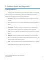
2.1. Design Objectives
In the early stages of the design process, the team decided to identify key objectives that
needed to be met for a successful prototype. After extensive thought, the team was able to
determine the following objectives to be most critical to the project:
•
Performance: Superior wireless communication with special emphasis in packet loss
avoidance
•
Cost: Keeping the price as low as possible without drastically degrading performance or
features
•
Expandability: The ability to add other wireless protocols such as Bluetooth to the
system to target a larger spectrum of devices and improvement in wireless range
•
Power: Low-power components were hand-picked by the team specifically to meet this
objective
•
Robustness: Develop a system that will work continuously in various environments
•
Size: To accommodate typical residential settings, small enough that it is not an eye sore
and large enough to fulfill robustness objective
•
Safety: End-user should not run into any hazards while operating the device, including
proper shielding from the power supply and any electrical wires
Power-over-Ethernet For Wireless Home Automation
Texas Instruments
8
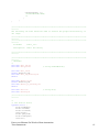
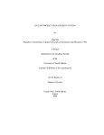
2.2. House of Quality Diagram
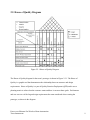
Figure 2.2.1 House of Quality Diagram
The House of Quality diagram for the team’s prototype is shown in Figure 2.2.1. The House of
Quality is a graphic tool that demonstrates the relationship between customer and design
requirements. House of Quality is a part of Quality Function Deployment (QFD) and it uses a
planning matrix to relate what the customer wants and how it can meet those goals. Performance
and cost were two of the largest design requirements the team considered when creating the
prototype, as shown in the diagram.
Power-over-Ethernet For Wireless Home Automation
Texas Instruments
9
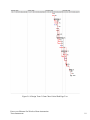
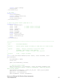
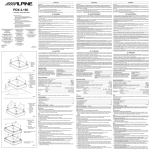
2.3. FAST Diagram
Figure 2.3.1 FAST Diagram: Design Team 3
Our teams FAST (Function Analysis System Technique) diagram can be seen in Figure
2.3.1 above. The purpose of the diagram is to prioritize the objectives or functions of the
product. The diagrams logic is read left to right, with the leftmost object being the basic function
and the rest being secondary. There are three main secondary functions involved in the
completion of the design task: managing all data from the microcontroller; polling the sensors so
that status information and communication can be performed; and finally implementing Power
over Ethernet to power our devices. As the reader moves further right in the diagram, the reason
as to how and why these functions are being performed will become clearer.
Power-over-Ethernet For Wireless Home Automation
Texas Instruments
10
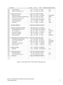
2.4. Feasibility Matrix
Design Criteria
Weight
Power over
Ethernet
Radio
Web Server
Communication
Performance
5
4
5
5
Cost
5
5
5
4
Expandability
4
2
5
4
Power
4
5
5
3
Robustness
3
4
4
2
Size
3
3
4
1
Total
94
114
Table 2.4.1 Feasibility Matrix for Prototype
82
Texas Instruments had addressed that in designing the project, a few constraints should
be met. These included but are not limited to time, cost, performance, power, expandability,
size, and robustness as shown in Table 2.4.1. To deal with time constraint, the team created a
schedule of deadlines in which certain aspects of the project had to be completed. This allowed
the team to satisfy all desired requirements by design day and allowed buffer time to
accommodate for unexpected failures throughout the design process. Along with time comes
cost. Cost was a chief concern for designing this prototype due to the $500 budget constraint per
team. However, many of the parts for our project were distributed directly from Texas
Instruments or its subsidiary Luminary Micro at no cost. (see Table 5.2.1.1). Nonetheless, the
team wanted to keep production cost down so that the design can be realizable in the market.
Performance is by far the most vital design criteria that the team wanted to exceed. Chief
performance concerns include range and efficiency of the wireless signal and inter-protocol
bridging efficiency. Without an efficient wireless and wired signal, both communication
Power-over-Ethernet For Wireless Home Automation
Texas Instruments
11
between web server to circuit and sensor to circuit would be poor or non-existent and the final
design will be useless.
Power consumption was also critical to the teams design. All of the parts utilized in the
design work under the Power over Ethernet IEEE 802.3af hardware power rating standard. The
TPS2384 consumes roughly 480mW in powered mode when all four ports are used and 432mW
in standby with all ports off. The TPS2375 consumers a bit more power roughly in the range of
1-2W due to its requirement to generate ≈15.4W on the CAT5 cable.
Size and robustness are fairly obvious constraints as the team wanted the design to both
be stable and compact. The team’s final design includes a 10” x 14” enclosure that contains all
of the hardware.
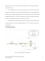
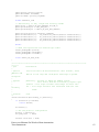
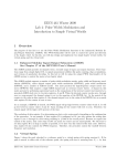
2.5. Design Solution
Figure 2.5.1 Block Diagram for Prototype
Power-over-Ethernet For Wireless Home Automation
Texas Instruments
12
The teams design solution is centered on four main components provided by Texas Instruments.
The first component is the TPS2384, which is the Power Sourcing Equipment (PSE) chip. This
module is critical to the team’s design as it takes a 48V input supply and injects the voltage and
roughly 15.4W of power over the CAT5 Ethernet cable. Since there are four unused wires on
every Ethernet cable, the voltage will be applied to those lines rather than the four wires used for
data transmission. The PSE along with the Power over Ethernet Power Device (PoE PD) must
be in constant interaction with each other to be fully operational. The PSE will continuously
probe and detect if a PoE PD is present. In this detection phase of the PD, 2.7-10.1V is applied
to the power interface to determine whether it can accept the power using incremental resistance
of 25 kΩ signals. If not, the PSE will terminate supplying voltage. The PSE will also shutdown
power to the Ethernet cable if the PD ever becomes disconnected from the network. The PD has
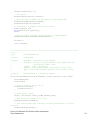
an additional three stages of operation that is determined by the voltage received from the power
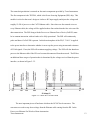
interface, as shown in Figure 2.5.2.
Figure 2.5.2 IEEE 802.3af PD Limits
The next important pieces of hardware which are the DC-DC buck converters. The
converters are used to step down voltage from the Ethernet cable coming from the PD. In the
Power-over-Ethernet For Wireless Home Automation
Texas Instruments
13
team’s design, only one converter is required as both the microcontroller and wireless
transceivers supply voltages can be satisfied with 3.1V.
The wireless system on chip (SoC) consists of the CC2430/F128 module shown in Figure
2.5.3. The module broadcasts a wireless ZigBee signal to interact with any sensors in the
network. The SoC also will constantly interact with the microcontroller through UART
transmissions so that any data collected from the sensors can be logged and managed internally
by the microcontroller. This data can subsequently be accessed through the team’s web server
hosted on the microcontroller, allowing an easy way to manage the system and check on the
status of the sensors locally or remotely.
Figure 2.5.3 CC2430/F128 Wireless SoC Transceivers
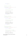
Finally, one of the most vital pieces of hardware to our design, the LM3S8962 microcontroller, is
produced by TI’s subsidiary Luminary Micro. This is the heart of the team’s design and will do
most of the processing and data management. As mentioned above, it will also be in constant
communication with the wireless SoC sending data one byte at a time through UART. Due to
Power-over-Ethernet For Wireless Home Automation
Texas Instruments
14
the processing tasks the microcontroller has in the design, it was programmed intensively for
both UART communication and the hosted web server. In order for the web server to be
accessed, the microcontroller required additional coding to allow for Ethernet connections. This
includes Dynamic Host Configuration Protocol (DHCP) to assign an IP address, and lightweight
TCP/IP stack (lwIP) to control various peripherals on the board via a web browser.
Power-over-Ethernet For Wireless Home Automation
Texas Instruments
15
2.6. Gantt Chart
Figure 2.6.1 Design Team 3 Gantt Chart Tasks Page One
Power-over-Ethernet For Wireless Home Automation
Texas Instruments
16
Figure 2.6.2 Design Team 3 Gantt Chart Tasks Page Two
Power-over-Ethernet For Wireless Home Automation
Texas Instruments
17
Figure 2.6.3 Design Team 3 Gantt Chart Critical Path Page One
Power-over-Ethernet For Wireless Home Automation
Texas Instruments
18
Figure 2.6.4 Design Team 3 Gantt Chart Critical Path Page Two
Power-over-Ethernet For Wireless Home Automation
Texas Instruments
19
Figures 2.6.1 – 2.6.4 are images of Design Team 3’s Gantt chart. The Gantt chart was created
using Microsoft Project 2003. It was a useful tool for monitoring the team’s progress on the
project throughout the semester. It illustrates start and finish dates of important aspects of the
project, including identifying elements that are dependent on other tasks being completed first.
The Gantt chart was updated throughout the semester to accurately determine team progress and
identify problem areas or time concerns.
2.7. Proposed Budget
Quantity
2
2
2
2
1
1
Item
Cost
PSE Module
Provided by Sponsor
PoE PD Module
Provided by Sponsor
ZigBee Radio Transceivers
Provided by Sponsor
LM-3S-8962 microcontroller
Provided by Sponsor
48V Power Supply
$53.12
Wireless Sensors
$138.00
Resistors, Capacitors, Diodes
Provided by MSU
Total Cost
$192.12
Table 2.7.1 Expected Budget for Design Team 3
Shown in Table 2.7.1 is the team’s initial budget estimates halfway through the semester.
Several components needed for the team’s design were provided by project sponsor Texas
Instruments. Many other components including electrical components such as resistors,
capacitors, and diodes were assumed to be in stock at the MSU ECE Shop free of charge
therefore not affecting the team’s $500 budget.
Power-over-Ethernet For Wireless Home Automation
Texas Instruments
20
3. Technical Description
3.1. Hardware Design
In creating our prototype, our hardware design was broken down into three main components:
power sourcing, Power over Ethernet (PoE), and wireless sensors. The following sections will
discuss in more detail their purpose to the team’s prototype and how they were implemented in
the final design.
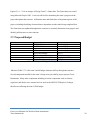
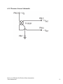
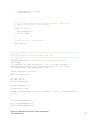
3.1.1. Power Sourcing
The power sourcing component is composed of a 48VDC/0.5A linear power supply and the
TPS2384 Power Sourcing Equipment (PSE) module. The connections between these two
components are shown in Figure 3.1.1.1. The power supply requires 100/120/220/230/240 VAC
which can be supplied from any standard wall outlet. Since no AC adapter comes with the
power supply, simply cutting one end of a standard computer power cable off and stripping the
opposite end to expose the hot, neutral, and ground connections will work well. Before using
this supply, soldering the appropriate jumper connections at the AC input is required. To make
the connections between the power supply and the PSE, wires with higher voltage ratings were
used to accommodate for the 48VDC. Using these wires, connection between the supplies
positive and negative output should then be connected to the Vdd (power) and ground input on the
PSE’s supply block.
Power-over-Ethernet For Wireless Home Automation
Texas Instruments
21
Figure 3.1.1.1 48V Linear Power Supply and TPS2384 PSE
With the appropriate connections made between the supply and the PSE, configuration of
the PSE is necessary to supply the correct voltage on the CAT5 cable. As the TPS2384 is a
quad-port PSE, each port has its own set of jumpers. These jumpers are used to determine which
pins the user wants to apply the 48V on. As mentioned previously, a standard CAT5 cable has
four unused pins. The team decided to apply the voltage on these spare pins, rather than
applying it to the pins that data travels on. By placing the jumper to its corresponding position,
pins four and five will harness the positive voltage while pins seven and eight will contain the
negative voltage. In addition to these jumpers, the TPS2384 has an additional ten jumpers that
must be properly connected in order for correct operation. At this point, the team was able to
successfully read a voltage of approximately 48.1 on the line using a digital multimeter.
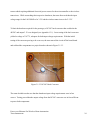
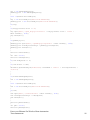
3.1.2. Power-over-Ethernet (PoE)
The next component of the project is the hardware required to implement the PoE. With
the power supply and PSE connected appropriately as discussed in the previous section, the team
was able to add the TPS2375EVM PoE powered device shown in Figure 3.1.2.1.
Power-over-Ethernet For Wireless Home Automation
Texas Instruments
22
Figure 3.1.2.1 Power-over-Ethernet Powered Device TPS2375EVM
The TPS2375 can be configured for various classifications by changing the value of an external
resistor connected between the CLASS and power pins. The team used default class 0, which
allows for 0.44 – 12.95W of power and 0 – 4mA of current. The value of RCLASS was 4.420 kΩ
±1%. All five classes that can be chosen are shown in Table 3.1.2.2.
Class PD Power (W)
RCLASS (Ω)
802.3af Limits (mA)
0
0.44 – 12.95
4420 ± 1%
0–4
1
0.44 – 3.84
953 ± 1%
9 – 12
2
3.84 – 6.49
549 ± 1%
17 – 20
3
6.49 – 12.95
357 ± 1%
26 – 30
4
-
255 ± 1%
36 - 44
Table 3.1.2.2 Classification of TPS2375
The team utilized the TPS2375EVM’s output supply block that allows for the connection of an
external DC-DC converter to step down the 48V to more appropriate voltages. By doing so, the
Power-over-Ethernet For Wireless Home Automation
Texas Instruments
23
team avoided requiring additional electrical power sources for the microcontroller or the wireless
transceivers. While researching their respective datasheets, the team discovered that the input
voltage range for the LM-3S8962 to be 3-5V and the wireless transceivers to be 2-3.2V.
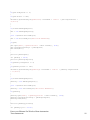
To limit the hardware required for the prototype, a DC-DC buck converter that would take the
48VDC and output 3.1V was designed (see Appendix 6.3.1). Later testing of the buck converter
yielded a voltage of 3.077V, adequate for both input voltage requirements. With the initial
testing of the converter proving to be a success, the team moved the circuit off the bread board
and soldered the components to a project board as shown in Figure 3.1.2.3.
Figure 3.1.2.3 DC-DC Buck Converter
The team decided to make sure that the datasheets input voltage requirements were in fact
correct. Testing proved that the output voltage from the DC-DC converter was in fact sufficient
to power both components.
Power-over-Ethernet For Wireless Home Automation
Texas Instruments
24
3.1.3. Microcontroller
The LM-3S8962 microcontroller forms the core of the team’s design. The microcontroller
essentially mediates between the user interface and the wireless sensors which collect the data as
desired by the user. Below is the pin diagram of the LM-3S8962 according to the datasheet
provided by Luminary Micro. The team was required to become familiar with all pins
throughout the design process in order to determine which pins needed to be connected for
successful communication to and from the CC2430’s.
Figure 3.1.3.1 LM-3S8962 microcontroller Pins
Power-over-Ethernet For Wireless Home Automation
Texas Instruments
25
The LM-3S8962 is a Cortex M3 based-100 pin, 32 bit-computing microcontroller that is cost
effective and aims to deliver 32-bit computing at the cost of 8-bit and 16-bit controllers. Several
reasons went into the decision of selecting LM-3S8962 microcontroller for the design over the
other popular microcontrollers available in the market. Some of the reasons are, small footprint,
extreme power conservation when demanded, Ethernet compatibility, large on-chip memory, a
memory protection unit, flexible timers, ARM’s wide user base-means easy troubleshooting, and
so on. For easier programming and debugging purposes, LM-3S8962 Evaluation Module was
used in the design. The design however was proposed keeping the actual chip in mind. Hence, a
move-over to the actual chip is not seen as a problem. Figure 3.1.3.2 illustrates the block
diagram of the microcontroller.
Figure 3.1.3.2 LM-3S8962 Block Diagram
Power-over-Ethernet For Wireless Home Automation
Texas Instruments
26
As it can be seen from the block diagram, the microcontroller gives the users a lot of options in
terms of serial interfaces. The team decided to use the Universal Asynchronous
Receiver/Transmitter (UART) port for communication between CC2430 and the microcontroller.
This decision was made based upon the availability of UART interface on the WSoC and also
previous UART experience by the team. The Ethernet port was used to access the website.
Hence, this report will further focus on the UART and 10/100 Ethernet interfaces on the
microcontroller. Some of the UART features of the microcontroller include- two programmable
16C550 UARTs with IrDA support, separate lines for FIFO TX and RX, fully programmable
data bits, and so on. The team used the UORX, UOTX, and GND pins on the Evaluation Board
to connect to the WSOC. The memory on the microcontroller was used to host the web server.
Hence, the data received by the microcontroller from the WSoC is processed and organized in
the microcontroller and stored in the 128KB memory. Details on how this data is accessed are
described in the user interface section of this report. The Ethernet port allows the microcontroller
to be connected to a live network and obtain an IP address. This allows the web server to be
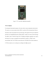
accessible on the web from anywhere in the world. Figure 3.1.3.3 is a picture of the LM-3S8962
Evaluation Module used in the design.
Power-over-Ethernet For Wireless Home Automation
Texas Instruments
27
Figure 3.1.3.3 LM-3S8962 ARM Microcontroller
3.1.4. Sensors
For testing and demonstration purposes, the team used two sensors (temperature and pressure).
The sensors were in-turn connected to the WSOC to perform ADC and transmission of data to
the WSOC on the microcontroller side as per the design. This segment of the report summarizes
the WSOC, the SmartRF04 EB used to flash the WSOC, and the two sensors used in the design.
The WSOC is the CC2430/F-128 chip. The CC2430EMs with ZigBee capabilities were used in
the design. Every sensor is assigned an associated WSOC, and there is a WSOC on the
microcontroller side. The TI Z-Stack comes built in the CC2430EM. This Z-Stack enables the
CC2430 to transmit, receive, and operate according to the ZigBee protocol.
Power-over-Ethernet For Wireless Home Automation
Texas Instruments
28
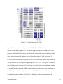
Figure 3.1.4.1 Block Diagram of CC2430
Figure 3.1.4.1 shows the block diagram of the CC2430. The CC2430 is a low power, low cost
wireless solution in the ZigBee (802.15.4) 2.4GHz range. The chip has an enhanced 8051 core
processor with 128 KB flash memory and 8KB RAM. As one of the essential challenges of the
project was to integrate PoE with low power wireless devices, the CC2430 was chosen. The
CC2430 operates at extremely low powers, Rx and Tx at 27mA, and 0.3 micro Amp at stand-by.
The chip operates at a wide range of supply voltage of 2.0 V to 3.6 V. The chip has a total of 48
pins of which three are I/O ports of 8, 8, and 5 pins (21 total I/O pins) and an additional standard
die ground. The chip operates at 32MHz crystal clock, and can also accept other clock inputs on
the XOSC_q2 (pin 43). The chip also possesses two USART lines, and an AES
encryption/decryption capability. The USART on the chip is used to communicate with the
Power-over-Ethernet For Wireless Home Automation
Texas Instruments
29
microcontroller. The details of communication are given in Section 3.2, hardware
implementation.
To program, debug, and flash the CC2430 SmartRF04EB board was used. Figure 3.1.4.2 depicts
the SmartRF04EB, and Figure 2.1.5.2 depicts the CC2430.
Figure 3.1.4.2 SmartRF04 Evaluation Board
The SmartRF04EB is connected to a computer via the USB cable, and is powered at 4.0V. The
working voltage range of the WSOC is 3.0-3.6 V- the board supplies the desired to the WSOC.
The board can also be powered via a battery source (which cannot be seen in the picture as it is
in the bottom of the board). The board also has 40 I/O pins which are directly associated with the
WSOC. Hence, the SmartRF04EB gives an easy solution to program, the board and supply
external inputs simultaneously. Once programmed, the WSOC can work stand alone.
Power-over-Ethernet For Wireless Home Automation
Texas Instruments
30
Figure 3.1.4.3 Temperature Sensor Circuit
Shown in Fig 3.1.4.3 is the project board containing the temperature sensor IC; TMP01FPZ. The
chip is an analog temperature sensor designed by Analog Devices Inc. For the demonstration and
testing purposes, this chip was used to measure the temperature of the room, and display the
result in Fahrenheit (F) degrees. The chip by itself gives voltage proportional in the Kelvin scale
at 5mV/K; the conversion from Kelvin to Fahrenheit was done in the code. The operating voltage
for the sensor is between 4.5 - 13.2V. As the WSoC associated with the sensor only needs 3.3 V,
the batteries were connected in such a way to provide appropriate voltage to both chips. The chip
gives out two output lines, one being the Voltage Proportional to Absolute Temperature
(VPTAT) and the other being a reference line of 2.5V. Hence, the measured temperature is
calculated based on the VPTAT and the reference. The chip also has upper and lower limit
alarms which go high when the temperature sensor measures a temperature higher or lower than
the user set limit. These pins of the chip were left unused in the testing process. This temperature
was implemented successfully and incorporated in the demonstration of the final project.
Power-over-Ethernet For Wireless Home Automation
Texas Instruments
31
Figure 3.1.4.4 MPX200AP Analog Pressure Sensor
The second sensor used for demonstration and testing purposes was the Motorola’s MPX200AP
pressure sensor. The sensor is silicon piezo-resistance based analog measurement of the pressure.
The device outputs a voltage value proportional to the pressure detected. Figure 3.1.4.4 shows
the pressure sensor’s back view. The front view has a pressure side P1. This pressure side P1
measures the pressure applied with respect to the vacuum inside the sensor kept at constant
pressure P2. As the applied pressure deviate more from vacuum pressure P2, the output voltage
deviates from reference offset voltage of 20mV. The sensitivity of the sensor is 0.3mV/kPa, and
the operating voltage is 3.0 V to 6.0 V. The burst pressure of the sensor is 2000 kPa, and the
overpressure (P1>P2) is at 400 kPa. Pin 1 is ground and pin 3 is Vdd, and pin 2 supplies the
positive output voltage and pin 4 supplies negative output voltage. The positive voltage was fed
into the WSoC and was converted to digital value using the ADC on the WSoC. This digital
value was transmitted to the WSoC on the microcontroller side for web server purposes. Thus,
the pressure sensor was successfully implemented.
Power-over-Ethernet For Wireless Home Automation
Texas Instruments
32
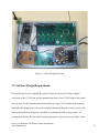
3.2 Hardware Implementation
This section describes the hardware setup and connections of the final prototype that are housed
in a 10” x 14” enclosure. The final prototype can essentially be broken down into three segments.
The prototype has a power supply that is connected to the wall outlet and provides a 48VDC
input to the PSE. Placed next to the power supply is the PSE which injects 48V into the unused
lines of the CAT-5 cable. The other end of the cable is connected to the Powered Device which
outputs 48V from a set of pins, and the data can be collected on the other Ethernet port on the
PD. The output from the PD is then connected to the DC-DC converter which steps down the
voltage to 3.1V as needed by the microcontroller and the WSoC. The website is hosted on the
microcontroller, and the WSoC on the board is connected to the microcontroller through UART
transmission. The sensors, with associated WSoC can be placed anywhere within range so as to
facilitate communication with the WSoC on the board.
On the final product based on the prototype, the power supply and the PSE are put in the backend of the board. This means that the only connection to the board from the external environment
is the CAT-5 cable going to the PSE. Hence, Power over Ethernet for the board is achieved.
Shown in Figure 3.2.1 is the enclosure used to accommodate the main hardware components for
the design.
Power-over-Ethernet For Wireless Home Automation
Texas Instruments
33
Figure 3.2.1 Final Design Enclosure
3.3. Software Design Requirements
ECE 480 Design Team 3 separated the software design into four parts: analog to digital
conversion on the CC2430, the wireless transmission from several CC2430 chips to the central
gateway node, UART communication between the receiving CC2430 and the microcontroller,
and finally the coding for the web server to display information from the wireless sensors. The
project required that the design have the ability to communicate with wireless sensors. To
accommodate for this, the team utilized analog temperature and pressure sensors whose values
Power-over-Ethernet For Wireless Home Automation
Texas Instruments
34
would be converted into digital signals that could be transferred over the CC2430 to the central
node which was also a CC2430 chip programmed to accept several connections. Using the IAR
Embedded Workbench for the 8051 microcontroller, the team was able to utilize both ADC and
RF capabilities by sending/receiving this data using the ZigBee wireless protocol. Distinctions
were made between the several nodes sending data by observing the send and receive address of
each transmitted packet. After the digital signal containing the sensors output values is received,
the team needed to program the receiving CC2430 to communicate with the LM-3S8962
microcontroller through UART. By doing this, the data is stored in FIFO buffers and then
transferred one byte at a time. Subsequently, the microcontroller receives this transmission one
byte at a time and restores it to its original file size. Once the CC2430 was programmed to
transmit through UART, the microcontroller had to be programmed to receive values on the
UART only when the unique signature the CC2430 sends is received. This allows for power
savings and the ability to determine what sensor is transmitting information at any given time.
This is a critical step in creating a wireless sensor network that contains several nodes.
Finally, the microcontroller was programmed further to host a web server for remote
management of any sensors in the network. This was done by creating temporary buffers to
store the received UART communications from the sensors and reading the values in.
For the implementation of the ADC, wirelesses transmission and UART communication,
the coding was done the C language by two different compilers and development environments.
For the CC2430 programming, all code was done with the IAR 7.51 Workbench, with the help of
Hardware Abstraction Layer (HAL) libraries provided by TI. The MCU programming was done
Power-over-Ethernet For Wireless Home Automation
Texas Instruments
35
in a similar environment, the IAR 5.4 Embedded Workbench, with separate libraries for the
StellerisWare 8962 MCU.
3.4. Software Implementation
ECE 480 Design Team 3 was able to create a web server which has the ability to communicate
with any wireless sensors in the network. For the team’s design, this involves the temperature
sensor and pressure sensor. By logging in to the web server, the consumer can easily read the
values of sensors. For instance, using a temperature sensor to continuously monitor the
environment of a temperature-dependant space can be used in several situations such as server
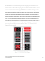
rooms. Shown in Figure 3.4.1 is a screen capture of the web server created by the team running
in Mozilla Firefox.
Figure 3.4.1 ECE 480 Design Team 3’s Web Server
Power-over-Ethernet For Wireless Home Automation
Texas Instruments
36
When the proper network connections are made, the web server can be accessed anywhere an
Internet connection is available. As the server utilizes JavaScript, the web server can also be
accessed on any modern Smartphone including BlackBerry’s and the iPhone. Of course in order
for this web server to handle any useful information, the proper coding documented in Section
3.3 must already be in place. The team was able to do all the necessary coding for a fully
functional web server. By pressing the ‘Get Pressure’ button on the server, a JavaScript
‘onclick’ call is made to the microcontroller. This will send a request to the associated CC2430
to send its current value. After the receiving CC2430 node obtains this value, it will then send to
the microcontroller through UART. This value will then be sent to the appropriate location
depending on which function is called. This same procedure is used for the ‘Get Temperature’
button as well due to its similar operational mode. Depending on which function is called, the
appropriate formulas will be applied to convert a voltage in to either a Fahrenheit temperature or
a Pascal pressure.
Power-over-Ethernet For Wireless Home Automation
Texas Instruments
37
4. Functional Design Testing
4.1. Results
The 48V power supply when connected to the wall outlet gave an output of 48.192 VDC. This
voltage was then transferred to the PSE using 300V rated wires, where jumpers were set to inject
the power on the empty lines of the CAT-5 cable. The PSE comes in three modes of operation:
auto mode, semi-auto mode, and power management mode. The power management mode
combined with a low cost, low power microcontroller like the MSP 430 gives an effective
solution for power management. The power management mode (PMM) has 13 functions which
give various options to the user like, supplying only 4.4V to the PD, supplying only 8.8V to the
PD, a disable function and several others. This project uses the PSE in its auto mode- self
sufficient and intelligent mode. The advantage of power management mode is the access to the
addresses microcontroller via I2C, management of power on the back end of the circuit when
PSE is positioned away from the PD and the microcontroller.
When measured in the laboratory, the PD outputs a voltage of 46.329 V. The amount of
power on the CAT-5 was calculated to be around 12.94W, slightly less than theoretical max of
15.W dictated by the IEEE 802.3af standard as expected. The power was sufficient in testing of
the PoE IP camera the team purchased for demonstration purposes. The TPS2375 used as the
powered device in the design is another intelligent power management circuit which operates in
three modes, namely detection, classification, and operation. The PSE does not supply voltage to
the power unless it detects a PD on the other end. Hence, the PD should respond the detection
Power-over-Ethernet For Wireless Home Automation
Texas Instruments
38
query of the PSE. The PD also have four classification of resistors placed around the TPS2375
which control how much power goes to the Vdd and RTN pins.
Initial testing of the CC2430’s wireless capability yielded an indirect range of 124 feet between
sending and receiving nodes. The two nodes were not in direct sight of each other and heavy
concrete in the Engineering Building can account for this limited range. However, the nodes
were easily able to communicate with each other while on different levels of the building. They
were also able to transfer further than 300 feet while in direct view of each other. The CC2430 is
also a low power wireless solution despite these optimistic results. The chip has two clocks for
basic operation, which can be chosen by the designer for faster speed or lower power
applications. One of these clocks is a 16 MHz RC oscillator, while the other is a 32 MHz crystal
oscillator. The chip can also take an external clock input, which can be useful for less typical
environments.
The chip only consumes 0.5µA of current in sleep mode, and 0.3µA in stand-by-mode with
wake-up time of 50ms. The microcontroller ran with roughly 9.5mA of current and low load, and
never exceeded 12.3 mA in the team’s testing. While transmitting, the CC2430 used ≈26.7mA
of current and 26.9mA when receiving. The radio takes a typical wake-up time of 192ms and
with a Tx/Rx turnaround time of 192ms as well. Hence, the team’s choice of using the
CC4230EM for wireless transmission was a good one. The design specification of low-power
was easily met using the CC2430 in the design.
Power-over-Ethernet For Wireless Home Automation
Texas Instruments
39
5. Conclusions
5.1. Summary
ECE 480 Design Team 3 was given an opportunity to design a multi-faceted system for Texas
Instruments. The first task was to implement Power-over-Ethernet (PoE) in the design. The
team successfully created a prototype in which both PoE enabled devices and non-PoE enabled
devices could be used in the network. This was shown by powering the LM-3S892
microcontroller, the CC2430 wireless transceiver, and the PoE powered device using a CAT-5
powered by the Power Sourcing Equipment (PSE). Utilizing the PoE PD’s external DC-DC
connection block, the team was able to create a DC-DC Buck converter that could provide
voltage internally to devices that are not PoE ready.
The second task was to create a gateway that would allow wireless sensor networks to be
connected into a LAN or the internet for building/home control. The team was able to
demonstrate the potential for this technology by utilizing temperature and pressure sensors.
However, due to limited budget and time constraints, the team was slightly inhibited as to how
many sensor nodes the team could place in the network.
The team was able to meet the main design specifications asked by the sponsor, including
providing a low-power, safe, and effective prototype. The final design communicates wirelessly
between two sensors as expected, while third party devices were tested and confirmed to have
the ability to be powered over Ethernet. The project has great potential that can be worked on
with further funding and time, including adding different wireless protocols and expanding the
Power-over-Ethernet For Wireless Home Automation
Texas Instruments
40
wireless sensor network to accommodate for more nodes. Further discussion on the team’s
thoughts on what could be improved and possible implementations is shown in Section 5.3.
5.2. Final Budget
Item
PSE Module (TPS2384)
PoE PD Module (TPS2375)
ZigBee Transceiver (CC2430)
microcontroller (LM-3S8962)
48V Linear Power Supply
CC2430 Debugger (SmartRF04EB)
DC-DC Regular (LM2594HV)
PoE-Capable IP Security Camera
Digital Temperature IC (DS1621)
3V AA Lithium Battery
Schottky Diode (MBR150)
180 µH Inductor
12000 pF Capacitor
0.22 µF Capacitor
10000 pF Capacitor
Analog Temperature IC (TMP01FP)
Supplier
Quantity
Texas Instruments
2
Texas Instruments
2
Texas Instruments
2
Texas Instruments
2
MSU ECE Shop
1
Texas Instruments
2
MSU ECE Shop
6
MSU ECE Shop
1
MSU ECE Shop
3
MSU ECE Shop
4
MSU ECE Shop
4
MSU ECE Shop
4
MSU ECE Shop
4
MSU ECE Shop
4
MSU ECE Shop
4
MSU ECE Shop
4
Total Cost
Table 5.2.1.Final Budget Design Team 3
Cost/ea.
----$53.12
-$4.28
$108.24
$4.61
$5.00
$0.43
$2.99
$0.36
$0.91
$0.42
$5.76
Total
----$53.12
-$25.68
$108.24
$13.83
$20.00
$1.72
$11.96
$1.44
$3.64
$1.68
$17.28
$258.59
Table 5.2.1 shows all required parts to produce the team’s final prototype. Several key
components were supplied through the projects sponsor Texas Instruments, which allowed the
team to stay under budget. Many parts were bought in larger quantities to account for any
problems with electrostatic discharge or burnout. Throughout the design process, only one part
had to be replaced due to its incompatibility with the final prototype.
5.3 Future Improvements
Power-over-Ethernet For Wireless Home Automation
Texas Instruments
41
Throughout the design process, the team has continuously thought of ways to further improve the
overall prototype but could not due to time, budget, and software constraints. The following are
key features that could be added without these limitations:
•
Bluetooth wireless transmission: The prototype consists of ZigBee transmission
currently, and while ZigBee is a great low-power protocol, it doesn’t have a large
wireless range. Adding Bluetooth accessibility would not only allow for sensors to be
further away from the main board, it would also allow for a greater range of products to
be added to the network.
•
IEEE 802.3at: Power-over-Ethernet Plus: The teams design consists of systems
conforming to the IEEE 802.af standard, which allows for 15.W theoretical max power to
each powered device. The developing IEEE 802.3at standard will allow for 30W per PD,
which could power components such as videophones, dual-band access points, and
several other electronic devices.
•
Expandability: Currently, the prototype only has the ability to interact with two
wireless sensors due to budget and code size limitations with the compiler the team used.
Since each sensor requires two CC2430 modules, more hardware would be required. The
team had hoped to add more nodes to the network, thus expanding the projects
capabilities is one of the largest areas that could be improved on.
6. Appendix
6.1. Technical Roles
Power-over-Ethernet For Wireless Home Automation
Texas Instruments
42
6.1.1. David DeLuca
David DeLuca was responsible for designing the power sourcing hardware
and assisting in coding of the microcontroller. This included working
extensively with the power supply and the power sourcing equpiment.
Tasks included wiring, soldering, configuration of jumpers, and testing to
see if the PSE was delivering the expected 48V on the CAT5 cable. After David verified that the
CAT5 cable had 48V on the line using a digital multimeter, he then wired all necessary
connections from the PSE to the PoE PD. Verifying that the PoE PD was succesfully being
powered over Ethernet, David then set out to design the DC-DC buck converters required to step
down the voltage from 48V to roughly 3.1V. David realized that 3.1V would be a sufficient
supply voltage for both the LM-3S8962 and the CC2430. After calculating and determing all the
parts needed to achieve the design, David and Hassan built the converters and tested the output
via a digital multimeter. David also built the temperature sensor circuit powered by a series
connection of two-AA batteries and soldered all components to a project board.
David also worked with Sasang to program the LM-3S8962 to receive data from the CC2430
using UART. The data sent and received in the UART was sent from the CC2430’s analog to
digital converter, as both the pressure sensor and temperature sensor have analog outputs.
Without this communication between the two devices, the web server aspect of the project could
not be realized. All coding was done using IAR Embedded Workbench compiler for the ARM
microcontroller.
Power-over-Ethernet For Wireless Home Automation
Texas Instruments
43
David was also responsible for the setup of the PoE camera and all networking aspects involved.
David tested two different networking scenarios to view the camera remotely. The first was
using a traditional router with DHCP, in which three Ethernet patch cables were required.
However, David decided to try a new scenario in which the extra hardware the router creates
could be removed by using two crossover CAT5 cables instead. Static IP addresses on the
computer network card and the IP camera were necessary for the two devices to communicate
with each other using this method. Both systems worked as planned and the team collectively
decided to use the second method on design day to demonstrate functionality.
6.1.2. Sasang Balachandran
Sasang’s main responsibilities were with the software development for the
project. From the programming and integration of the outer sensor nodes to
the coding and initialization of the central gateway node, the communication
with all components within the entire network was completed by Sasang. His
first focus was on the outer sensor nodes, the connection of the analog
pressure and temperature sensors to the wireless CC2430 device was done through the ADC
interface. The chips had to be programmed though the Hardware Abstraction Layer (HAL)
libraries provided by TI. All embedded programming was done in the C language.
The secondary focus was on the communication between other transmitting wireless
nodes and the central receiving gateway node. The functions and operations needed for RF
transmit and receive were done though the help of the HAL libraries. Sasangs next focus was on
the communication between the central receiving node and the LM3S8962 MCU. The data
Power-over-Ethernet For Wireless Home Automation
Texas Instruments
44
transfer was done through the use of UART protocols, where the two different IAR compilers
were used to programming each chip and incorporate efficient UART communication between
the wireless receiver and the MCU.
Sasangs final focus was on the transfer of data to and from the MCU to the embedded
web server, Sasang programmed the MCU to parse and handle messages left by a JavaScript
enabled website, he also developed the main website with JavaScript to display sensor data in a
user friendly environment.
6.1.3. Hassan Abdullahi
Since Hassan is the only electrical engineering student in the group, he was
responsible for all the electrical hardware components in the system
including but not limited to designing circuits for the pressure and
temperature sensors, DC-DC converters. Almost, of the PCB design and
implementation was completed by Hassan. Much of Hassan’s work was to
design and implement circuits that will work with the DC-DC converter LM2594HV chip so we
can step down the 48VDC from the power supply to use for the wireless SoC and for the
pressure and temperature sensors.
Hassan has made a significant contribution to achieving the team’s goal and objective; therefore,
he was heavily involved in the development and testing stages. He worked with the other team
members to fully integrate all the sub-systems that he had helped develop into one whole system
that perform product requirements. Throughout, the project design process, Hassan was involved
with getting answers and outside help for technical questions that the team could not come up
Power-over-Ethernet For Wireless Home Automation
Texas Instruments
45
answers with. Hassan made outside calls to Xbee, Digi-Key and TrendNet to get technical
understanding of their product so the team could fully utilize and integrate their products to our
design.
On all the different aspects of the project that Hassan has helped, he has tremendously identified
and learned new design issues, constraints and implemented strategic and agreeable solutions in
which he has shared with all the team members. His excessive involvement of the team project
has helped him to fully integrate his learning and hands-on experience in his future endeavor.
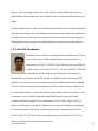
6.1.4. Karthik Hemmanur
Karthik’s focus was relatively on integration and troubleshooting of various
aspects of the project. Karthik identified the operating conditions and
characteristics of TPS 2375 and TPS 2384. Karthik was also responsible for
isolating the pins to be used on TPS 2375, TPS 2384, and WSOC CC2430 as
needed for the project. Karthik successfully integrated the PSE-PD part of the design and
obtained Power over Ethernet on the PD. Karthik was responsible for the identification and
installation of essential software for programming the microcontroller and the WSOC. Karthik
was also involved in identifying the components on WSOC and their working constraints. For
the final design, Karthik was responsible for powering the WSOC stand alone, and also be able
to transmit/ receive the WSOC without the SmartRF04EB board. For the same, Karthik
contacted the technical support of Texas Instruments, as well as an RF engineer with TI to
identify the connections on the WSOC. Karthik was also involved in taking the measurements
for results and analysis of the project. Karthik obtained power consumption values for the
CC2430, TPS 2375, TPS 2384, and also isolated the modes of operation for TPS 2385/2375.
Power-over-Ethernet For Wireless Home Automation
Texas Instruments
46
Karthik obtained values from the WSOC datasheet such as wake-up time, current consumption in
low power ranges and so on. These values are of great significance to the project, as the primary
focus of the design was to obtain a low power system. Karthik also assisted in the DC-DC
converter issues the team faced.
Power-over-Ethernet For Wireless Home Automation
Texas Instruments
47
6.2. References
[1] StellarisWare, Firmware Development Package. [Online]. Austin, TX. Luminary Micro,
2009.
[2] “BLIP Tutorial,” rev. Sep. 19, 2009. [Online]. Available:
http://smote.cs.berkeley.edu:8000/tracenv/wiki/blip. [Accessed: Sep. 20, 2009].
[3] "The lwIP TCP/IP Stack." May 05, 2004. [Online]. Available:
http://www.sics.se/~adam/lwip/. [Accessed: Sep. 02, 2009].
[4] Luminary Micro Technical Staff, LM3S8962 Evaluation Board, User's Manual, Texas
Instruments, 2009. Available
at: http://www.luminarymicro.com/index.php?option=com_remository&func=download&id=52
3&chk=222579d07d3e13fde74ae411749ae30e&Itemid=591
[5] TPS2375 Power-over-Ethernet Powered Device
http://focus.ti.com/lit/ug/slvu126c/slvu126c.pdf
[6] TPS2384 Power Sourcing Equipment
http://focus.ti.com/lit/ds/symlink/tps2384.pdf
[7] LM2954HV Step Down Voltage Regulator
http://cache.national.com/ds/LM/LM2594HV.pdf
[8] DS1621 Digital Thermometer
http://datasheets.maxim-ic.com/en/ds/DS1621.pdf
[9] TMP01FPZ Low Power Programmable Temperature Controller
http://www.analog.com/static/imported-files/data_sheets/TMP01.pdf
[10] CC2430 Wireless System on Chip
http://focus.ti.com/lit/ds/symlink/cc2430.pdf
[11] MBR150 Schottky Diode
http://www.onsemi.com/pub_link/Collateral/MBR150-D.PDF
[12] HB48-0.5-AG 48V 0.5A Linear Power Supply
http://www.power-one.com/resources/products/datasheet/lin.pdf
[13] TV-IP501P PoE IP Camera
http://downloads.trendnet.com/tv-ip501p/datasheet/en_spec_tv-ip501p(v1.0r)-091009.pdf
[14] MPX200AP Uncompensated Silicon Pressure Sensor
http://www.datasheetcatalog.org/datasheet/motorola/MPX200GVSX.pdf
Power-over-Ethernet For Wireless Home Automation
Texas Instruments
48
6.3. Technical Attachments
6.3.1. DC-DC Buck Converter Schematic
Power-over-Ethernet For Wireless Home Automation
Texas Instruments
49
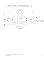
6.3.2 TPS2375 (PoE PD) and TPS2384 (PSE) Schematic
Power-over-Ethernet For Wireless Home Automation
Texas Instruments
50
6.3.3 Pressure Sensor Schematic
Power-over-Ethernet For Wireless Home Automation
Texas Instruments
51
6.3.4. Temperature Sensor Schematic
Power-over-Ethernet For Wireless Home Automation
Texas Instruments
52
6.4 C Source Code
/****************************************************************************
*******
This code is used to take analog input from the sensors, convert to digital
values,
then format the data to bytes for wireless transmission. The data is
transmitted
from the CC2430 to a specific address that is the central node with a
receiving CC2430.
*****************************************************************************
******/
#include
#include
#include
#include
#include
#include
#include
#include
#include
#include
#include
#include
<hal_lcd.h>
<hal_led.h>
<hal_joystick.h>
<hal_assert.h>
<hal_board.h>
<hal_adc.h>
<hal_int.h>
"hal_mcu.h"
"hal_button.h"
"hal_rf.h"
"util_lcd.h"
"basic_rf.h"
/****************************************************************************
*******
* CONSTANTS
*/
// Application parameters
#define RF_CHANNEL
25
// 2.4 GHz RF channel
// BasicRF address definitions
#define PAN_ID
0x2007
#define APP_PAYLOAD_LENGTH
1
#define LIGHT_TOGGLE_CMD
0
// Application states
#define IDLE
#define SEND_CMD
0
1
// Application role
#define NONE
#define SWITCH
#define LIGHT
#define APP_MODES
0
1
2
2
static basicRfCfg_t basicRfConfig;
Power-over-Ethernet For Wireless Home Automation
Texas Instruments
53
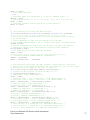
void main(void)
{
basicRfConfig.panId = 0x2007;
basicRfConfig.channel = 25;
basicRfConfig.ackRequest = TRUE;
// Initalise board peripherals
halBoardInit();
halJoystickInit();
// Initalise hal_rf
if(halRfInit()==FAILED) {
HAL_ASSERT(FALSE);
}
// Indicate that device is powered
halLedSet(1);
// Initialize BasicRF
basicRfConfig.myAddr = 0x3330;
if(basicRfInit(&basicRfConfig)==FAILED) {
HAL_ASSERT(FALSE);
}
// Keep Receiver off when not needed to save power
basicRfReceiveOn();
// Main loop
int tmp = 111;
int16 r;
int8 a,b,c;
halLcdWriteLine(HAL_LCD_LINE_1, "Receiving...");
while (TRUE) {
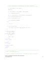
while(!basicRfPacketIsReady());
char *pRxData;
if(basicRfReceive(pRxData, 3, NULL)>0) {
a = pRxData[0];
b = pRxData[1];
c = pRxData[2];
tmp = (int)((int)(a*1000) + (int)(b*100) + (int)(c));
utilLcdDisplayValue(HAL_LCD_LINE_2, "Val: ", tmp,"");
}
}
}
/****************************************************************************
*******
This code receives the digital transmission of the ADC conversion and
wireless transmission
from the sending sensor nodes. After receiving the data, the CC2430 will
send
the formatted values over to the LM3S8962 MCU over UART portocols with a
particualar
signature that indicates which sensor te data is from
Power-over-Ethernet For Wireless Home Automation
Texas Instruments
54
*****************************************************************************
******/
/****************************************************************************
*******
* INCLUDES
*/
#include <hal_lcd.h>
#include <hal_led.h>
#include <hal_joystick.h>
#include <hal_assert.h>
#include <hal_board.h>
#include <hal_adc.h>
#include <hal_int.h>
#include "hal_mcu.h"
#include "hal_button.h"
#include "hal_rf.h"
#include "util_lcd.h"
#include "basic_rf.h"
/****************************************************************************
*******
* CONSTANTS
*/
// Application parameters
#define RF_CHANNEL
25
// 2.4 GHz RF channel
// BasicRF address definitions
#define PAN_ID
0x2007
#define APP_PAYLOAD_LENGTH
1
#define LIGHT_TOGGLE_CMD
0
// Application states
#define IDLE
#define SEND_CMD
0
1
// Application role
#define NONE
#define SWITCH
#define LIGHT
#define APP_MODES
0
1
2
2
/****************************************************************************
*******
* LOCAL VARIABLES
*/
static basicRfCfg_t basicRfConfig;
// Define and allocate a setup structure for the UART protocol:
typedef struct {
unsigned char uartNum : 1; // UART peripheral number (0 or 1)
unsigned char START : 1; // Start bit level (low/high)
unsigned char STOP : 1; // Stop bit level (low/high)
unsigned char SPB : 1; // Stop bits (0 => 1, 1 => 2)
unsigned char PARITY : 1; // Parity control (enable/disable)
unsigned char BIT9 : 1; // 9 bit enable (8bit / 9bit)
Power-over-Ethernet For Wireless Home Automation
Texas Instruments
55
unsigned char D9 : 1; // 9th bit level or Parity type
unsigned char FLOW : 1; // HW Flow Control (enable/disable)
unsigned char ORDER : 1; // Data bit order(LSB/MSB first)
} UART_PROT_CONFIG;
UART_PROT_CONFIG __xdata uartProtConfig;
// Define size of allocated UART RX/TX buffer (just an example)
#define SIZE_OF_UART_RX_BUFFER 50
#define SIZE_OF_UART_TX_BUFFER SIZE_OF_UART_RX_BUFFER
// Allocate buffer+index for UART RX/TX
unsigned short __xdata uartRxBuffer[SIZE_OF_UART_RX_BUFFER];
unsigned short __xdata uartTxBuffer[SIZE_OF_UART_TX_BUFFER];
unsigned short __xdata uartRxIndex, uartTxIndex;
void
void
void
void
void
void
void
uartMapPort(unsigned char uartPortAlt, unsigned char uartNum);
uartInitBitrate(unsigned char uartBaudM, unsigned char uartBaudE);
uartInitProtocol(UART_PROT_CONFIG* uartProtConfig);
uart0Send(unsigned short* uartTxBuf, unsigned short uartTxBufLength);
uart1Send(unsigned short* uartTxBuf, unsigned short uartTxBufLength);
uart0Receive(unsigned short* uartRxBuf, unsigned short uartRxBufLength);
uart1Receive(unsigned short* uartRxBuf, unsigned short uartRxBufLength);
// C language code:
// This function maps/connects the UART to the desired SoC I/O port.
// The application should call this function with "uartPortAlt" = 1 or 2,
// and "uartNum" = 0 or 1.
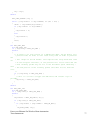
void uartMapPort(unsigned char uartPortAlt, unsigned char uartNum) {
// If UART Port Alternative 1 desired
if(uartPortAlt == 1) {
// If UART0 desired
if (uartNum == 0) {
// Configure UART0 for Alternative 1 => Port P0 (PERCFG.U0CFG = 0)
PERCFG &= ~0x01;
// Configure relevant Port P0 pins for peripheral function:
// P0SEL.SELP0_2/3/4/5 = 1 => RX = P0_2, TX = P0_3, CT = P0_4, RT = P0_5
P0SEL |= 0x3C;
// Configure relevant Port P1 pins back to GPIO function
P1SEL &= ~0x3C;
// Else (UART1 desired)
} else {
// Configure UART1 for Alternative 1 => Port P0 (PERCFG.U1CFG = 0)
PERCFG &= ~0x02;
// Configure relevant Port P0 pins for peripheral function:
// P0SEL.SELP0_2/3/4/5 = 1 => CT = P0_2, RT = P0_3, TX = P0_4, RX = P0_5
P0SEL |= 0x3C;
// Configure relevant Port P1 pins back to GPIO function
P1SEL &= ~0xF0;
}
// Else (UART Port Alternative 2 desired)
} else {
// If UART0 desired
if (uartNum == 0) {
// Configure UART0 for Alternative 2 => Port P1 (PERCFG.U0CFG = 1)
PERCFG |= 0x01;
// P1SEL.SELP1_2/3/4/5 = 1 => CT = P1_2, RT = P1_3, RX = P1_4, TX = P1_5
P1SEL |= 0x3C;
// Configure relevant Port P0 pins back to GPIO function
Power-over-Ethernet For Wireless Home Automation
Texas Instruments
56
P0SEL &= ~0x3C;
// Else (UART1 desired)
} else {
// Configure UART1 for Alternative 2 => Port P1 (PERCFG.U1CFG = 1)
PERCFG |= 0x02;
// P1SEL.SELP1_4/5/6/7 = 1 => CT = P1_4, RT = P1_5, TX = P1_6, RX = P1_7
P1SEL |= 0xF0;
// Configure relevant Port P0 pins back to GPIO function
P0SEL &= ~0x3C;
}
}
}
// This function initializes the UART bit rate.
void uartInitBitrate(unsigned char uartBaudM, unsigned char uartBaudE) {
///////////////////////////////////////////////////////////////
// This initial code section ensures that the SoC system clock is driven
// by the HS XOSC:
// Clear CLKCON.OSC to make the SoC operate on the HS XOSC.
// Set CLKCON.TICKSPD/CLKSPD = 000 => system clock speed = HS RCOSC speed.
CLKCON &= 0x80;
// Monitor CLKCON.OSC to ensure that the HS XOSC is stable and actually
// applied as system clock source before continuing code execution
while(CLKCON & 0x40);
// Set SLEEP.OSC_PD to power down the HS RCOSC.
SLEEP |= 0x04;
///////////////////////////////////////////////////////////////
// Initialize bitrate (U0BAUD.BAUD_M, U0GCR.BAUD_E)
U0BAUD = uartBaudM;
U0GCR = (U0GCR&~0x1F) | uartBaudE;
}
// This function initializes the UART protocol (start/stop bit, data bits,
// parity, etc.). The application must call this function with an initialized
// data structure according to the code in Figure 12.
void uartInitProtocol(UART_PROT_CONFIG* uartProtConfig) {
// Initialize UART protocol for desired UART (0 or 1)
if (uartProtConfig->uartNum == 0) {
// USART mode = UART (U0CSR.MODE = 1)
U0CSR |= 0x80;
// Start bit level = low => Idle level = high (U0UCR.START = 0)
// Start bit level = high => Idle level = low (U0UCR.START = 1)
U0UCR = (U0UCR&~0x01) | uartProtConfig->START;
// Stop bit level = high (U0UCR.STOP = 1)
// Stop bit level = low (U0UCR.STOP = 0)
U0UCR = (U0UCR&~0x02) | (uartProtConfig->STOP << 1);
// Number of stop bits = 1 (U0UCR.SPB = 0)
// Number of stop bits = 2 (U0UCR.SPB = 1)
U0UCR = (U0UCR&~0x04) | (uartProtConfig->SPB << 2);
// Parity = disabled (U0UCR.PARITY = 0)
// Parity = enabled (U0UCR.PARITY = 1)
U0UCR = (U0UCR&~0x08) | (uartProtConfig->PARITY << 3);
// 9-bit data disable = 8 bits transfer (U0UCR.BIT9 = 0)
// 9-bit data enable = 9 bits transfer (U0UCR.BIT9 = 1)
U0UCR = (U0UCR&~0x10) | (uartProtConfig->BIT9 << 4);
// Level of bit 9 = 0 (U0UCR.D9 = 0), used when U0UCR.BIT9 = 1
// Level of bit 9 = 1 (U0UCR.D9 = 1), used when U0UCR.BIT9 = 1
// Parity = Even (U0UCR.D9 = 0), used when U0UCR.PARITY = 1
Power-over-Ethernet For Wireless Home Automation
Texas Instruments
57
// Parity = Odd (U0UCR.D9 = 1), used when U0UCR.PARITY = 1
U0UCR = (U0UCR&~0x20) | (uartProtConfig->D9 << 5);
// Flow control = disabled (U0UCR.FLOW = 0)
// Flow control = enabled (U0UCR.FLOW = 1)
U0UCR = (U0UCR&~0x40) | (uartProtConfig->FLOW << 6);
// Bit order = MSB first (U0GCR.ORDER = 1)
// Bit order = LSB first (U0GCR.ORDER = 0) => For PC/Hyperterminal
U0GCR = (U0GCR&~0x20) | (uartProtConfig->ORDER << 5);
} else {
// USART mode = UART (U1CSR.MODE = 1)
U1CSR |= 0x80;
// Start bit level = low => Idle level = high (U1UCR.START = 0)
// Start bit level = high => Idle level = low (U1UCR.START = 1)
U1UCR = (U1UCR&~0x01) | uartProtConfig->START;
// Stop bit level = high (U1UCR.STOP = 1)
// Stop bit level = low (U1UCR.STOP = 0)
U1UCR = (U1UCR&~0x02) | (uartProtConfig->STOP << 1);
// Number of stop bits = 1 (U1UCR.SPB = 0)
// Number of stop bits = 2 (U1UCR.SPB = 1)
U1UCR = (U1UCR&~0x04) | (uartProtConfig->SPB << 2);
// Parity = disabled (U1UCR.PARITY = 0)
// Parity = enabled (U1UCR.PARITY = 1)
U1UCR = (U1UCR&~0x08) | (uartProtConfig->PARITY << 3);
// 9-bit data enable = 8 bits transfer (U1UCR.BIT9 = 0)
// 9-bit data enable = 8 bits transfer (U1UCR.BIT9 = 1)
U1UCR = (U1UCR&~0x10) | (uartProtConfig->BIT9 << 4);
// Level of bit 9 = 0 (U1UCR.D9 = 0), used when U1UCR.BIT9 = 1
// Level of bit 9 = 1 (U1UCR.D9 = 1), used when U1UCR.BIT9 = 1
// Parity = Even (U1UCR.D9 = 0), used when U1UCR.PARITY = 1
// Parity = Odd (U1UCR.D9 = 1), used when U1UCR.PARITY = 1
U1UCR = (U1UCR&~0x20) | (uartProtConfig->D9 << 5);
// Flow control = disabled (U1UCR.FLOW = 0)
// Flow control = enabled (U1UCR.FLOW = 1)
U1UCR = (U1UCR&~0x40) | (uartProtConfig->FLOW << 6);
// Bit order = MSB first (U1GCR.ORDER = 1)
// Bit order = LSB first (U1GCR.ORDER = 0) => For PC/Hyperterminal
U1GCR = (U1GCR&~0x20) | (uartProtConfig->ORDER << 5);
}
}
// The two functions below send a range of bytes on the UARTx TX line. Note
// that, before the relevant function is called the application must execute
// the initialization code in Figure 3, Figure 11, Figure 12, and Figure 13.
// The code implements the following steps:
// 1. Clear TX interrupt request (UTXxIF = 0).
// 2. Loop: send each UARTx source byte on the UARTx TX line.
// 2a. Read byte from the allocated UART TX source buffer and write to
UxDBUF.
// 2b. Wait until UART byte has been sent (UTXxIF = 1).
// 2c. Clear UTXxIF.
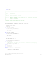
void uart0Send(unsigned short* uartTxBuf, unsigned short uartTxBufLength) {
unsigned short uartTxIndex;
UTX0IF = 0;
for (uartTxIndex = 0; uartTxIndex < uartTxBufLength; uartTxIndex++) {
U0DBUF = uartTxBuf[uartTxIndex];
while( !UTX0IF );
UTX0IF = 0;
Power-over-Ethernet For Wireless Home Automation
Texas Instruments
58
}
}
void uart1Send(unsigned short* uartTxBuf, unsigned short uartTxBufLength) {
unsigned short uartTxIndex;
UTX1IF = 0;
for (uartTxIndex = 0; uartTxIndex < uartTxBufLength; uartTxIndex++) {
U1DBUF = uartTxBuf[uartTxIndex];
while( !UTX1IF );
UTX1IF = 0;
}
}
// The two functions below receive a range of bytes on the UARTx RX line.
// Note that, before this function is called the application must execute
// the UART initialization code in Figure 3, Figure 11, Figure 12, and
// Figure 13.
// The code implements the following steps:
// 1. Enable UARTx RX (UxCSR.RE = 1)
// 2. Clear RX interrupt request (set URXxIF = 0)
// 3. Loop: receive each UARTx sample from the UARTx RX line.
// 3a. Wait until data received (URXxIF = 1).
// 3b. Read UxDBUF and store the value in the allocated UART RX target
buffer.
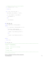
void uart0Receive(unsigned short* uartRxBuf, unsigned short uartRxBufLength)
{
unsigned short uartRxIndex;
U0CSR |= 0x40; URX0IF = 0;
for (uartRxIndex = 0; uartRxIndex < uartRxBufLength; uartRxIndex++) {
while( !URX0IF );
uartRxBuf[uartRxIndex] = U0DBUF;
URX0IF = 0;
}
}
void uart1Receive(unsigned short* uartRxBuf, unsigned short uartRxBufLength)
{
unsigned short uartRxIndex;
U1CSR |= 0x40; URX1IF = 0;
for (uartRxIndex = 0; uartRxIndex < uartRxBufLength; uartRxIndex++) {
while( !URX1IF );
uartRxBuf[uartRxIndex] = U1DBUF;
URX1IF = 0;
}
}
void main(void)
{
basicRfConfig.panId = 0x2007;
basicRfConfig.channel = 25;
basicRfConfig.ackRequest = TRUE;
// Initalise board peripherals
halBoardInit();
halJoystickInit();
// Initalise hal_rf
if(halRfInit()==FAILED) {
HAL_ASSERT(FALSE);
Power-over-Ethernet For Wireless Home Automation
Texas Instruments
59
}
// Indicate that device is powered
halLedSet(1);
// Initialize BasicRF
basicRfConfig.myAddr = 0x3330;
if(basicRfInit(&basicRfConfig)==FAILED) {
HAL_ASSERT(FALSE);
}
// Keep Receiver off when not needed to save power
basicRfReceiveOn();
// Main loop
//UART initialization-----Added new
uartProtConfig.uartNum=0x00;
uartProtConfig.START=0x00;
uartProtConfig.STOP=0x01;
uartProtConfig.SPB=0x00;
uartProtConfig.PARITY=0x00;//PARITY DISABLED
uartProtConfig.BIT9=0x00;
uartProtConfig.D9=0x01;//as that of STOP bit
uartProtConfig.FLOW=0x01;//flow control enabled
uartProtConfig.ORDER=0x00;//LSB first
uartMapPort(1,0); //Mapping UART to SoC i/o
uartInitBitrate(216,11); //Initializing the UART Baud Rate Generator---115,200 BPS
uartInitProtocol(&uartProtConfig); //Initializing the UART Protocol
short tmp = 0;
int16 r;
int8 a,b,c;
halLcdWriteLine(HAL_LCD_LINE_1, "Receiving...");
while (TRUE) {
while(!basicRfPacketIsReady());
char pRxData[3] = {10,5,2};
if(basicRfReceive(pRxData, 3, NULL)>0) {
a = pRxData[0];
b = pRxData[1];
c = pRxData[2];
tmp = (int)((int)(a*1000) + (int)(b*100) + (int)(c));
utilLcdDisplayValue(HAL_LCD_LINE_2, "Val: ", tmp,"");
short *uTx;
//uart0Receive(uTx, 2);
//if(uTx[0] == 'h')
//{
short uRx[1] = {'T'};
uart0Send(uRx,1);
uRx[0] = (char)a;
uart0Send(uRx, 1);
uRx[0] = (char)b;
uart0Send(uRx, 1);
uRx[0] = (char)c;
Power-over-Ethernet For Wireless Home Automation
Texas Instruments
60
uart0Send(uRx, 1);
//halMcuWaitMs(1000);
//}
}
}
}
/****************************************************************************
*******
The FOllowing are some functions used to achieve the proper fucntionality of
our chips
*****************************************************************************
******/
/****************************************************************************
*******
Filename:
basic_rf.c
Description:
Basic RF library
*****************************************************************************
******/
/****************************************************************************
*******
* INCLUDES
*/
#include "hal_int.h"
#include "hal_mcu.h"
// Using halMcuWaitUs()
#include "hal_rf.h"
#ifdef SECURITY_CCM
#include "hal_rf_security.h"
#endif
#include "basic_rf.h"
#ifdef SECURITY_CCM
#include "basic_rf_security.h"
#endif
#include "util.h"
#include "string.h"
// Using min()
/****************************************************************************
*******
*/
// The receive struct
typedef struct {
uint8 seqNumber;
uint16 srcAddr;
uint16 srcPanId;
int8 length;
uint8* pPayload;
uint8 ackRequest;
int8 rssi;
Power-over-Ethernet For Wireless Home Automation
Texas Instruments
61
volatile uint8 isReady;
uint8 status;
} basicRfRxInfo_t;
// Tx state
typedef struct {
uint8 txSeqNumber;
volatile uint8 ackReceived;
uint8 receiveOn;
uint32 frameCounter;
} basicRfTxState_t;
// Basic RF packet header (IEEE 802.15.4)
typedef struct {
uint8
packetLength;
uint8
fcf0;
// Frame control field LSB
uint8
fcf1;
// Frame control field MSB
uint8
seqNumber;
uint16 panId;
uint16 destAddr;
uint16 srcAddr;
#ifdef SECURITY_CCM
uint8
securityControl;
uint8 frameCounter[4];
#endif
} basicRfPktHdr_t;
/****************************************************************************
*******
* @fn
basicRfBuildHeader
*
* @brief
Builds packet header according to IEEE 802.15.4 frame format
*
* @param
buffer - Pointer to buffer to write the header
*
destAddr - destination short address
*
payloadLength - length of higher layer payload
*
* @return
uint8 - length of header
*/
static uint8 basicRfBuildHeader(uint8* buffer, uint16 destAddr, uint8
payloadLength)
{
basicRfPktHdr_t *pHdr;
uint16 fcf;
pHdr= (basicRfPktHdr_t*)buffer;
// Populate packet header
pHdr->packetLength = payloadLength + BASIC_RF_PACKET_OVERHEAD_SIZE;
//pHdr->frameControlField = pConfig->ackRequest ? BASIC_RF_FCF_ACK :
BASIC_RF_FCF_NOACK;
fcf= pConfig->ackRequest ? BASIC_RF_FCF_ACK : BASIC_RF_FCF_NOACK;
pHdr->fcf0 = LO_UINT16(fcf);
pHdr->fcf1 = HI_UINT16(fcf);
pHdr->seqNumber= txState.txSeqNumber;
Power-over-Ethernet For Wireless Home Automation
Texas Instruments
62
pHdr->panId= pConfig->panId;
pHdr->destAddr= destAddr;
pHdr->srcAddr= pConfig->myAddr;
#ifdef SECURITY_CCM
// Add security to FCF, length and security header
pHdr->fcf0 |= BASIC_RF_SEC_ENABLED_FCF_BM_L;
pHdr->packetLength += PKT_LEN_MIC;
pHdr->packetLength += BASIC_RF_AUX_HDR_LENGTH;
pHdr->securityControl= SECURITY_CONTROL;
pHdr->frameCounter[0]=
LO_UINT16(LO_UINT32(txState.frameCounter));
pHdr->frameCounter[1]=
HI_UINT16(LO_UINT32(txState.frameCounter));
pHdr->frameCounter[2]=
LO_UINT16(HI_UINT32(txState.frameCounter));
pHdr->frameCounter[3]=
HI_UINT16(HI_UINT32(txState.frameCounter));
#endif
// Make sure bytefields are network byte order
UINT16_HTON(pHdr->panId);
UINT16_HTON(pHdr->destAddr);
UINT16_HTON(pHdr->srcAddr);
return BASIC_RF_HDR_SIZE;
}
/****************************************************************************
*******
* @fn
basicRfInit
*
* @brief
Initialise basic RF datastructures. Sets channel, short
address and
*
PAN id in the chip and configures interrupt on packet
reception
*
* @param
pRfConfig - pointer to BASIC_RF_CONFIG struct.
*
This struct must be allocated by higher layer
*
txState - file scope variable that keeps tx state info
*
rxi - file scope variable info extracted from the last
incoming
*
frame
*
* @return
none
*/
uint8 basicRfInit(basicRfCfg_t* pRfConfig)
{
if (halRfInit()==FAILED)
return FAILED;
halIntOff();
// Set the protocol configuration
pConfig = pRfConfig;
rxi.pPayload
= NULL;
txState.receiveOn = TRUE;
Power-over-Ethernet For Wireless Home Automation
Texas Instruments
63
txState.frameCounter = 0;
// Set channel
halRfSetChannel(pConfig->channel);
// Write the short address and the PAN ID to the CC2520 RAM
halRfSetShortAddr(pConfig->myAddr);
halRfSetPanId(pConfig->panId);
// if security is enabled, write key and nonce
#ifdef SECURITY_CCM
basicRfSecurityInit(pConfig);
#endif
// Set up receive interrupt (received data or acknowlegment)
halRfRxInterruptConfig(basicRfRxFrmDoneIsr);
halIntOn();
return SUCCESS;
}
/****************************************************************************
*******
* @fn
basicRfSendPacket
*
* @brief
Send packet
*
* @param
destAddr - destination short address
*
pPayload - pointer to payload buffer. This buffer must be
*
allocated by higher layer.
*
length - length of payload
*
txState - file scope variable that keeps tx state info
*
mpdu - file scope variable. Buffer for the frame to send
*
* @return
basicRFStatus_t - SUCCESS or FAILED
*/
uint8 basicRfSendPacket(uint16 destAddr, uint8* pPayload, uint8 length)
{
uint8 mpduLength;
uint8 status;
// Turn on receiver if its not on
if(!txState.receiveOn) {
halRfReceiveOn();
}
// Check packet length
length = min(length, BASIC_RF_MAX_PAYLOAD_SIZE);
// Wait until the transceiver is idle
halRfWaitTransceiverReady();
// Turn off RX frame done interrupt to avoid interference on the SPI
interface
halRfDisableRxInterrupt();
Power-over-Ethernet For Wireless Home Automation
Texas Instruments
64
mpduLength = basicRfBuildMpdu(destAddr, pPayload, length);
#ifdef SECURITY_CCM
halRfWriteTxBufSecure(txMpdu, mpduLength, length, BASIC_RF_LEN_AUTH,
BASIC_RF_SECURITY_M);
txState.frameCounter++;
// Increment frame counter field
#else
halRfWriteTxBuf(txMpdu, mpduLength);
#endif
// Turn on RX frame done interrupt for ACK reception
halRfEnableRxInterrupt();
// Send frame with CCA. return FAILED if not successful
if(halRfTransmit() != SUCCESS) {
status = FAILED;
}
// Wait for the acknowledge to be received, if any
if (pConfig->ackRequest) {
txState.ackReceived = FALSE;
// We'll enter RX automatically, so just wait until we can be sure
that the ack reception should have finished
// The timeout consists of a 12-symbol turnaround time, the ack
packet duration, and a small margin
halMcuWaitUs((12 * BASIC_RF_SYMBOL_DURATION) +
(BASIC_RF_ACK_DURATION) + (2 * BASIC_RF_SYMBOL_DURATION) + 10);
// If an acknowledgment has been received (by RxFrmDoneIsr), the
ackReceived flag should be set
status = txState.ackReceived ? SUCCESS : FAILED;
} else {
status = SUCCESS;
}
// Turn off the receiver if it should not continue to be enabled
if (!txState.receiveOn) {
halRfReceiveOff();
}
if(status == SUCCESS) {
txState.txSeqNumber++;
}
#ifdef SECURITY_CCM
halRfIncNonceTx();
#endif
// Increment nonce value
return status;
}
Power-over-Ethernet For Wireless Home Automation
Texas Instruments
65
/****************************************************************************
*******
* @fn
basicRfPacketIsReady
*
* @brief
Check if a new packet is ready to be read by next higher layer
*
* @param
none
*
* @return
uint8 - TRUE if a packet is ready to be read by higher layer
*/
uint8 basicRfPacketIsReady(void)
{
return rxi.isReady;
}
/****************************************************************************
******
* @fn
basicRfReceive
*
* @brief
Copies the payload of the last incoming packet into a buffer
*
* @param
pRxData - pointer to data buffer to fill. This buffer must be
*
allocated by higher layer.
*
len - Number of bytes to read in to buffer
*
rxi - file scope variable holding the information of the last
*
incoming packet
*
* @return
uint8 - number of bytes actually copied into buffer
*/
uint8 basicRfReceive(uint8* pRxData, uint8 len, int16* pRssi)
{
// Accessing shared variables -> this is a critical region
// Critical region start
halIntOff();
memcpy(pRxData, rxi.pPayload, min(rxi.length, len));
if(pRssi != NULL) {
if(rxi.rssi < 128){
*pRssi = rxi.rssi - halRfGetRssiOffset();
}
else{
*pRssi = (rxi.rssi - 256) - halRfGetRssiOffset();
}
}
rxi.isReady = FALSE;
halIntOn();
// Critical region end
return min(rxi.length, len);
}
Power-over-Ethernet For Wireless Home Automation
Texas Instruments
66
/****************************************************************************
******
* @fn
basicRfGetRssi
*
* @brief
Copies the payload of the last incoming packet into a buffer
*
* @param
none
* @return
int8 - RSSI value
*/
int8 basicRfGetRssi(void)
{
if(rxi.rssi < 128){
return rxi.rssi - halRfGetRssiOffset();
}
else{
return (rxi.rssi - 256) - halRfGetRssiOffset();
}
}
/****************************************************************************
*******
* @fn
basicRfReceiveOn
*
* @brief
Turns on receiver on radio
*
* @param
txState - file scope variable
*
* @return
none
*/
void basicRfReceiveOn(void)
{
txState.receiveOn = TRUE;
halRfReceiveOn();
}
/****************************************************************************
*******
* @fn
basicRfReceiveOff
*
* @brief
Turns off receiver on radio
*
* @param
txState - file scope variable
*
* @return
none
*/
void basicRfReceiveOff(void)
{
txState.receiveOn = FALSE;
halRfReceiveOff();
}
void HalUARTInit( void )
{
#if HAL_UART_DMA
halDMADesc_t *ch;
Power-over-Ethernet For Wireless Home Automation
Texas Instruments
67
#endif
// Set P2 priority - USART0 over USART1 if both are defined.
P2DIR &= ~P2DIR_PRIPO;
P2DIR |= HAL_UART_PRIPO;
#if HAL_UART_0_ENABLE
// Set UART0 I/O location to P0.
PERCFG &= ~HAL_UART_0_PERCFG_BIT;
/* Enable Tx and Rx on P0 */
P0SEL |= HAL_UART_0_P0_RX_TX;
/* Make sure ADC doesnt use this */
ADCCFG &= ~HAL_UART_0_P0_RX_TX;
/* Mode is UART Mode */
U0CSR = CSR_MODE;
/* Flush it */
U0UCR = UCR_FLUSH;
#endif
#if HAL_UART_1_ENABLE
// Set UART1 I/O location to P1.
PERCFG |= HAL_UART_1_PERCFG_BIT;
/* Enable Tx and Rx on P1 */
P1SEL |= HAL_UART_1_P1_RX_TX;
/* Make sure ADC doesnt use this */
ADCCFG &= ~HAL_UART_1_P1_RX_TX;
/* Mode is UART Mode */
U1CSR = CSR_MODE;
/* Flush it */
U1UCR = UCR_FLUSH;
#endif
#if HAL_UART_DMA
// Setup Tx by DMA.
ch = HAL_DMA_GET_DESC1234( HAL_DMA_CH_TX );
// The start address of the destination.
HAL_DMA_SET_DEST( ch, DMA_UDBUF );
// Using the length field to determine how many bytes to transfer.
HAL_DMA_SET_VLEN( ch, HAL_DMA_VLEN_USE_LEN );
// One byte is transferred each time.
HAL_DMA_SET_WORD_SIZE( ch, HAL_DMA_WORDSIZE_BYTE );
// The bytes are transferred 1-by-1 on Tx Complete trigger.
HAL_DMA_SET_TRIG_MODE( ch, HAL_DMA_TMODE_SINGLE );
HAL_DMA_SET_TRIG_SRC( ch, DMATRIG_TX );
Power-over-Ethernet For Wireless Home Automation
Texas Instruments
68
// The source address is decremented by 1 byte after each transfer.
HAL_DMA_SET_SRC_INC( ch, HAL_DMA_SRCINC_1 );
// The destination address is constant - the Tx Data Buffer.
HAL_DMA_SET_DST_INC( ch, HAL_DMA_DSTINC_0 );
// The DMA is to be polled and shall not issue an IRQ upon completion.
HAL_DMA_SET_IRQ( ch, HAL_DMA_IRQMASK_DISABLE );
// Xfer all 8 bits of a byte xfer.
HAL_DMA_SET_M8( ch, HAL_DMA_M8_USE_8_BITS );
// DMA Tx has shared priority for memory access - every other one.
HAL_DMA_SET_PRIORITY( ch, HAL_DMA_PRI_HIGH );
// Setup Rx by DMA.
ch = HAL_DMA_GET_DESC1234( HAL_DMA_CH_RX );
// The start address of the source.
HAL_DMA_SET_SOURCE( ch, DMA_UDBUF );
// Using the length field to determine how many bytes to transfer.
HAL_DMA_SET_VLEN( ch, HAL_DMA_VLEN_USE_LEN );
/* The trick is to cfg DMA to xfer 2 bytes for every 1 byte of Rx.
* The byte after the Rx Data Buffer is the Baud Cfg Register,
* which always has a known value. So init Rx buffer to inverse of that
* known value. DMA word xfer will flip the bytes, so every valid Rx byte
* in the Rx buffer will be preceded by a DMA_PAD char equal to the
* Baud Cfg Register value.
*/
HAL_DMA_SET_WORD_SIZE( ch, HAL_DMA_WORDSIZE_WORD );
// The bytes are transferred 1-by-1 on Rx Complete trigger.
HAL_DMA_SET_TRIG_MODE( ch, HAL_DMA_TMODE_SINGLE );
HAL_DMA_SET_TRIG_SRC( ch, DMATRIG_RX );
// The source address is constant - the Rx Data Buffer.
HAL_DMA_SET_SRC_INC( ch, HAL_DMA_SRCINC_0 );
// The destination address is incremented by 1 word after each transfer.
HAL_DMA_SET_DST_INC( ch, HAL_DMA_DSTINC_1 );
// The DMA is to be polled and shall not issue an IRQ upon completion.
HAL_DMA_SET_IRQ( ch, HAL_DMA_IRQMASK_DISABLE );
// Xfer all 8 bits of a byte xfer.
HAL_DMA_SET_M8( ch, HAL_DMA_M8_USE_8_BITS );
// DMA has highest priority for memory access.
HAL_DMA_SET_PRIORITY( ch, HAL_DMA_PRI_HIGH );
#endif
}
Power-over-Ethernet For Wireless Home Automation
Texas Instruments
69
/****************************************************************************
**
* @fn
HalUARTOpen
*
* @brief
Open a port according tp the configuration specified by
parameter.
*
* @param
port
- UART port
*
config - contains configuration information
*
* @return Status of the function call
*****************************************************************************
/
uint8 HalUARTOpen( uint8 port, halUARTCfg_t *config )
{
uartCfg_t **cfgPP = NULL;
uartCfg_t *cfg;
#if HAL_UART_0_ENABLE
if ( port == HAL_UART_PORT_0 )
{
cfgPP = &cfg0;
}
#endif
#if HAL_UART_1_ENABLE
if ( port == HAL_UART_PORT_1 )
{
cfgPP = &cfg1;
}
#endif
HAL_UART_ASSERT( cfgPP );
#if HAL_UART_CLOSE
// Protect against user re-opening port before closing it.
HalUARTClose( port );
#else
HAL_UART_ASSERT( *cfgPP == NULL );
#endif
HAL_UART_ASSERT( (config->baudRate == HAL_UART_BR_38400) ||
(config->baudRate == HAL_UART_BR_115200) );
/* Whereas runtime heap alloc can be expected to fail - one-shot system
* initialization must succeed, so no check for alloc fail.
*/
*cfgPP = (uartCfg_t *)osal_mem_alloc( sizeof( uartCfg_t ) );
cfg = *cfgPP;
HAL_UART_ASSERT( cfg );
cfg->rxMax = config->rx.maxBufSize;
#if !HAL_UART_BIG_TX_BUF
HAL_UART_ASSERT( (config->tx.maxBufSize < 256) );
#endif
Power-over-Ethernet For Wireless Home Automation
Texas Instruments
70
cfg->txMax = config->tx.maxBufSize;
cfg->txBuf = osal_mem_alloc( cfg->txMax+1 );
cfg->rxHead
cfg->txHead
cfg->rxHigh
cfg->rxCB =
= cfg->rxTail = 0;
= cfg->txTail = 0;
= config->rx.maxBufSize - config->flowControlThreshold;
config->callBackFunc;
#if HAL_UART_0_ENABLE
if ( port == HAL_UART_PORT_0 )
{
// Only supporting 38400 or 115200 for code size - other is possible.
U0BAUD = (config->baudRate == HAL_UART_BR_38400) ? 59 : 216;
U0GCR = (config->baudRate == HAL_UART_BR_38400) ? 10 : 11;
U0CSR |= CSR_RE;
#if HAL_UART_DMA == 1
cfg->flag = UART_CFG_DMA;
HAL_UART_ASSERT( (config->rx.maxBufSize <= 128) );
HAL_UART_ASSERT( (config->rx.maxBufSize > SAFE_RX_MIN) );
cfg->rxBuf = osal_mem_alloc( cfg->rxMax*2 );
osal_memset( cfg->rxBuf, ~DMA_PAD, cfg->rxMax*2 );
DMA_RX( cfg );
#else
cfg->flag = 0;
HAL_UART_ASSERT( (config->rx.maxBufSize < 256) );
cfg->rxBuf = osal_mem_alloc( cfg->rxMax+1 );
URX0IE = 1;
IEN2 |= UTX0IE;
#endif
// 8 bits/char; no parity; 1 stop bit; stop bit hi.
if ( config->flowControl )
{
cfg->flag |= UART_CFG_FLW;
U0UCR = UCR_FLOW | UCR_STOP;
// Must rely on H/W for RTS (i.e. Tx stops when receiver negates CTS.)
P0SEL |= HAL_UART_0_P0_RTS;
// Cannot use H/W for CTS as DMA does not clear the Rx bytes properly.
P0DIR |= HAL_UART_0_P0_CTS;
RX0_FLOW_ON;
}
else
{
U0UCR = UCR_STOP;
}
}
#endif
#if HAL_UART_1_ENABLE
if ( port == HAL_UART_PORT_1 )
{
// Only supporting 38400 or 115200 for code size - other is possible.
U1BAUD = (config->baudRate == HAL_UART_BR_38400) ? 59 : 216;
U1GCR = (config->baudRate == HAL_UART_BR_38400) ? 10 : 11;
Power-over-Ethernet For Wireless Home Automation
Texas Instruments
71
U1CSR |= CSR_RE;
#if HAL_UART_DMA == 2
cfg->flag = (UART_CFG_U1F | UART_CFG_DMA);
HAL_UART_ASSERT( (config->rx.maxBufSize <= 128) );
HAL_UART_ASSERT( (config->rx.maxBufSize > SAFE_RX_MIN) );
cfg->rxBuf = osal_mem_alloc( cfg->rxMax*2 );
osal_memset( cfg->rxBuf, ~DMA_PAD, cfg->rxMax*2 );
DMA_RX( cfg );
#else
cfg->flag = UART_CFG_U1F;
HAL_UART_ASSERT( (config->rx.maxBufSize < 256) );
cfg->rxBuf = osal_mem_alloc( cfg->rxMax+1 );
URX1IE = 1;
IEN2 |= UTX1IE;
#endif
// 8 bits/char; no parity; 1 stop bit; stop bit hi.
if ( config->flowControl )
{
cfg->flag |= UART_CFG_FLW;
U1UCR = UCR_FLOW | UCR_STOP;
// Must rely on H/W for RTS (i.e. Tx stops when receiver negates CTS.)
P1SEL |= HAL_UART_1_P1_RTS;
// Cannot use H/W for CTS as DMA does not clear the Rx bytes properly.
P1DIR |= HAL_UART_1_P1_CTS;
RX1_FLOW_ON;
}
else
{
U1UCR = UCR_STOP;
}
}
#endif
return HAL_UART_SUCCESS;
}
/****************************************************************************
**
* @fn
HalUARTClose
*
* @brief
Close the UART
*
* @param
port - UART port
*
* @return none
*****************************************************************************
/
void HalUARTClose( uint8 port )
{
#if HAL_UART_CLOSE
uartCfg_t *cfg;
#if HAL_UART_0_ENABLE
if ( port == HAL_UART_PORT_0 )
Power-over-Ethernet For Wireless Home Automation
Texas Instruments
72
{
U0CSR &= ~CSR_RE;
#if HAL_UART_DMA == 1
HAL_DMA_ABORT_CH( HAL_DMA_CH_RX
HAL_DMA_ABORT_CH( HAL_DMA_CH_TX
#else
URX0IE = 0;
#endif
cfg = cfg0;
cfg0 = NULL;
}
#endif
#if HAL_UART_1_ENABLE
if ( port == HAL_UART_PORT_1 )
{
U1CSR &= ~CSR_RE;
#if HAL_UART_DMA == 2
HAL_DMA_ABORT_CH( HAL_DMA_CH_RX
HAL_DMA_ABORT_CH( HAL_DMA_CH_TX
#else
URX1IE = 0;
#endif
cfg = cfg1;
cfg1 = NULL;
}
#endif
);
);
);
);
if ( cfg )
{
if ( cfg->rxBuf )
{
osal_mem_free( cfg->rxBuf );
}
if ( cfg->txBuf )
{
osal_mem_free( cfg->txBuf );
}
osal_mem_free( cfg );
}
#endif
}
/****************************************************************************
**
* @fn
HalUARTPoll
*
* @brief
Poll the UART.
*
* @param
none
*
* @return none
*****************************************************************************
/
void HalUARTPoll( void )
{
#if ( HAL_UART_0_ENABLE | HAL_UART_1_ENABLE )
Power-over-Ethernet For Wireless Home Automation
Texas Instruments
73
static uint8 tickShdw;
uartCfg_t *cfg;
uint8 tick;
#if HAL_UART_0_ENABLE
if ( cfg0 )
{
cfg = cfg0;
}
#endif
#if HAL_UART_1_ENABLE
if ( cfg1 )
{
cfg = cfg1;
}
#endif
// Use the LSB of the sleep timer (ST0 must be read first anyway).
tick = ST0 - tickShdw;
tickShdw = ST0;
do
{
if ( cfg->txTick > tick )
{
cfg->txTick -= tick;
}
else
{
cfg->txTick = 0;
}
if ( cfg->rxTick > tick )
{
cfg->rxTick -= tick;
}
else
{
cfg->rxTick = 0;
}
#if HAL_UART_ISR
#if HAL_UART_DMA
if ( cfg->flag & UART_CFG_DMA )
{
pollDMA( cfg );
}
else
#endif
{
pollISR( cfg );
}
#elif HAL_UART_DMA
pollDMA( cfg );
#endif
/* The following logic makes continuous callbacks on any eligible flag
Power-over-Ethernet For Wireless Home Automation
Texas Instruments
74
* until the condition corresponding to the flag is rectified.
* So even if new data is not received, continuous callbacks are made.
*/
if ( cfg->rxHead != cfg->rxTail )
{
uint8 evt;
if ( cfg->rxHead >= (cfg->rxMax - SAFE_RX_MIN) )
{
evt = HAL_UART_RX_FULL;
}
else if ( cfg->rxHigh && (cfg->rxHead >= cfg->rxHigh) )
{
evt = HAL_UART_RX_ABOUT_FULL;
}
else if ( cfg->rxTick == 0 )
{
evt = HAL_UART_RX_TIMEOUT;
}
else
{
evt = 0;
}
if ( evt && cfg->rxCB )
{
cfg->rxCB( ((cfg->flag & UART_CFG_U1F)!=0), evt );
}
}
#if HAL_UART_0_ENABLE
if ( cfg == cfg0 )
{
#if HAL_UART_1_ENABLE
if ( cfg1 )
{
cfg = cfg1;
}
else
#endif
break;
}
else
#endif
break;
} while ( TRUE );
#else
return;
#endif
}
/****************************************************************************
**********************
* @fn
Hal_UART_RxBufLen()
*
* @brief
Calculate Rx Buffer length - the number of bytes in the buffer.
Power-over-Ethernet For Wireless Home Automation
Texas Instruments
75
*
* @param
*
* @return
port - UART port
length of current Rx Buffer
*****************************************************************************
*********************/
uint16 Hal_UART_RxBufLen( uint8 port )
{
uartCfg_t *cfg = NULL;
#if HAL_UART_0_ENABLE
if ( port == HAL_UART_PORT_0 )
{
cfg = cfg0;
}
#endif
#if HAL_UART_1_ENABLE
if ( port == HAL_UART_PORT_1 )
{
cfg = cfg1;
}
#endif
HAL_UART_ASSERT( cfg );
return UART_RX_AVAIL( cfg );
}
/****************************************************************************
*
* @fn
HalUARTRead
*
* @brief
Read a buffer from the UART
*
* @param
port - USART module designation
*
buf - valid data buffer at least 'len' bytes in size
*
len - max length number of bytes to copy to 'buf'
*
* @return length of buffer that was read
*****************************************************************************
/
uint16 HalUARTRead( uint8 port, uint8 *buf, uint16 len )
{
uartCfg_t *cfg = NULL;
uint8 cnt = 0;
#if HAL_UART_0_ENABLE
if ( port == HAL_UART_PORT_0 )
{
cfg = cfg0;
}
#endif
#if HAL_UART_1_ENABLE
if ( port == HAL_UART_PORT_1 )
{
Power-over-Ethernet For Wireless Home Automation
Texas Instruments
76
cfg = cfg1;
}
#endif
HAL_UART_ASSERT( cfg );
while ( (cfg->rxTail != cfg->rxHead) && (cnt < len) )
{
*buf++ = cfg->rxBuf[cfg->rxTail];
if ( cfg->rxTail == cfg->rxMax )
{
cfg->rxTail = 0;
}
else
{
cfg->rxTail++;
}
cnt++;
}
#if HAL_UART_DMA
#if HAL_UART_ISR
if ( cfg->flag & UART_CFG_DMA )
#endif
{
/* If there is no flow control on a DMA-driven UART, the Rx Head & Tail
* pointers must be reset to zero after every read in order to preserve
the
* full length of the Rx buffer. This implies that every Read must read
all
* of the Rx bytes available, or the pointers will not be reset and the
* next incoming packet may not fit in the Rx buffer space remaining thus
* the end portion of the incoming packet that does not fit would be
lost.
*/
if ( !(cfg->flag & UART_CFG_FLW) )
{
// This is a trick to trigger the DMA abort and restart logic in
pollDMA.
cfg->flag |= UART_CFG_RXF;
}
}
#endif
#if HAL_UART_ISR
#if HAL_UART_DMA
if ( !(cfg->flag & UART_CFG_DMA) )
#endif
{
cfg->rxCnt = UART_RX_AVAIL( cfg );
if ( cfg->flag & UART_CFG_RXF )
{
if ( cfg->rxCnt < (cfg->rxMax - SAFE_RX_MIN) )
{
RX_STRT_FLOW( cfg );
Power-over-Ethernet For Wireless Home Automation
Texas Instruments
77
}
}
}
#endif
return cnt;
}
/****************************************************************************
**
* @fn
HalUARTWrite
*
* @brief
Write a buffer to the UART.
*
* @param
port
- UART port
*
pBuffer - pointer to the buffer that will be written, not freed
*
length - length of
*
* @return length of the buffer that was sent
*****************************************************************************
/
uint16 HalUARTWrite( uint8 port, uint8 *buf, uint16 len )
{
uartCfg_t *cfg = NULL;
uint8 cnt;
#if HAL_UART_0_ENABLE
if ( port == HAL_UART_PORT_0 )
{
cfg = cfg0;
}
#endif
#if HAL_UART_1_ENABLE
if ( port == HAL_UART_PORT_1 )
{
cfg = cfg1;
}
#endif
HAL_UART_ASSERT( cfg );
if ( cfg->txHead == cfg->txTail )
{
#if HAL_UART_DMA
// When pointers are equal, reset to zero to get max len w/out wrapping.
cfg->txHead = cfg->txTail = 0;
#endif
#if HAL_UART_ISR
#if HAL_UART_DMA
if ( !(cfg->flag & UART_CFG_DMA) )
#endif
{
cfg->flag &= ~UART_CFG_TXF;
}
#endif
}
Power-over-Ethernet For Wireless Home Automation
Texas Instruments
78
// Accept "all-or-none" on write request.
if ( TX_AVAIL( cfg ) < len )
{
return 0;
}
for ( cnt = len; cnt; cnt-- )
{
cfg->txBuf[ cfg->txHead ] = *buf++;
if ( cfg->txHead == cfg->txMax )
{
cfg->txHead = 0;
}
else
{
cfg->txHead++;
}
}
#if HAL_UART_ISR
#if HAL_UART_DMA
if ( !(cfg->flag & UART_CFG_DMA) )
#endif
{
if ( !(cfg->flag & UART_CFG_TXF) && len )
{
cfg->flag |= UART_CFG_TXF;
if ( !(cfg->flag & UART_CFG_U1F) )
{
U0DBUF = cfg->txBuf[cfg->txTail];
}
else
{
U1DBUF = cfg->txBuf[cfg->txTail];
}
}
}
#endif
return len;
}
#if HAL_UART_ISR
/****************************************************************************
***********************
* @fn
halUart0RxIsr
*
* @brief
UART0 Receive Interrupt
*
* @param
None
*
* @return None
*****************************************************************************
**********************/
Power-over-Ethernet For Wireless Home Automation
Texas Instruments
79
#if HAL_UART_0_ENABLE
HAL_ISR_FUNCTION( halUart0RxIsr, URX0_VECTOR )
{
cfg0->rxBuf[cfg0->rxHead] = U0DBUF;
if ( cfg0->rxHead == cfg0->rxMax )
{
cfg0->rxHead = 0;
}
else
{
cfg0->rxHead++;
}
}
#endif
/****************************************************************************
***********************
* @fn
halUart1RxIsr
*
* @brief
UART1 Receive Interrupt
*
* @param
None
*
* @return None
*****************************************************************************
**********************/
#if HAL_UART_1_ENABLE
HAL_ISR_FUNCTION( halUart1RxIsr, URX1_VECTOR )
{
cfg1->rxBuf[cfg1->rxHead] = U1DBUF;
if ( cfg1->rxHead == cfg1->rxMax )
{
cfg1->rxHead = 0;
}
else
{
cfg1->rxHead++;
}
}
#endif
/****************************************************************************
***********************
* @fn
halUart0TxIsr
*
* @brief
UART0 Transmit Interrupt
*
* @param
None
*
* @return None
*****************************************************************************
**********************/
#if HAL_UART_0_ENABLE
Power-over-Ethernet For Wireless Home Automation
Texas Instruments
80
HAL_ISR_FUNCTION( halUart0TxIsr, UTX0_VECTOR )
{
UTX0IF = 0;
if ( cfg0->txTail == cfg0->txMax )
{
cfg0->txTail = 0;
}
else
{
cfg0->txTail++;
}
if ( cfg0->txTail != cfg0->txHead )
{
U0DBUF = cfg0->txBuf[cfg0->txTail];
}
}
#endif
/****************************************************************************
***********************
* @fn
halUart1TxIsr
*
* @brief
UART1 Transmit Interrupt
*
* @param
None
*
* @return None
*****************************************************************************
**********************/
#if HAL_UART_1_ENABLE
HAL_ISR_FUNCTION( halUart1TxIsr, UTX1_VECTOR )
{
UTX1IF = 0;
U1CSR &= ~CSR_TX_BYTE; // Rev-D does not require, older does.
if ( cfg1->txTail == cfg1->txMax )
{
cfg1->txTail = 0;
}
else
{
cfg1->txTail++;
}
if ( cfg1->txTail != cfg1->txHead )
{
U1DBUF = cfg1->txBuf[cfg1->txTail];
}
}
#endif
#endif
/****************************************************************************
**
Power-over-Ethernet For Wireless Home Automation
Texas Instruments
81
*****************************************************************************
*/
*****************************************************************************
******
* @fn
halMcuWaitUs
*
* @brief
Busy wait function. Waits the specified number of
microseconds. Use
*
assumptions about number of clock cycles needed for the
various
*
instructions. This function assumes a 32 MHz clock.
*
*
NB! This function is highly dependent on architecture and
compiler!
*
* @param
uint16 usec - number of microseconds delays
*
* @return
none
*/
#pragma optimize=none
void halMcuWaitUs(uint16 usec)
{
usec>>= 1;
while(usec-->0)
{
NOP();
NOP();
NOP();
NOP();
NOP();
NOP();
NOP();
NOP();
NOP();
NOP();
NOP();
NOP();
NOP();
NOP();
NOP();
NOP();
NOP();
NOP();
NOP();
NOP();
NOP();
NOP();
NOP();
NOP();
}
}
/****************************************************************************
*******
* @fn
halMcuWaitMs
*
Power-over-Ethernet For Wireless Home Automation
Texas Instruments
82
* @brief
Busy wait function. Waits the specified number of
milliseconds. Use
*
assumptions about number of clock cycles needed for the
various
*
instructions.
*
*
NB! This function is highly dependent on architecture and
compiler!
*
* @param
uint16 millisec - number of milliseconds delay
*
* @return
none
*/
#pragma optimize=none
void halMcuWaitMs(uint16 msec)
{
while(msec--)
halMcuWaitUs(1000);
}
/****************************************************************************
*******
* @fn
halMcuSetLowPowerMode
*
* @brief
Sets the MCU in a low power mode. Will turn global interrupts
on at
*
the same time as entering the LPM mode. The MCU must be waken
from
*
an interrupt (status register on stack must be modified).
*
*
NB! This function is highly dependent on architecture and
compiler!
*
* @param
uint8 mode - power mode
*
* @return
none
*/
void halMcuSetLowPowerMode(uint8 mode)
{
// comment: not yet implemented
//HAL_ASSERT(FALSE);
}
/****************************************************************************
**
* @fn halMcuReset
*
* @brief
* Resets the MCU. This utilize the watchdog timer as there is no other way
* for a software reset. The reset will not occur until ~2 ms.
* NB: The function will not return! (hangs until reset)
*
* Parameters:
*
* @param void
*
Power-over-Ethernet For Wireless Home Automation
Texas Instruments
83
* @return void
*
*****************************************************************************
*/
void halMcuReset(void)
{
const uint8 WDT_INTERVAL_MSEC_2=
0x03;
// after ~2 ms
WDCTL = ((WDCTL & 0xFC) | (WDT_INTERVAL_MSEC_2 & 0x03));
// Start watchdog
WDCTL &= ~0x04;
// Select watchdog mode
WDCTL |= 0x08;
// Enable timer
while(1);
// Halt here until reset
}
/****************************************************************************
***
This code is used for the LM3S8962 to implement a designed websuite and
check
messages to update values as needed. This code uses UART to accept values
from the
central CC2430s received sensor values, then updates the websitre to display
the
values when desired by the user thought button clicks
*****************************************************************************
***/
#include <string.h>
#include "inc/hw_ints.h"
#include "inc/hw_memmap.h"
#include "inc/hw_nvic.h"
#include "inc/hw_types.h"
#include "driverlib/ethernet.h"
#include "driverlib/flash.h"
#include "driverlib/gpio.h"
#include "driverlib/interrupt.h"
#include "driverlib/sysctl.h"
#include "driverlib/systick.h"
#include "utils/locator.h"
#include "utils/lwiplib.h"
#include "utils/uartstdio.h"
#include "utils/ustdlib.h"
#include "httpserver_raw/httpd.h"
#include "drivers/rit128x96x4.h"
#include "io.h"
#include "driverlib/debug.h"
#include "driverlib/gpio.h"
#include "driverlib/uart.h"
#include "cgifuncs.h"
//***************************************************************************
**
//
// Display an lwIP type IP Address.
//
Power-over-Ethernet For Wireless Home Automation
Texas Instruments
84
//***************************************************************************
**
void
DisplayIPAddress(unsigned long ipaddr, unsigned long ulCol,
unsigned long ulRow)
{
char pucBuf[16];
unsigned char *pucTemp = (unsigned char *)&ipaddr;
//
// Convert the IP Address into a string.
//
usprintf(pucBuf, "%d.%d.%d.%d", pucTemp[0], pucTemp[1], pucTemp[2],
pucTemp[3]);
//
// Display the string.
//
RIT128x96x4StringDraw(pucBuf, ulCol, ulRow, 15);
}
//***************************************************************************
**
//
// The interrupt handler for the SysTick interrupt.
//
//***************************************************************************
**
void
SysTickIntHandler(void)
{
//
// Indicate that a SysTick interrupt has occurred.
//
HWREGBITW(&g_ulFlags, FLAG_SYSTICK) = 1;
//
// Call the lwIP timer handler.
//
lwIPTimer(SYSTICKMS);
}
//***************************************************************************
**
//
// Required by lwIP library to support any host-related timer functions.
//
//***************************************************************************
**
void
lwIPHostTimerHandler(void)
{
static unsigned long ulLastIPAddress = 0;
unsigned long ulIPAddress;
ulIPAddress = lwIPLocalIPAddrGet();
Power-over-Ethernet For Wireless Home Automation
Texas Instruments
85
//
// If IP Address has not yet been assigned, update the display
accordingly
//
if(ulIPAddress == 0)
{
static int iColumn = 6;
//
// Update status bar on the display.
//
RIT128x96x4Enable(1000000);
if(iColumn < 12)
{
RIT128x96x4StringDraw(" >", 114, 24, 15);
RIT128x96x4StringDraw("< ", 0, 24, 15);
RIT128x96x4StringDraw("*",iColumn, 24, 7);
}
else
{
RIT128x96x4StringDraw(" *",iColumn - 6, 24, 7);
}
iColumn += 4;
if(iColumn > 114)
{
iColumn = 6;
RIT128x96x4StringDraw(" >", 114, 24, 15);
}
RIT128x96x4Disable();
}
//
// Check if IP address has changed, and display if it has.
//
else if(ulLastIPAddress != ulIPAddress)
{
ulLastIPAddress = ulIPAddress;
RIT128x96x4Enable(1000000);
RIT128x96x4StringDraw("
", 0, 16, 15);
RIT128x96x4StringDraw("
", 0, 24, 15);
RIT128x96x4StringDraw("IP:
", 0, 16, 15);
RIT128x96x4StringDraw("MASK: ", 0, 24, 15);
RIT128x96x4StringDraw("GW:
", 0, 32, 15);
DisplayIPAddress(ulIPAddress, 36, 16);
ulIPAddress = lwIPLocalNetMaskGet();
DisplayIPAddress(ulIPAddress, 36, 24);
ulIPAddress = lwIPLocalGWAddrGet();
DisplayIPAddress(ulIPAddress, 36, 32);
RIT128x96x4Disable();
}
}
//***************************************************************************
**
//
// This example demonstrates the use of the Ethernet Controller and lwIP
Power-over-Ethernet For Wireless Home Automation
Texas Instruments
86
// TCP/IP stack to control various peripherals on the board via a web
// browser.
//
//***************************************************************************
**
int
main(void)
{
unsigned long ulUser0, ulUser1;
unsigned char pucMACArray[8];
//
// Set the clocking to run directly from the crystal.
//
SysCtlClockSet(SYSCTL_SYSDIV_1 | SYSCTL_USE_OSC | SYSCTL_OSC_MAIN |
SYSCTL_XTAL_8MHZ);
RIT128x96x4Init(1000000);
RIT128x96x4StringDraw("UART Echo",
RIT128x96x4StringDraw("Port:
Uart 0",
RIT128x96x4StringDraw("Baud:
115,200 bps",
RIT128x96x4StringDraw("Data:
8 Bit",
RIT128x96x4StringDraw("Parity: None",
RIT128x96x4StringDraw("Stop:
1 Bit",
36,
12,
12,
12,
12,
12,
0,
16,
24,
32,
40,
48,
15);
15);
15);
15);
15);
15);
//
// Enable the peripherals used by this example.
//
SysCtlPeripheralEnable(SYSCTL_PERIPH_UART0);
SysCtlPeripheralEnable(SYSCTL_PERIPH_GPIOA);
//
// Enable processor interrupts.
//
IntMasterEnable();
//
// Set GPIO A0 and A1 as UART pins.
//
GPIOPinTypeUART(GPIO_PORTA_BASE, GPIO_PIN_0 | GPIO_PIN_1);
//
// Configure the UART for 115,200, 8-N-1 operation.
//
UARTConfigSetExpClk(UART0_BASE, SysCtlClockGet(), 115200,
(UART_CONFIG_WLEN_8 | UART_CONFIG_STOP_ONE |
UART_CONFIG_PAR_NONE));
//
// Enable the UART interrupt.
//
//IntEnable(INT_UART0);
//UARTIntEnable(UART0_BASE, UART_INT_RX | UART_INT_RT);
//
// Initialize the OLED display.
//
Power-over-Ethernet For Wireless Home Automation
Texas Instruments
87
RIT128x96x4Init(1000000);
RIT128x96x4StringDraw("Web-Based I/O Control", 0, 0, 15);
RIT128x96x4StringDraw("Browser Message:", 0, 53, 15);
//
// Enable and Reset the Ethernet Controller.
//
SysCtlPeripheralEnable(SYSCTL_PERIPH_ETH);
SysCtlPeripheralReset(SYSCTL_PERIPH_ETH);
//
// Enable Port F for Ethernet LEDs.
// LED0
Bit 3
Output
// LED1
Bit 2
Output
//
SysCtlPeripheralEnable(SYSCTL_PERIPH_GPIOF);
GPIODirModeSet(GPIO_PORTF_BASE, GPIO_PIN_2 | GPIO_PIN_3,
GPIO_DIR_MODE_HW);
GPIOPadConfigSet(GPIO_PORTF_BASE, GPIO_PIN_2 | GPIO_PIN_3,
GPIO_STRENGTH_2MA, GPIO_PIN_TYPE_STD);
//
// Configure SysTick for a periodic interrupt.
//
SysTickPeriodSet(SysCtlClockGet() / SYSTICKHZ);
SysTickEnable();
SysTickIntEnable();
//
// Enable processor interrupts.
//
//IntMasterEnable();
//
// Configure the hardware MAC address for Ethernet Controller filtering
of
// incoming packets.
//
// For the LM3S6965 Evaluation Kit, the MAC address will be stored in the
// non-volatile USER0 and USER1 registers. These registers can be read
// using the FlashUserGet function, as illustrated below.
//
FlashUserGet(&ulUser0, &ulUser1);
if((ulUser0 == 0xffffffff) || (ulUser1 == 0xffffffff))
{
//
// We should never get here. This is an error if the MAC address
// has not been programmed into the device. Exit the program.
//
RIT128x96x4StringDraw("MAC Address", 0, 16, 15);
RIT128x96x4StringDraw("Not Programmed!", 0, 24, 15);
while(1);
}
//
// Convert the 24/24 split MAC address from NV ram into a 32/16 split
// MAC address needed to program the hardware registers, then program
Power-over-Ethernet For Wireless Home Automation
Texas Instruments
88
// the MAC address into the Ethernet Controller registers.
//
pucMACArray[0] = ((ulUser0 >> 0) & 0xff);
pucMACArray[1] = ((ulUser0 >> 8) & 0xff);
pucMACArray[2] = ((ulUser0 >> 16) & 0xff);
pucMACArray[3] = ((ulUser1 >> 0) & 0xff);
pucMACArray[4] = ((ulUser1 >> 8) & 0xff);
pucMACArray[5] = ((ulUser1 >> 16) & 0xff);
//
// Initialze the lwIP library, using DHCP.
//
lwIPInit(pucMACArray, 0, 0, 0, IPADDR_USE_DHCP);
//
// Setup the device locator service.
//
LocatorInit();
LocatorMACAddrSet(pucMACArray);
LocatorAppTitleSet("EK-LM3S8962 enet_io");
//
// Initialize a sample httpd server.
//
httpd_init();
//
// Pass our tag information to the HTTP server.
//
http_set_ssi_handler(SSIHandler, g_pcConfigSSITags,
NUM_CONFIG_SSI_TAGS);
//
// Pass our CGI handlers to the HTTP server.
//
http_set_cgi_handlers(g_psConfigCGIURIs, NUM_CONFIG_CGI_URIS);
//
// Initialize IO controls
//
io_init();
//
// Loop forever.
//
while(1)
{
}
All the work is done in interrupt handlers.
}
/*************************************************************
MCU UART and Website communication
*************************************************************/
char* itoa(int val, int base);
unsigned long
io_get_pwmfreq(void)
Power-over-Ethernet For Wireless Home Automation
Texas Instruments
89
{
//
// Return PWM frequency
//
//return g_ulFrequency;
//
// Prompt for text to be entered.
//
// UARTSend((unsigned char *)"T", 1);
char sig,a,b,c;
// char *t = "test";
//while(1)
//{
while(!UARTCharsAvail(UART0_BASE))
{
//UARTCharPut(UART0_BASE, 'h');
}
int tmp = 0;
do
{
sig = UARTCharGet(UART0_BASE);
}while(sig != 'T');
//int count =0 ;
//while(UARTCharsAvail(UART0_BASE))
//{
a = UARTCharGet(UART0_BASE);
b = UARTCharGet(UART0_BASE);
c = UARTCharGet(UART0_BASE);
tmp = (int)((int)(a*1000) + (int)(b*100) + (int)(c));
//t = itoa(tmp, 10);
//RIT128x96x4StringDraw("Val:", 0, 63, 15);
//RIT128x96x4StringDraw(t,
20, 63, 15);
//}
//
// Loop forever echoing data through the UART.
//
//}
return tmp;
}
//itoa implementation to convert integers to character buffer
char* itoa(int val, int base)
{
static char buf[32] = {0};
int i = 30;
for(; val && i ; --i, val /= base)
buf[i] = "0123456789abcdef"[val % base];
return &buf[i+1];
}
//***************************************************************************
**
//
// Open a file and return a handle to the file, if found. Otherwise,
// return NULL. This function also looks for special filenames used to
Power-over-Ethernet For Wireless Home Automation
Texas Instruments
90
// provide specific status information or to control various subsystems.
// These filenames are used by the JavaScript on the "IO Control Demo 1"
// example web page.
//
//***************************************************************************
**
struct fs_file *
fs_open(char *name)
{
char *data;
int i;
const struct fsdata_file *ptTree;
struct fs_file *ptFile = NULL;
//
// Allocate memory for the file system structure.
//
ptFile = mem_malloc(sizeof(struct fs_file));
if(NULL == ptFile)
{
return(NULL);
}
//
// Process request to toggle STATUS LED
//
if(strncmp(name, "/cgi-bin/toggle_led", 19) == 0)
{
//
// Toggle the STATUS LED
//
io_set_led(!io_is_led_on());
//
// Setup the file structure to return whatever.
//
ptFile->data = NULL;
ptFile->len = 0;
ptFile->index = 0;
ptFile->pextension = NULL;
//
// Return the file system pointer.
//
return(ptFile);
}
//
// Process request to turn PWM ON/OFF
//
if(strncmp(name, "/cgi-bin/pwm_onoff", 18) == 0)
{
//
// Turn PWM on/off
//
io_set_pwm(!io_is_pwm_on());
Power-over-Ethernet For Wireless Home Automation
Texas Instruments
91
//
// Setup the file structure to return whatever.
//
ptFile->data = NULL;
ptFile->len = 0;
ptFile->index = 0;
ptFile->pextension = NULL;
//
// Return the file system pointer.
//
return(ptFile);
}
//
// Process request for PWM freq update
//
if(strncmp(name, "/pwm_freq?value=", 16) == 0)
{
//
// Get Frequency String
//
data = name;
data += 16;
i = 0;
do
{
switch(data[i])
{
case 0:
case '&':
g_cSampleTextBuffer[i] = 0;
break;
case '+':
g_cSampleTextBuffer[i] = ' ';
break;
default:
g_cSampleTextBuffer[i] = data[i];
break;
}
if(g_cSampleTextBuffer[i] == 0)
{
break;
}
i++;
}while(i < sizeof(g_cSampleTextBuffer));
//
// Set PWM Frequency
//
io_pwm_freq(ustrtoul(g_cSampleTextBuffer,NULL,10));
//
// Setup the file structure to return whatever.
//
ptFile->data = NULL;
ptFile->len = 0;
Power-over-Ethernet For Wireless Home Automation
Texas Instruments
92
ptFile->index = 0;
ptFile->pextension = NULL;
//
// Return the file system pointer.
//
return(ptFile);
}
//
// Process request for PWM Duty Cycle update
//
if(strncmp(name, "/pwm_dutycycle?value=", 21) == 0)
{
//
// Get Duty Cycle String
//
data = name;
data += 21;
i = 0;
do
{
switch(data[i])
{
case 0:
case '&':
g_cSampleTextBuffer[i] = 0;
break;
case '+':
g_cSampleTextBuffer[i] = ' ';
break;
default:
g_cSampleTextBuffer[i] = data[i];
break;
}
if(g_cSampleTextBuffer[i] == 0)
{
break;
}
i++;
}while(i < sizeof(g_cSampleTextBuffer));
//
// Set PWM Duty Cycle
//
io_pwm_dutycycle(ustrtoul(g_cSampleTextBuffer,NULL,10));
//
// Setup the file structure to return whatever.
//
ptFile->data = NULL;
ptFile->len = 0;
ptFile->index = 0;
ptFile->pextension = NULL;
//
// Return the file system pointer.
Power-over-Ethernet For Wireless Home Automation
Texas Instruments
93
//
return(ptFile);
}
//
// Request for LED State?
//
if(strncmp(name, "/ledstate?id", 12) == 0)
{
static char pcBuf[4];
//
// Get the state of the LED
//
io_get_ledstate(pcBuf, 4);
ptFile->data = pcBuf;
ptFile->len = strlen(pcBuf);
ptFile->index = ptFile->len;
ptFile->pextension = NULL;
return(ptFile);
}
//
// Request for PWM State?
//
if(strncmp(name, "/pwmstate?id", 12) == 0)
{
static char pcBuf[4];
//
// Get the state of the PWM
//
io_get_pwmstate(pcBuf, 4);
ptFile->data = pcBuf;
ptFile->len = strlen(pcBuf);
ptFile->index = ptFile->len;
ptFile->pextension = NULL;
return(ptFile);
}
//
// Request PWM Frequency?
//
if(strncmp(name, "/pwmfreqget?id", 14) == 0)
{
static char pcBuf[16];
//
// Get the frequency of the PWM
//
usprintf(pcBuf,"%d",io_get_pwmfreq());
ptFile->data = pcBuf;
ptFile->len = strlen(pcBuf);
ptFile->index = ptFile->len;
Power-over-Ethernet For Wireless Home Automation
Texas Instruments
94
ptFile->pextension = NULL;
return(ptFile);
}
}
//
// If we didn't find the file, ptTee will be NULL.
// return a NULL pointer if this happens.
//
if(NULL == ptTree)
{
mem_free(ptFile);
ptFile = NULL;
}
Make sure we
//
// Return the file system pointer.
//
return(ptFile);
}
/****************************************************************************
*********
The final website, JavaScript enabled html code
*****************************************************************************
*********/
<!DOCTYPE HTML PUBLIC "-//W3C//DTD HTML 4.01 Transitional//EN">
<html><head>
<!-- Copyright (c) 2008 Luminary Micro, Inc. All rights reserved. -->
<meta http-equiv="content-type" content="text/html;charset=ISO-88691"><title>Wireless Sensor Monitoring</title>
<script language="JavaScript">
<!-function toggle_led()
{
var req = false;
var led = false;
function ledComplete()
{
if(led.readyState == 4)
{
if(led.status == 200)
{
document.getElementById("ledstate").innerHTML = "<div>" + led.responseText +
"</div>";
}
}
}
if(window.XMLHttpRequest)
{
req = new XMLHttpRequest();
led = new XMLHttpRequest();
}
Power-over-Ethernet For Wireless Home Automation
Texas Instruments
95
else if(window.ActiveXObject)
{
req = new ActiveXObject("Microsoft.XMLHTTP");
led = new ActiveXObject("Microsoft.XMLHTTP");
}
if(req)
{
req.open("GET", "/cgi-bin/toggle_led?id" + Math.random(), true);
req.send(null);
}
if(led)
{
led.open("GET", "/ledstate?id=" + Math.random(), true);
led.onreadystatechange = ledComplete;
led.send(null);
}
}
function pwm_onoff()
{
var req = false;
var pwm = false;
function pwmComplete()
{
if(pwm.readyState == 4)
{
if(pwm.status == 200)
{
document.getElementById("pwmstate").innerHTML = "<div>" + pwm.responseText +
"</div>";
}
}
}
if(window.XMLHttpRequest)
{
req = new XMLHttpRequest();
pwm = new XMLHttpRequest();
}
else if(window.ActiveXObject)
{
req = new ActiveXObject("Microsoft.XMLHTTP");
pwm = new ActiveXObject("Microsoft.XMLHTTP");
}
if(req)
{
req.open("GET", "/cgi-bin/pwm_onoff?id" + Math.random(), true);
req.send(null);
}
if(pwm)
{
pwm.open("GET", "/pwmstate?id=" + Math.random(), true);
pwm.onreadystatechange = pwmComplete;
pwm.send(null);
}
}
function pwm_freq_set()
{
var req = false;
Power-over-Ethernet For Wireless Home Automation
Texas Instruments
96
var pwmfreq = false;
var FreqText = document.getElementById("pwmfreqtxt");
function pwmfreqComplete()
{
if(pwmfreq.readyState == 4)
{
if(pwmfreq.status == 200)
{
document.getElementById("pwmfreq").innerHTML = "<div>" + pwmfreq.responseText
+ "</div>";
}
}
}
if(window.XMLHttpRequest)
{
req = new XMLHttpRequest();
pwmfreq = new XMLHttpRequest();
}
else if(window.ActiveXObject)
{
req = new ActiveXObject("Microsoft.XMLHTTP");
pwmfreq = new ActiveXObject("Microsoft.XMLHTTP");
}
if(req)
{
if(FreqText.value != "")
{
req.open("GET", "/pwm_freq?value=" + FreqText.value + "&id=" + Math.random(),
true);
req.send(null);
}
}
if(pwmfreq)
{
pwmfreq.open("GET", "/pwmfreqget?id=" + Math.random(), true);
pwmfreq.onreadystatechange = pwmfreqComplete;
pwmfreq.send(null);
}
}
function pwm_dutycycle_set()
{
var req = false;
var pwmdutycycle = false;
var DutyCycleText = document.getElementById("pwmdutycycletxt");
function pwmdutycycleComplete()
{
if(pwmdutycycle.readyState == 4)
{
if(pwmdutycycle.status == 200)
{
document.getElementById("pwmdutycycle").innerHTML = "<div>" +
pwmdutycycle.responseText + "</div>";
}
}
}
if(window.XMLHttpRequest)
{
Power-over-Ethernet For Wireless Home Automation
Texas Instruments
97
req = new XMLHttpRequest();
pwmdutycycle = new XMLHttpRequest();
}
else if(window.ActiveXObject)
{
req = new ActiveXObject("Microsoft.XMLHTTP");
pwmdutycycle = new ActiveXObject("Microsoft.XMLHTTP");
}
if(req)
{
if(DutyCycleText.value != "")
{
req.open("GET", "/pwm_dutycycle?value=" + DutyCycleText.value + "&id=" +
Math.random(), true);
req.send(null);
}
}
if(pwmdutycycle)
{
pwmdutycycle.open("GET", "/pwmdutycycleget?id=" + Math.random(), true);
pwmdutycycle.onreadystatechange = pwmdutycycleComplete;
pwmdutycycle.send(null);
}
}
function ledstateGet()
{
var led = false;
function ledComplete()
{
if(led.readyState == 4)
{
if(led.status == 200)
{
document.getElementById("ledstate").innerHTML = "<div>" + led.responseText +
"</div>";
}
}
}
if(window.XMLHttpRequest)
{
led = new XMLHttpRequest();
}
else if(window.ActiveXObject)
{
led = new ActiveXObject("Microsoft.XMLHTTP");
}
if(led)
{
led.open("GET", "/ledstate?id=" + Math.random(), true);
led.onreadystatechange = ledComplete;
led.send(null);
}
}
function pwmstateGet()
{
var pwm = false;
function pwmComplete()
Power-over-Ethernet For Wireless Home Automation
Texas Instruments
98
{
if(pwm.readyState == 4)
{
if(pwm.status == 200)
{
document.getElementById("pwmstate").innerHTML = "<div>" + pwm.responseText +
"</div>";
}
}
}
if(window.XMLHttpRequest)
{
pwm = new XMLHttpRequest();
}
else if(window.ActiveXObject)
{
pwm = new ActiveXObject("Microsoft.XMLHTTP");
}
if(pwm)
{
pwm.open("GET", "/pwmstate?id=" + Math.random(), true);
pwm.onreadystatechange = pwmComplete;
pwm.send(null);
}
}
function pwmfreqGet()
{
var pwmfreq = false;
function pwmfreqComplete()
{
if(pwmfreq.readyState == 4)
{
if(pwmfreq.status == 200)
{
document.getElementById("pwmfreq").innerHTML = "<div>" + pwmfreq.responseText
+ "</div>";
}
}
}
if(window.XMLHttpRequest)
{
pwmfreq = new XMLHttpRequest();
}
else if(window.ActiveXObject)
{
pwmfreq = new ActiveXObject("Microsoft.XMLHTTP");
}
if(pwmfreq)
{
pwmfreq.open("GET", "/pwmfreqget?id=" + Math.random(), true);
pwmfreq.onreadystatechange = pwmfreqComplete;
pwmfreq.send(null);
}
}
function pwmdutycycleGet()
{
var pwmdutycycle = false;
Power-over-Ethernet For Wireless Home Automation
Texas Instruments
99
function pwmdutycycleComplete()
{
if(pwmdutycycle.readyState == 4)
{
if(pwmdutycycle.status == 200)
{
document.getElementById("pwmdutycycle").innerHTML = "<div>" +
pwmdutycycle.responseText + "</div>";
}
}
}
if(window.XMLHttpRequest)
{
pwmdutycycle = new XMLHttpRequest();
}
else if(window.ActiveXObject)
{
pwmdutycycle = new ActiveXObject("Microsoft.XMLHTTP");
}
if(pwmdutycycle)
{
pwmdutycycle.open("GET", "/pwmdutycycleget?id=" + Math.random(), true);
pwmdutycycle.onreadystatechange = pwmdutycycleComplete;
pwmdutycycle.send(null);
}
}
//-->
</script>
<style type="text/css">
body
{
font-family: Arial;
background-color: white;
margin: 10px;
padding: 0px
}
h1
{
color: #7C7369;
font-family: Arial;
font-size: 24pt;
font-style: italic;
}
h2
{
color: #000000;
font-family: Arial;
font-size: 18pt;
font-style: bold;
}
h3
{
color: #7C7369;
font-family: Arial;
font-size: 12pt;
font-style: bold;
}
Power-over-Ethernet For Wireless Home Automation
Texas Instruments
100
</style>
</head>
<body onLoad="ledstateGet();pwmstateGet();pwmfreqGet();pwmdutycycleGet();">
<table border="0" cellpadding="0" cellspacing="0" width="100%">
<tbody>
<tr>
<td align="center" height="66" valign="bottom" width="78"><img
src="io_http2_files/image001.jpg" width="141" height="52"></td>
<td>
<table border="0" cellpadding="0" cellspacing="0" width="100%">
<tbody>
<tr>
<td align="center" valign="top">
<h1>Wireless Monitoring ZONE</h1>
</td>
</tr>
<tr></tr>
</tbody>
</table>
</td>
</tr>
</tbody>
</table>
<table width="100%">
<tbody>
<tr>
<td align="left" valign="top" width="25%"><p> </p>
<p> </p>
<p> </p>
<p> </p>
<p><img src="io_http2_files/image002.jpg" width="300" height="322"><br>
</p></td>
<td align="left" valign="top" width="75%">
<center>
<h2 align="center">Sensor Data</h2>
</center>
<hr size="2" width="100%">
<p>Current Pressure:</p>
<table width="368">
<tbody>
<tr>
<td width="209"><p>
<input id="pwmfreqset" value="Get Pressure" onClick="pwm_freq_set()"
type="button">
</p></td>
<td width="147">
<div id="pwmfreq" align="center"> - </div>
</td>
</tr>
<tr>
<td><img src="io_http2_files/image006.jpg" width="182" height="175"></td>
<td> </td>
</tr>
</tbody>
</table>
<p> </p>
<p>Current Temperature</p>
Power-over-Ethernet For Wireless Home Automation
Texas Instruments
101
<table>
<tbody>
<tr>
<td width="209"><p>
<input id="pwmdutycycleset" value="Get Temperature"
onClick="pwm_dutycycle_set()" type="button">
</p></td>
<td width="151">
<div id="pwmdutycycle" align="center"></div>
</td>
</tr>
<tr>
<td><img src="io_http2_files/image008.jpg" width="164" height="209"></td>
<td> </td>
</tr>
</tbody>
</table>
<p></p>
</td>
</tr>
</tbody>
</table>
</body></html>
Power-over-Ethernet For Wireless Home Automation
Texas Instruments
102