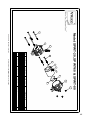
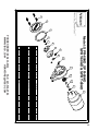
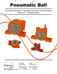
1
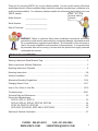
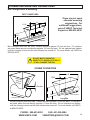
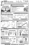
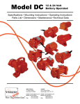
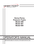
Small Impact Line Mounting Instructions • Operating Instructions Troubleshooting •Technical Data • Parts List Corporate HQ & Factory: 75 Stilson Road Wyoming, RI 02898 Phone: 800 633-0032 (401) 539-2392 Fax: (401) 539-2584 E-mail: [email protected] Website: www.vibco.com Western US: Phoenix, AZ 85254 Phone: 800 633-0032 (480) 596-1809 Fax: (480) 596-1614 Canada: 2215 Dunwin Drive Mississauga, ONT L5L 1X1 Phone: 800 465-9709 (905) 828-4191 Fax: (905) 828-5015 Southeastern US: Charlotte, NC 28277 Phone: 800 633-0032 (401) 539-2392 Fax: (401) 539-2584 Thank you for choosing VIBCO, Inc. for your vibration needs. You are now the owner of the finest small impact electric vibrator available today, backed by complete manufacturer confidence in its quality and dependability. For reference, please complete the information below about your new VIBCO vibrator. Thank you for Model Number: ____________________ Serial Number: ____________________ choosing VIBCO Vibrators. Date of Purchase: ____________________ WARNING: Failure to read and follow these installation instructions and safety precautions could result in personal injury, equipment damage, shortened service life or unsatisfactory equipment performance. All information in this document is vital to the proper installation and operation of the equipment. It is important that all personnel who will be coming in contact with this product thoroughly read and understand this manual. TABLE OF CONTENTS Warning Labels and Serial Number Tags .................................................................................. 2 Safety Instructions & Model Definitions ..................................................................................... 3 Mounting Instructions Checklist . ............................................................................................... 4 Mounting Instructions.............................................................................................................. 5-8 Vibrator Installation................................................................................................................ 9-12 Alternative Mounting Suggestions ...................................................................................... 13-14 Changing Output Force ...................................................................................................... 15-17 How to Fix a Crack in Your Bin............................................................................................ 18-19 Troubleshooting................................................................................................................... 20-21 Technical Data and Dimensions............................................................................................... 22 Parts Lists & Breakdowns SPR-20, SPR-21, SPRT-21 .............................................................................................. 23 SPR-40, SPR-60, SPR-80, SPRT-60, SPRT-80................................................................. 24 SPWT-20, SPWT-60, SPWT-80 ........................................................................................ 25 SPR-60HD, SPR-80HD, SPRT-60HD, SPRT-80HD........................................................... 26 Warranty & General Information . ............................................................................................ 27 PHONE : 800-633-0032 FAX: 401-539-2584 WWW.VIBCO.COM [email protected] WARNING LABELS AND SERIAL NUMBER TAGS WARNING! Do not operate with the cover removed. Whenever the cover is removed make sure that the power is turned off and cannot be turned on accidentally. Label Location: On body of vibrator. COUNTERWEIGHT WARNING LABEL WARNING! Make sure ground connections are completed. Before working on unit disconnect electric supply. Label Location: Wrapped around end of cord GROUND CONNECTION WARNING LABEL E L P VIBRATORS 800-633-0032 www.vibco.com RHODE ISLAND, USA -- ONTARIO, CANADA S/N: M SA AF3000000335.22222222222250000 MODEL: SCR-200 SERIAL NO: A5300000 VOLTS: 115 PHASE: 1 AMP: .8 CYCLE: 50/60 RPM: 0 - 4000 DUTY: SPECIAL Please have the information on this tag ready when ordering parts or contacting the technical service department at VIBCO. Label Location: On body of vibrator. Note: Always make sure that the vibrator does not run above the specified amperage for which the vibrator is wired. SERIAL NO. & SPECS TAG PHONE : 800-633-0032 FAX: 401-539-2584 WWW.VIBCO.COM [email protected] SAFETY INSTRUCTIONS WARNING: Failure to read and follow these installation instructions and safety precautions could result in personal injury, equipment damage, shortened service life or unsatisfactory equipment performance. All information in this document is vital to the proper installation and operation of the equipment. It is important that all personnel who will be coming in contact with this product thoroughly read and understand this manual. MODEL DEFINITIONS VIBCO’s model SPR line of electric vibrators utilize a shaded pole motor. To ensure a long operating life, they are constructed with ball bearings, not sintered bronze bearings, and have a low amperage draw. HD models have oversized bearings and shafts for use in severe duty applications. SPR-20 & -21: Open, Fan Cooled Motor For Clean, Dry, Non-Dusty Environments SPR-20 & 21 SPR-60 & -80: Totally Enclosed Fan-Cooled Motor NEMA Code TEFC, for Clean, Dry, Non-Dusty Environments HD: Heavy Duty Motors NEMA Codes TEFC OR TENV, for 24/7 Continous Operation SPR-40, -60 & -80 SPR-60 HD &80 HD SPRT: Totally Enclosed, Non-Ventilated Motor NEMA Code TENV, for Dusty Environments SPRT-21 SPWT: Watertight, Totally Enclosed, Non-Ventilated Motor NEMA Code 4, for Wash Down or Wet Environments SPWT-21 ,-60 & -80 SPRT: Totally Enclosed, Non-Ventilated Motor NEMA Code TENV, for Dusty Environments HD: Heavy Duty Motors NEMA Codes TEFC OR TENV, for 24/7 Continous Operation SPRT-40, -60 & -80 SPRT-60 HD & -80 HD PHONE : 800-633-0032 FAX: 401-539-2584 WWW.VIBCO.COM [email protected] MOUNTING INSTRUCTIONS CHECKLIST Factory warranty is void if vibrator is not installed per these instructions. DO NOT MOUNT VIBRATOR DIRECTLY TO SURFACE OF BIN!!! (IT WILL DAMAGE THE BIN) o Determine vibrator placement on bin. (See Vibrator Placement on Page 5) o Determine length of channel iron and position on side of bin. (Figure 1 on Page 6) o Determine style of mounting plate. (Figure 3 on Page 7) o Select method of STITCH welding mounting plate to channel iron. (Figure 4 on Page 7). o STITCH weld channel iron to bin. (See Welding Instructions on Page 8) o Attach vibrator to mounting plate. Check the mounting plate for warping. Secure firmly. DO NOT OVER TIGHTEN THE BOLTS. (See Vibrator Installation on Page 9) o Install safety chain or cable. (See Safety Chain Installation on Page 10) o Plug vibrator in using the NEC Standards. (See Figure 5 on Page 10) o Take a voltage reading at vibrator while running. VOLT _______ o Take an amp reading while vibrator is running. AMPS _______ o Compare readings to standard values. Is the force the vibrator produces sufficient? Do you need more or less? See service instructions. o FILL OUT WARRANTY CARD AND MAIL TO VIBCO!!!! If the these steps are followed, your vibrator will be installed properly and should give you years of trouble free service. If after reading these instructions you are still not sure how to mount your VIBCO Vibrator, call us for a custom VIBRA-Print™ diagram for your specific application. It will give you detailed placement instructions Is your bin or hopper made of a material not suitable for welding?? Call VIBCO now and ask about our VIBRA-Grip suction cup mount system. PHONE : 800-633-0032 FAX: 401-539-2584 WWW.VIBCO.COM [email protected] MOUNTING INSTRUCTIONS Vibrator Placement For coarse materials the vibrator should be mounted approximately 1/3 of the distance from the discharge opening to the top of the sloped portion of the bin. For fine materials place the vibrator 1/4 of the distance from the discharge to the top of the sloped portion of the bin. DO NOT MOUNT VIBRATOR DIRECTLY TO SURFACE OF BIN!!! (IT WILL DAMAGE THE BIN) 1/2 Rectangular Bin Conical Bin 1/4 TO 1/3 L PROPER PLACEMENT OF VIBRATOR IS ALWAYS LOCATED ON THE SLOPED PORTION OF THE BIN! L 1/4 TO 1/3 L Two Vibrators On A Single Bin Rectangular Bin (Normally used to clean out bin or for larger bins) L L 1/3 TO 1/4 L L 1/4 TO 1/3 L PHONE : 800-633-0032 FAX: 401-539-2584 WWW.VIBCO.COM [email protected] 1/2 L MOUNTING INSTRUCTIONS DETERMINING LENGTH OF CHANNEL IRON All of VIBCO’S SPR Electric Vibrators are designed to use standard 2” Channel Iron. However, 3” Channel Iron is also acceptable. 2” 1” 1/8” The thickness of your bin walls determines the minimum length of channel iron needed in order to successfully mount your vibrator. To find out what length of channel iron is needed for your application, refer to the chart below. Figure 1 Bin Wall Thickness Minimum Channel Iron Length (L) Less Than 1/8" (thin ) 12" to 24" on both sides of vibrator Greater Than 1/8" 6" to 8" on both sides of vibrator Note: Longer channel iron will not affect the vibrator performance, but total channel iron length should not exceed the length of the bin wall. L See Figure 1 for Dimensions L MOUNTING PLATES AVAILABLE FROM VIBCO Don’t have the time or the resources to manufacture your own mounting plates? VIBCO supplies mounting plates for all SPR Electric Vibrators. Choose the plate you need from the table below. Mounting bolts are included free of charge. Figure 2 VIBCO Model Mounting Plate Part No. SPR-20 SPR-21 SPR-40 SPM-1 SPM-1 SPM-2 SPR-80&80HD SPRT-21 SPR-60&60HD SPM-2 SPM-1 SPRT-80&80HD SPRT-60&60HD SPM-2 SPWT-21 SPWT-60 SPWT-80 SPWM SPWM SPWM Mounting Plates can be purchased with thru-holes standard (see Page 7.) For studded Mounting Plates add -ST to the part number when ordering. PHONE : 800-633-0032 FAX: 401-539-2584 WWW.VIBCO.COM [email protected] MOUNTING INSTRUCTIONS Determining Style of Mounting Plate For all SPR Vibrators, use 1/4 in. thick mounting plate. Figure 3 or Studded Thru Hole Mounting Plates for all SPR Vibrators can be purchased directly from VIBCO. Call (800) 633-0032. (See previous page for proper sizing & Part No.’s) Selecting Channel Iron Mounting Method Stitch Welding Mounting Plate to Channel Iron Always start and stop welds 1” from ends to prevent heat concentration. In accordance with the appropriate picture below, weld 2 to 3 inches, skip 1 to 2 inches and repeat until securely mounted. NOTE: length and spacing of stitch welds described here is different than that for mounting the channel iron to the bin. Figure 4 1a 4 3a 2 1b 5 6a 3b 6b Different Suggestions for Styles of Channel Iron 1a & b) Mounting plate welded to legs of channel iron (a-SPR, SPRT; b-SPWT). 2) Channel iron with holes drilled thru & nuts welded on back, or just holes drilled thru (SPR, SPRT). 3a & b) Mounting plate on face of channel iron & holes drilled or tapped thru (a-SPR, SPRT; b-SPWT). 4) Notch the channel for access to mounting bolts (SPR, SPRT). 5) Weld studs to back of channel (SPR, SPRT). 6a & b) Mounting plate welded to two angle iron stiffeners instead of channel iron (a-SPR, SPRT; b-SPWT). NOTE: for a list of alternate mounting brackets, see pages 35 & 36 of the VIBCO General Catalog. PHONE : 800-633-0032 FAX: 401-539-2584 WWW.VIBCO.COM [email protected] MOUNTING INSTRUCTIONS Stitch Welding Channel Iron to Bin DO NOT MOUNT VIBRATOR DIRECTLY TO SURFACE OF BIN !!! ( IT WILL DAMAGE THE BIN) Do you have a bin or hopper made of a material not suitable for welding?? Call VIBCO now and ask about our VIBRA-Grip suction cup mount system. EITHER 1/4 L (for fine materials) or 1/3 L (for coarse materials) FROM THE DISCHARGE PHONE : 800-633-0032 FAX: 401-539-2584 WWW.VIBCO.COM [email protected] VIBRATOR INSTALLATION It is now time to put the VIBCO vibrator in place. Make sure that it is secured tightly. Retighten the bolts after the first 10 to 15 minutes of operation and check them periodically to maintain proper tightness. Damage to both the bin and the vibrator can occur if the vibrator is not mounted securely. And remember, no matter how thick the mounting plate, it can still warp during welding, especially if VIBCO’s instructions are not followed 1) Place vibrator on mounting plate, then insert and tighten one bolt. See proper torque values listed to the right Step 1 2) After tightening the first bolt, look at the foot on the other side. If a gap exists between the mounting plate and foot of the vibrator, welding may have warped the channel iron. You will need to shim the space under the foot. BOLT SIZE 1/4" 5/16" 3/8" 1/2" 5/8" 3/4" TORQUE ft-lbs 13 25 48 115 145 260 Step 2 Shim DO NOT MOUNT VIBRATOR DIRECTLY TO SURFACE OF BIN !!! ( IT WILL DAMAGE THE BIN) DETAIL 3) After gap has been filled with shim(s), insert and tighten the second bolt Step 3 Never place vibrator directly on Angle Iron. it can cause flexing and the vibrator can overload and burn out. Angle Iron Channel Iron PHONE : 800-633-0032 FAX: 401-539-2584 WWW.VIBCO.COM [email protected] SAFETY CHAIN or WIRE ROPE INSTALLATION 1) After properly mounting your vibrator, determine a suitable location to anchor it to, then install an eyebolt as shown below. 2) Place thimbles around eyebolts, then loop the wire rope (1/8” dia.) around the thimble. Next place the two rope clips around the wire rope as shown in the figure below. First applying Clip A as shown, then applying Clip B as close as possible to the thimble. 3) Using a 3/8” drill, make a hole in the housing as shown below. Next place the thimble through the hole you drilled and loop the wire rope around the thimble. Secure the wire rope as shown in the figure below. First applying Clip A as shown, then applying Clip B as close as possible to the thimble. NOTE: Safety wire kit can be purchased from VIBCO, Part No. SC-1. A Step 1 B Equals Base Width Base Width Step 2 Thimble Assembly 3-3/4” (9 cm) Leave 4-6” (10-15 cm ) slack in the rope SAFETY CHAIN/WIRE ROPE IS NEEDED ONLY IF FALLING VIBRATOR CAN CAUSE BODILY HARM OR COSTLY DAMAGE A&B Foot of SPR Vibrator Step 3 Drill a 3/8” (10mm ) Hole Because standard SPR vibrators are 115 Volt Single Phase, with low amperage draw, they can be plugged into any standard NEMA 5 - 15R recepticle. 230V Single Phase models are also available, supplied with 3-Wire Pigtail wire (NOTE: black & white wires are power leads, green wire is ground). All SPR vibrators are equipped with internal thermal protection to prevent the vibrator from running over internal temperatures of 195 ºF (90ºC). To protect the vibrator from overload, a single phase overload protection should be installed in accordance with the amperage draw. Figure 5 After correctly mounting your vibrator and installing the safety chain or wire rope, you are ready to plug in your new VIBCO SPR Vibrator. PHONE : 800-633-0032 FAX: 401-539-2584 WWW.VIBCO.COM [email protected] 10 VIBRATOR INSTALLATION TAKE AN AMPERAGE DRAW WHILE THE VIBRATOR IS RUNNING Maximum Amperage The operating amperage of the vibrator should not exceed the value listed in the table below. If the vibrator runs above this amperage, it is most likely due to faulty installation. Check your mounting welds, and re-tighten bolts if necessary. Please refer to TROUBLESHOOTING on Page 20 for additional details. MODEL SPR-20 SPR-21 SPR-40 SPR-60&60HD SPR-80&80HD SPRT-21 SPRT-60&60HD SPRT-80&80HD SPWT-21 SPWT-60 SPWT-80 Volt Amps PH. 115/230 115/230 115/230 115/230 115/230 115/230 115/230 115/230 115/230 115/230 115/230 0.5/0.25 0.8/0.4 1.4/0.7 1.5/0.75 1.7/0.85 1.4/0.7 1.5/0.75 1.7/0.85 1.4/0.7 1.5/0.75 1.7/0.85 1 1 1 1 1 1 1 1 1 1 1 VPM 1600 3200 1600 3200 3200 3200 3200 3200 3200 3200 3200 60 Hz Force (lbs./ N) 15/67 20/89 25/111 60/267 80/356 20/89 60/267 80/356 20/89 60/267 80/356 VPM 1400 2800 1400 2800 2800 2800 2800 2800 2800 2800 2800 50 Hz Force (lbs./ N) 11/47 14/62 18/78 42/187 56/250 14/62 42/187 56/250 14/62 42/187 56/250 NOTE: Should overload occur, the vibrator will automatically stop and then restart after cooling down. Check serial tag for amperage draw, and perform an amperage test to see that the vibrator is running within specifications. You can also validate amperage draw by bench testing to see if the problem is in the mount or the vibrator itself. Refer to TROUBLESHOOTING section for details instructions. 150o F o 66 C Maximum Operating Temperature The skin temperature of the vibrator should not exceed 150oF (66oC). If skin temperature exceeds this, consult VIBCO for alternate solutions. PHONE : 800-633-0032 FAX: 401-539-2584 WWW.VIBCO.COM [email protected] 11 VIBRATOR INSTALLATION To Obtain Maximum Performance It is not necessary to operate the vibrator continuously or at maximum output to obtain maximum performance. Timers, etc. should be used to tune the timing of the vibrator for optimum performance and ensure a longer life. Continuous vs. Intermittent Operation SPR’s are rated for continuous duty. For bulk material bin applications, the vibrator should be used to reduce the material friction and increase flow, not as a feeder. Once the friction is reduced gravity flow will take over and the vibrator should be turned off. The vibrator can only induce as much flow through the hopper as the discharge will allow. Partially closed discharge gates, rotary air locks, screws conveyors, belt conveyors, etc. restrict the discharge rate of the material, so less time of vibration should be used in these instances. Over-vibration of hoppers with a restricted discharge can pack the material in the hopper, making it even more difficult to move. Vibrations per Minute (VPM) VIBCO’s SPR line of vibrators can be speed (or frequency) controlled by using a VIBCO speed adjuster (Model SPC for 115 volt units, Model SPC-230V for 230 volt units). The vibrators run at full frequency with direct line current. By connecting the vibrator to the speed adjuster, the frequency can be reduced (NOTE: this will also reduce the force). Models SPR-20 and SPR-21 are fully adjustable at any time. All other models need to start at full speed and then can be turned down to desired speed (frequency). The vibrator should never be operated if the discharge is closed, unless it is being used for cleaning out a near empty hopper. DON’T FORGET TO MAIL YOUR WARRANTY CARD! NTY RA WAR PHONE : 800-633-0032 FAX: 401-539-2584 WWW.VIBCO.COM [email protected] 12 ALTERNATIVE MOUNTING SUGGESTIONS Bin Configuration & Mounting Belt Conveyors These are just some alternate mounting suggestions. For additional suggestions, consult VIBCO Technical Support at 800-633-0032. W 1/3 W 1/3 L L Flow Direction Belt conveyors feed from the front. Vibrator should be placed 1/3 from the front. If 2 vibrators are used, place second one directly opposite 1/3 from the back. Do not operate back vibrator until bin is empty in front and the front vibrator has turned off. For more details, call VIBCO at 800-633-0032. DO NOT MOUNT VIBRATOR DIRECTLY TO SURFACE OF BIN !!! ( IT WILL DAMAGE THE BIN) Screw Conveyors W 1/3W Alterna te Side fo r Vibrato r As Close As Possible L Flow Direction 1/3L Flow Direction Long Bin Screw conveyors feed from back. Vibrator should be placed 1/3 from the back. If 2 vibrators are used, place 2nd one directly opposite 1/3 from the front. Do not operate front vibrator until bin is empty in back and the back vibrator has turned off. For more details, call VIBCO at 800-633-0032. PHONE : 800-633-0032 FAX: 401-539-2584 WWW.VIBCO.COM [email protected] 13 ALTERNATIVE MOUNTING SUGGESTIONS Chutes In order to successfully move material in a chute, the “angle of repose” of the material has to be known. It can be measured by pouring a cup of the material on a table. The angle between the table and the cone the material makes is the “angle of repose”. To move the material in the chute, it should be inclined no less than 1/2 of the “angle of repose” If this cannot be obtained, a feeder is necessary to move the material. For optimum performance follow these guidelines: • • • • Force (impact) needed on vibrator is equal to weight of chute + vibrator + maximum amount of material in chute. Chutes must have an inclination of at least 10o for vibrators to be able to move the material. If inclination is less, the chute has to be made into a feeder. Contact VIBCO for selecting the proper size vibrator. Chutes up to 6 ft. long can generally be handled by one vibrator mounted approximately 1/3 from the discharge. On chutes over 6 ft. long, two vibrators are needed. One should be placed 18 to 24 inches from the discharge. The other approximately in the middle of the chute. Since chutes are very sensitive to vibration, provision should be made to move the lower vibrator 6 inches in either direction. This could mean the difference between moving or not moving the material. L = Up to 6 FT. 1/3 L Place mounting plate 1/3 distance up the chute from the discharge. PHONE : 800-633-0032 FAX: 401-539-2584 WWW.VIBCO.COM [email protected] 14 CHANGING OUTPUT FORCE / ECCENTRIC SETTINGS SPR-21 and SPRT-21 have a single eccentric weight that produces maximum output. To reduce the output force, drill holes in the eccentric as necessary. VIBCO recommends drilling one small hole at a time and then testing the unit to see if it produces the desired results. Proceed with more or larger hole(s) as needed (Figure A). FIGURE A FACTORY SETTING MAXIMUM OUTPUT DRILL HOLE(S) IN ECCENTRIC TO REDUCE OUTPUT FORCE SPR-20, SPR-40, SPRT-60 and SPRT-80 have dual eccentrics factory set at the maximum output for the vibrator. To reduce the amount of vibration, loosen the set screw that holds the outer eccentric to the shaft and turn the outer eccentric in relation to the inner eccentric. Retighten the set screw. Figures B&C show maximum and minimum settings for each unit. FIGURE B MINIMUM SETTING (0 LBS. OF FORCE) FACTORY SETTING MAXIMUM OUTPUT NOTE: If you reset eccentrics on any model to INCREASE the force of the vibrator, you MUST take a new amperage draw reading to ensure your vibrator is still operating within the specified limits. FIGURE C MINIMUM SETTING (0 LBS. OF FORCE) FACTORY SETTING SPRT-60 FACTORY SETTING MAXIMUM OUTPUT SPRT-80 PHONE : 800-633-0032 FAX: 401-539-2584 WWW.VIBCO.COM [email protected] 15 CHANGING OUTPUT FORCE / ECCENTRIC SETTINGS continued SPR-60, SPR-80, SPR-60HD, SPR-80HD, SPRT-60HD and SPRT-80HD all have dual eccentrics factory set to the maximum allowable output for continuous duty use. NOTE: These models can only be run intermittently when set to higher than factory set output forces (maximum running time of 30 minutes in any one hour period). To reduce the force of the SPR-60 and the SPR-80, loosen the set screw that holds the outer eccentric to the shaft and turn the outer eccentric away from the inner eccentric. The less aligned that the two eccentrics are with one another, the less force output produced. Refer to Figure D for minimum settings. Retighten the set screw. To increase the force of the SPR-60 and the SPR-80, loosen the set screw that holds the outer eccentric to the shaft and turn the outer eccentric toward the inner eccentric. The closer in line that the two eccentrics are with one another, the more force output produced. Refer to Figure D for maximum settings. Retighten the set screw. FIGURE D NOTE: If you reset eccentrics on any model to INCREASE the force of the vibrator, you MUST take a new amperage draw reading to ensure your vibrator is still operating within the specified limits. To reduce the force of the SPR-60HD, SPR-80HD, SPRT-60HD and SPRT-80HD, remove the cap screw that holds the outer eccentric to the inner eccentric and turn the outer eccentric so that the hole marked #1 aligns with the threaded hole in the inner eccentric (see Figure E on next page). Replace the cap screw. PHONE : 800-633-0032 FAX: 401-539-2584 WWW.VIBCO.COM [email protected] 16 CHANGING OUTPUT FORCE / ECCENTRIC SETTINGS continued To increase the force of the SPR-60HD, SPR-80HD, SPRT-60HD and SPRT-80HD, remove the cap screw that holds the outer eccentric to the inner eccentric and turn the outer eccentric so that the hole marked #3 aligns with the threaded hole in the inner eccentric (see Figure E). Replace the cap screw. EXAMPLE: MODEL SPR-60HD Remove cap screw and adjust as shown below. Then replace the bolt and cover. Maximum Force Intermittent Duty Only CAP SCREW Factory Setting Maximum Setting for Continuous Duty CAP SCREW CAP SCREW Minimum Force Optimum Setting for Long Life of Vibrator FIGURE E NOTE: If you reset eccentrics on any model to INCREASE the force of the vibrator, you MUST take a new amperage draw reading to ensure your vibrator is still operating within the specified limits. SPWT-21, SPWT-60 and SPWT-80 have single internal eccentrics and are not adjustable. If you open the unit to attempt to reset the eccentrics you will compromise the watertight integrity and void your warranty. PHONE : 800-633-0032 FAX: 401-539-2584 WWW.VIBCO.COM [email protected] 17 HOW TO FIX A CRACK IN YOUR BIN Cracked Bin Shell Cracked bins are usually due to improper welding, improper mounting of the vibrator to the bin or to high an output force from the vibrator. If cracks have developed on your bin, follow the procedure detailed below to repair the cracks and eliminate any further cracking. Note: that cracks usually start at the ends of the channel iron. REPAIRING BIN CRACKS 1) Remove the vibrator from the mounting plate. DETAIL F 2) Locate where cracks stop. Take note of any places where the cracks may have branched off. It is very important that you located all the branches of the crack. 3) Drill holes at the end of every crack (on every branch). For average size cracks use a 1/8” to 1/4” drill. Remember that it is important is that the drill size be larger than the width of the crack. PHONE : 800-633-0032 FAX: 401-539-2584 WWW.VIBCO.COM [email protected] 18 4) Once holes are drilled, weld along all the cracks to the holes and then over the entire hole. Be sure to cover the entire crack and hole to prevent further damage. At least 4” ( 10cm ) past drill point At least 4” ( 10cm ) past drill point 5) Choose a length of angle iron to reinforce the area of the bin where cracking occurred. To determine on the appropriate length, make sure that the angle iron goes at least 4” ( 10 cm ) past the end of the outermost drill points / end of cracks. 6) After choosing an appropriate 1” length of angle iron, weld it in place. Starting 1” (2.5 cm) from the end of the angle iron, weld stitches 3-6” (7.5-15 cm ) long, leaving at least 3” (7.5 cm) between the stitches (see Page 8). Be sure to stop welds 1” ( 2.5 cm ) from the end of the angle iron. Angle Iron Be sure to weld both top and bottom of angle iron 7) Now you can remount vibrator on mounting plate. (Refer to Page 9 for proper Vibrator Installation Instructions) PHONE : 800-633-0032 FAX: 401-539-2584 WWW.VIBCO.COM [email protected] 19 TROUBLESHOOTING My Material STILL Isn’t Moving! 1. Did you put your vibrator in the right location? See Page 5 for proper vibrator placement. Did you mount your vibrator properly? See Page 6 for Mounting Instructions. 2. Do you have the right vibrator for the job. Does it provide enough force? Is it the right frequency? Still not sure? Call VIBCO Technical Support at 800-633-0032. The Vibrator won’t start! 1. Check power supply to unit. 2. Check motor continuity, if “open” motor winding is burned or has a short, replace motor. If you are unsure of how to check the continuity, call VIBCO Technical Support or consult a licensed electrical contractor. Bearings grind or make excessive noise, vibrator won’t run at full speed. 1. Are you running the vibrator in a dusty or dirty environment? You may need to switch to an enclosed model SPRT vibrator. 2. Are you running the vibrator in a wet or washdown environment? You may need to switch to an enclosed model SPWT vibrator. 3. Are you running the vibrator in a high temperature environment? You may need to switch to a fan cooled model SPR or a heavy duty HD model vibrator and install a heat mount. 4. Are you running the vibrator continously? You may need to switch to a heavy duty HD model vibrator. Vibrator stops running 1. Check power supply to unit. 2. Units are supplied with Internal Thermal Overload Protection (see Page 11). If the winding temperature of the unit exceeds 195ºF (90ºC), the vibrator will shut down and restart after it cools down. Repeated stops and starts of the vibrator will overload the vibrator motor and will burn out its windings. To protect the vibrator from overloads, install a single phase overload protection in the line. Check to make sure that the vibrator is mounted securely, and that there are no cracks in the bin wall. 3. If unit does not restart after cooling down, check motor continuity. If “open” motor winding is burned or has a short, replace motor. If you are unsure of how to check the continuity, call VIBCO Technical Support or consult a licensed electrical contractor. 4. If vibrator DOES start after cooling down, take an amperage reading of the vibrator. If amperage is in excess of what is listed on Serial No. & Specs Tag (or chart on Page 11) make sure that the mounting bolts are still secure or look for cracks in your welds or bin wall. (See details below) If your mount is OK, then the vibration may be too intense for the hopper structure. You may need to reduce the intensity (force) of vibration to reduce the amperage draw of the vibrator (Pages 12, 15 – 17), or reduce the time of vibration to reduce the temperature rise. (Page 12) NOTE: Proper force for a full hopper can be excessive for an empty or near empty hopper. Cracks have developed on bin wall The improper welding of a vibrator to bin stiffeners often results in fatigue cracks in the bin. This can be repaired to prevent further cracking by properly welding stiffeners to the bin side. To accomplish this see Welding Instructions on Pages 18-19. PHONE : 800-633-0032 FAX: 401-539-2584 WWW.VIBCO.COM [email protected] 20 TROUBLESHOOTING How do I know if I welded everything correctly? To check if you welded everything correctly see if the mount affects the performance of the vibrator. VIBCO recommends you get a reading of the amperage draw of the vibrator before it is bolted to the channel iron on your bin. Place the vibrator on any soft material you might have (pillows, seat cushions, etc.) Turn the vibrator on and turn the control box dial to its maximum setting. Take an amperage reading and compare it to the values found on Page 12 (or on the Serial # & Specs Tag on the unit). If the two values match, reinstall the vibrator according the instructions on Page 9 and take another amperage reading while the vibrator is running. If the amperage reading is now still too high then: 1) Check that your bolts have been tightened to the torque specified on Page 9. 2) Make sure the vibrator has been properly shimmed and stabilized. 3) If both of these conditions are satisfied, then reinspect your welds to see if there are any additional cracks. Repair them according to instructions on Pages 18-19. The vibrator should not be moving excessively when in operation. If you are able to read the Serial # & Specs Tag, then the amount of motion is acceptable. If you cannot, refer to the mounting instructions to fix the problem or consult VIBCO. 800-633-0032 PHONE : 800-633-0032 FAX: 401-539-2584 WWW.VIBCO.COM [email protected] 21 TECHNICAL DATA & DIMENSIONS Technical Data Force Impact MODEL Bin Capacity Speed Wt. lbs. kg. * dB PH. VPM Enclosure Option 115/230 0.5/0.25 1 1600 Open Yes 3 1.4 45 890 115/230 0.8/0.4 1 3200 Open Yes 3 1.4 48 1112 115/230 1.4/0.7 1 1600 Yes 7 3.2 45 Partly 7 3.2 48 Partly 7 3.2 50 lbs. N lbs. N SPR-20 15 67 150 667 SPR-21 20 89 200 SPR-40 25 111 250 Amps Adj. Speed Volt Tot. Encl. & Fan Cooled SPR-60&60HD 60 267 600 2669 115/230 1.5/0.75 1 3200 SPR-80&80HD 80 356 800 3558 115/230 1.7/0.85 1 3200 SPRT-21 20 89 200 890 115/230 1.4/0.7 1 3200 Tot. Encl. Yes 3 1.4 45 SPRT-60&60HD 60 267 600 2669 115/230 1.5/0.75 1 3200 Tot. Encl. Partly 7 3.2 48 SPRT-80&80HD 80 356 800 3558 115/230 1.7/0.85 1 3200 Tot. Encl. Partly 7 3.2 50 SPWT-21 20 89 200 890 115/230 1.4/0.7 1 3200 Watertight Yes 7 3.2 45 SPWT-60 60 267 600 2669 115/230 1.5/0.75 1 3200 Watertight Partly 7 3.2 48 SPWT-80 80 356 800 3558 115/230 1.7/0.85 1 3200 Watertight Partly 7 3.2 50 *dB at 3' ( 1meter ) on A scale N = Centrifugal force in Newtons MODELS SPR & SPRT MODEL SPWT Dimensions A MODEL SPR-20, 21, SPRT-21 SPR-40, 60, 80 & HD SPRT-60, 80 & HD SPWT-21, 60, 80 B L W mm Inch mm Inch mm Inch mm Inch mm 4 5 5 4 3/4 102 127 127 121 2 3/4 70 3/8 3/8 3/8 3/8 10 10 10 10 5 7 5 1/2 5 3/8 127 178 140 137 5 6 6 5 1/2 127 152 152 140 Inch mm Inch mm Inch mm Inch mm 1/2 1/4 1/4 1/2 89 108 108 165 3 1/2 4 4 3/16 4 1/2 89 102 106 114 11 13 13 16 4 5 7/8 4 1/2 - 102 149 114 - H SPR-20, 21, SPRT-21 SPR-40, 60, 80 & HD SPRT-60, 80 & HD SPWT-21, 60, 80 C* Inch 3 4 4 6 D E 7/16 1/2 1/2 5/8 F * Bolt Size PHONE : 800-633-0032 FAX: 401-539-2584 WWW.VIBCO.COM [email protected] 22 PHONE ORDER: 800-633-0032 FAX: 401-539-2584 WWW.VIBCO.COM [email protected] 23 PHONE ORDER: 800-633-0032 FAX: 401-539-2584 WWW.VIBCO.COM [email protected] 24 PHONE ORDER: 800-633-0032 FAX: 401-539-2584 WWW.VIBCO.COM [email protected] 25 PHONE ORDER: 800-633-0032 FAX: 401-539-2584 WWW.VIBCO.COM [email protected] 26 WARRANTY AND GENERAL INFORMATION Warranty All warranty claims must be submitted to VIBCO for approval prior to any repairs being done. Warranty claims will be processed at VIBCO factory. Failure to do so will void any and all warranty coverage. Errors, Shortages and Complaints Complaints concerning goods received or errors should be made at once. Claims must be made within five days after receipt of goods. Clerical errors are subject to correction. Returning Parts Parts should not be returned to VIBCO without prior authorization. Call VIBCO’s customer service department at 800-633-0032 (800-465-9709 in Canada) for a Return Goods Authorization (RGA) number. A return authorization will be faxed to you. Return shipping must be prepaid. Material returned may be subject to a 10% restocking fee. All returned shipments should clearly display your name, address and original invoice number on packing slip supplied by VIBCO to ensure proper credit. Orders for equipment built to specifications which vary from VIBCO’s standard units are not returnable. Responsibility VIBCO cannot be responsible for delays due to strikes, accidents, negligence of carriers or other causes beyond our control. Freight Claims Should you receive a shipment from VIBCO which was damaged in transit, file your claim with the carrier immediately. All parts sold by VIBCO are on the basis of F.O.B. Wyoming, Rhode Island. Product Changes VIBCO reserves the right to make changes in pattern, design or materials when deemed necessary, without prior notice or obligation to make corresponding changes in previous models. Price Changes Prices are subject to change without notice. Ordering Spare Parts Parts can be ordered through authorized distributors or directly from VIBCO. The following data should be provided when ordering: From vibrator: From spare parts list: Shipping instructions: Model of unit. Reference number, part number, description and quantity required. Specify shipping point and method of shipping. PHONE : 800-633-0032 FAX: 401-539-2584 WWW.VIBCO.COM [email protected] 27 Corporate HQ and Factory SPR-SVC3