1
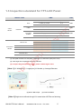
c. In gy lo no ch Te P User’s Manual IC O HMI-043T-B DMP Vortex86 EXm Processor Compact Panel PC with 4.3” Touchscreen HMI-043T-EM41N-B HMI-043T-EM41B-B HMI-043T-EM42N-B HMI-043T-EM42B-B HMI-043T User’s Manual IUMHMI043T-01 Ver.1.0A Jul, 2014 i REVISION VERSION 2015/2/1 Version 1.0A DESCRIPTION New Release IC O P Te ch no lo gy In c. DATE HMI-043T-B User’s Manual IUMHMI043T-B Ver.1.0A Feb, 2015 i COPYRIGHT The information in this manual is subject to change without notice for continuous improvement in the product. All rights are reserved. The manufacturer assumes no responsibility for any inaccuracies that may be contained in this document, and makes no commitment to update or to keep current the information contained in this manual. c. No part of this manual may be reproduced, copied, translated or transmitted, in whole or in part, in any form or by any means without the prior written permission of the ICOP Technology Inc. gy In Copyright 2015 ICOP Technology Inc. Manual # IUMHMI043T-B Ver.1.0A Feb, 2015 lo TRADEMARKS ACKNOWLEDGMENT no Vortex86EXm is the registered trademark of DMP Electronics Inc. Other brand names or product names appearing in this document are the properties and registered trademarks of their respective owners. All names mentioned herewith are served for identification purpose only. ch For more detailed information or if you are interested in other ICOP products, please visit our official websites at: USA: www.icoptech.com Japan: www.icop.co.jp GmbH: www.icoptech.eu China: www.icop.com.cn P Te Global: www.icop.com.tw O For technical support or demo images of operating systems download, please visit our websites at: IC ICOP Technical Resource: http://tech.icop.com.tw/ Software Support: http://www.icoptech.net/ This Manual is for the HMI-043T. Box Series HMI-043T-B User’s Manual IUMHMI043T-B Ver.1.0A Feb, 2015 ii SAFETY INFORMATION Read these Safety instructions carefully. Please carry the unit with both hands, handle carefully. Make sure the voltage of the power source is correct before connecting the equipment to the power outlet. In Input voltage rated +12 ~ 24VDC (HMI-043T Box Series) c. Do not expose your Panel PC to rain or moisture in order to prevent shock and fire hazard. Operating temperature between -20~+60°C (-4F~+140°F). gy Keep HMI-043T away from humidity. Never touch un-insulated terminals or wire unless your power adaptor is disconnected. no lo Locate your Panel PC as close as possible to the socket outline for easy access and to avoid force caused by entangling of your arms with surrounding cables from the Panel PC. USB connectors are not supplied with Limited Power Sources. WARNING! Te ch If the equipment is not used for a long time, disconnect it from the power source to avoid damage by transient overvoltage. IC O P DO NOT ATTEMPT TO OPEN OR TO DISASSEMBLE THE CHASSIS (ENCASING) OF THIS PRODUCT. PLEASE CONTACT YOUR DEALER FOR SERVICING FROM QUALIFIED TECHNICIAN. HMI-043T-B User’s Manual IUMHMI043T-B Ver.1.0A Feb, 2015 iii Content Content ............................................................................................................................. iv Ch. 1 General Information ................................................................................................. 1 1.1 Product Description ................................................................................................. 2 c. 1.2 Product Specifications ............................................................................................. 3 1.3 Inspection standard for TFT-LCD Panel .................................................................. 5 In 1.4 Product Dimensions ................................................................................................ 7 1.5 Ordering Information................................................................................................ 8 gy Ch. 2 System Installation .................................................................................................. 9 2.1 CPU Board Outline .................................................................................................10 lo 2.2 Connector Summary............................................................................................... 11 2.3 Connector Pin Assignments ...................................................................................12 no 2.4 External I/O Overview.............................................................................................15 Ch. 3 Driver Installation ....................................................................................................16 ch 3.1 HMI-043T Development Note .................................................................................18 IC O P Te Warranty...........................................................................................................................19 HMI-043T-B User’s Manual IUMHMI043T-B Ver.1.0A Feb, 2015 iv c. In gy lo no ch 1 Te Ch. O P General Information 1.1 Product Description IC 1.2 Product Specifications 1.3 Inspection standard for TFT-LCD Panel 1.4 Product Dimensions 1.5 Odering Information HMI-043T-B User’s Manual IUMHMI043T-B Ver.1.0A Feb, 2015 1 1.1 Product Description ICOP Technology Inc. is proudly going to release a brand new HMI, which offers fanless design, low power consumption, and IP65 front panel. The HMI-043T is powered by DMP Vortex86Exm SoC, the new generation SoC of Vortex86 family, which is included 128MB/256MB memory and eMMC Flash memory. The resistive touch panel with LED c. backlight TFT LCD increases operation convenience and visibility in outdoor environments. In The ultra-compact and thin exterior design is perfect for the present demanding embedded and productive applications. gy The new HMI-043T inherited PDX/PMX-series’ smooth appearance and ultra-texture aluminum exterior design to make your industrial applications look more stylish. The versatile I/O lo ports, 10/100Mps Ethernet, RS/232/485 , GPIO and Can bus etc. can fulfill fundamental functions. Our consistent advantages feature stable performance, extended working temperature no support, low power consumption and fanless design. The open frame model can be accommodated connectivity requirements to industrial machine platforms and industrial ch automation equipment’s needs. Te HMI-043T is not only supporting DOS, Linux, and Windows Embedded CE, but also compatible with Arduino platform, which is an open-source electronics prototyping platform based on flexible, easy to use hardware and software to meet ready-to-market demand and IC O P provide competitive advantages for customers. HMI-043T-B User’s Manual IUMHMI043T-B Ver.1.0A Feb, 2015 2 1.2 Product Specifications HARDWARE SPECIFICATIONS CPU DMP Vortex86Exm 400MHz BIOS Coreboot BIOS c. L1:16KB I-Cache, 16KB D-Cache Cache 128MB / 256MB DDRIII onboard Nand-Flash 512MB/1GB/2GB eMMC onboard (Optional) Integrated 10/100Mbps Ethernet Network gy Memory In L2: 4-way, 128KB L2 Cache lo Support IEEE 802.3AT, PoE/PD (Optional) Serial Interface RS-485 x 1 no RS-232 x 1 ch Can bus x 1 (Optional) USB ports (Ver2.0) x 1 Te USB P MECHANICAL & ENVIRONMENT O Power Requirement IC Power Consumption Operating Temperature +12 ~ 24VDC +12V@1A 0~+50°C (+32~+122°F) / -20~+60°C (-4~+140°F) Storage Temperature -30~+70°C (-22~ +158°F) Operating Humidity 0% ~ 90% Relative Humidity, Non-Condensing Dimensions 116.4 x 94.4 x 34.3mm (4.58 x 3.71 x 1.35 inches) Weight 300g HMI-043T-B User’s Manual IUMHMI043T-B Ver.1.0A Feb, 2015 3 LCD SPECIFICATIONS Display Type 4.3” WQVGA TFT LCD Backlight Unit LED Display Resolution 480(W) x 272(H) 2 2 350 cd/m Contrast Ratio 450 : 1 Display Color 16.7M Pixel Configuration R.G.B Vertical Stripe Viewing Direction 6 o’clock Viewing Angle Vertical 120 , Horizontal 140 gy o lo o no TOUCHSCREEN Analog Resistive Resolution Continuous ch Type Transmittance Controller 3H / Anti-Glare 80% Te Surface Properties PS/2 interface DOS/Linux / WinCE 1 million IC O P Software Driver Durability In c. Luminance (cd/m ) HMI-043T-B User’s Manual IUMHMI043T-B Ver.1.0A Feb, 2015 4 1.3 Inspection standard for TFT-LCD Panel DEFECT TYPE LIMIT Ignore 0.15mm≦φ≦0.5mm N≦4 0.5mm<φ N=0 0.03mm<W≦0.1mm, L≦5mm N≦3 VISUAL DEFECT INTERNAL 1.0mm<W, 1.5mm<L Ignore In 0.15mm≦φ≦0.5mm N≦2 0.5mm<φ It’ OK if mura is slight visible through 6%ND filter A Grade DARK DOT ELECTRICAL DEFECT C Area O Area N≦0 N≦2 N≦2 TOTAL DOT B Grade Total C Area O Area Total Note3 N≦2 N≦2 N≦3 N≦5 Note2 N≦5 N≦8 lo BRIGHT DOT N≦3 N≦3 N≦3 N≦5 N≦6 N≦8 Note2 N≦1 pair N≦1 pair N≦1 pair N≦1 pair Note4 N≦4 LINE DEFECT N≦1 pair NOT ALLOWED ch THREE OR MORE ADJACENT DOT N≦0 no TWO ADJACENT DOT NOT ALLOWED (1) One pixel consists of 3 sub-pixels, including R, G, and B dot. (Sub-pixel = Dot) Te (2) Little bright Dot acceptitable under 6% ND-Filter. (3) If require G0 grand (Total dot N≦0), please contact region sales. IC O P [ Note 1 ] W: Width[mm]; L: Length[mm]; N: Number; φ: Average Diameter. (a) White / Black Spot (b) Polarizer Bubble [ Note 2 ] Bright dot is defined through 6% transmission ND Filter as following. HMI-043T-B User’s Manual Note1 N=0 gy Mura Note1 N=0 φ<0.15mm POLARIZER BUBBLE Note1 c. φ<0.15mm SPOT FIBER Note IUMHMI043T-B Ver.1.0A Feb, 2015 5 c. no lo gy In [ Note 3 ] Display area C Area: Center of display area O Area: Outer of display area ch [ Note 4 ] Judge the defect dot and the adjacent dot as following. Allow below (as A, B, C and D status) adjacent defect dots, including bright and dark adjacent dot. And they will be counted 2 defect dots in total quantity. Te A C P RG RG RG RG RG RG R Adjacent Dot O RG RG RG RG RG RG R Defect Dot IC RG RG RG RG RG RG B D The defects that are not defined above and considered to be problem shall be reviewed and discussed by both parties. Defects on the Black Matrix, out of Display area, are not considered as a defect or counted. HMI-043T-B User’s Manual IUMHMI043T-B Ver.1.0A Feb, 2015 6 IC O P Te ch no lo gy In c. 1.4 Product Dimensions HMI-043T-B User’s Manual IUMHMI043T-B Ver.1.0A Feb, 2015 7 1.5 Ordering Information DESCRIPTION HMI-043T-EM41B-B01 4.3" HMI w/128MB/512MB eMMC /USB/RS232/485/DC+12-24V HMI-043T-EM41B-B02 4.3" HMI w/128MB/512MB eMMC /USB/POE/RS232/485/DC+12-24V HMI-043T-EM41B-BC1 4.3" HMI w/128MB/512MB eMMC/USB/CAN/DC+12-24V gy In c. PART NUMBER PACKING LIST PACKAGE HMI-043T-EM41B-B01 HMI-043T-EM41B-B01 *1 HMI-043T-EM41B-B02 HMI-043T-EM41B-B02 *1 HMI-043T-EM41B-BC1 HMI-043T-EM41B-BC1 *1 IC O P Te ch no lo PART NUMBER HMI-043T-B User’s Manual IUMHMI043T-B Ver.1.0A Feb, 2015 8 c. In gy lo no ch 2 Te Ch. P System Installation O 2.1 CPU Board Outline IC 2.2 Connector Summary 2.3 Connector Pin Assignments 2.4 Connector I/O Overview HMI-043T-B User’s Manual IUMHMI043T-B Ver.1.0A Feb, 2015 9 gy In c. 2.1 CPU Board Outline J1A no lo J1B Te ch HMI-043T-B CPU Board IC O P J8 J2 J9 J3 LAN1 J6 J5 HMI-043T-B I/O Board HMI-043T-B User’s Manual IUMHMI043T-B Ver.1.0A Feb, 2015 10 2.2 Connector Summary Description Type of Connections Pin # J1A Expansion slot 1.27mm 32x2-pin female box header 64-pin J1B Expansion slot 1.27mm 32x2-pin female box header 64-pin J2 USB External USB Connector 6-pin J3 USB External USB Connector J5 COM2 RS232/485 or CAN bus External D-Sub Male Connector 9-pin J6 COM2: RS232/485 setting Pin Header, 2.54mm, 1x2 2-pin J8 SD Card Slot (Optional) Internal SD Card Socket J9 Power Terminal Connector External Power Plug In gy lo no Ethernet External RJ45 Connector 8-pin Te P O IC HMI-043T-B User’s Manual IUMHMI043T-B Ver.1.0A Feb, 2015 6-pin 3-pin ch LAN1 c. No. 11 2.3 Connector Pin Assignments J1A/J1B: Expansion Slot J1A2 J1B1 J1B2 Signal Name Pin# Signal Name Pin# Signal Name Pin# Signal Name 1 RSTDRV 2 GND 1 VCC_IN 2 VCC_IN 3 GP00 4 GP01 3 GP70 4 GP71 5 GP02 6 GP03 5 GP72 6 GP73 7 GP04 8 GP05 7 GP74 8 GP75 9 GP06 10 GP07 9 GP76 10 GP77 11 GP90 12 GP91 11 GP60 12 GP61 13 GP92 14 GP93 13 GP62 14 GP63 15 GP94 16 GP95 15 GP64 16 GP65 17 GP96 18 GP97 17 GP66 18 GP67 19 GND 20 GND 19 GND 20 GND 21 USBD1- 22 USBD2- 21 GP50 22 GP51 23 USBD1+ 24 USBD2+ 23 GP52 24 GP53 25 AGND 26 AGND 25 GP54 26 GP55 27 ADC_0 28 ADC_1 27 GP56 28 GP57 29 ADC_2 30 ADC_3 29 GP40 30 GP41 31 ADC_4 32 ADC_5 31 GP42 32 GP43 33 ADC_6 34 ADC_7 33 GP44 34 GP45 35 GND 36 GND 35 GP46 36 GP47 37 SATA_TX- 38 SATA_RX- 37 GND 38 GND 39 SATA_TX+ 40 SATA_RX+ 39 GP30 40 GP31 GND 42 HSYNC 41 GP32 42 GP33 VGA_R 44 VSYNC 43 GP34 44 GP35 VGA_G 46 PCIRST- 45 GP36 46 GP37 VGA_B 48 RESET- 47 GP20 48 GP21 49 GND 50 GND 49 GP22 50 GP23 51 LANTX- 52 LANRX- 51 GP24 52 GP25 53 LANTX+ 54 LANRX+ 53 GP26 54 GP27 55 VBATT 56 VCC1.8_OUT 55 GND 56 GND 57 GP80 58 GP81 57 GP10 58 GP11 59 GP82 60 GP83 59 GP12 60 GP13 61 GP84 62 GP85 61 GP14 62 GP15 63 GP86 64 GP87 63 GP16 64 GP17 45 HMI-043T-B User’s Manual In gy lo ch Te IC 47 P 43 O 41 c. Pin# no J1A1 IUMHMI043T-B Ver.1.0A Feb, 2015 12 c. In gy lo no ch Te P O IC HMI-043T-B User’s Manual IUMHMI043T-B Ver.1.0A Feb, 2015 13 J2/J3: USB J6: COM2: RS232/485 setting Pin # Signal Name Pin # Signal Name 1 VCC OPEN ENABLE RS-232 2 USB0- CLOSE ENABLE RS-485 3 USB0+ 4 GND 5 GGND 6 GGND Pin # J5: COM2 RS-232/485 n Name # # DCD2/ 1 2 RS485- Signal Name RXD2/ RS485+ TXD2 4 DTR2 5 GND 6 DSR2 7 RTS2 8 CTS2 9 RI2 GND 3 FG Pin Signal Pin Signal # Name # Name 1 FTXD+ 2 FTXD- 3 FRXIN+ 4 NC 5 NC 6 FRXIN- 7 NC 8 NC Te ch 3 2 LAN1 lo Pi Signal no n +12~24V gy (Change setting by J6 Jumper) Pi Signal Name In 1 c. J9: Power Connector DC-IN 24V P J5: CAN bus (Optional) O Pi n IC # Signal Name Pi n # 1 2 3 4 5 6 7 CAN H Signal Name CAN L 8 9 HMI-043T-B User’s Manual IUMHMI043T-B Ver.1.0A Feb, 2015 14 gy In c. 2.4 Connector I/O Overview no 10/100Mbps Ethernet USB 2.0 PORT RS-232/485 or CAN bus IC O P Te ch Power Switch lo SD Slot (Optional) HMI-043T-B User’s Manual IUMHMI043T-B Ver.1.0A Feb, 2015 15 c. In gy lo no ch Te P 3 O IC Ch. Driver Installation 3.1 HMI-043T Development Note HMI-043T-B User’s Manual IUMHMI043T-B Ver.1.0A Feb, 2015 16 VGA Vortex86VGA is a programmable VGA controller in 22mm x 16mm LQFP 128 package. It integrates a PCIe bridge controller and a VGA controller with 4M-Byte Pseudo SRAM memory (16-bit data width). It also c. incorporates 3.3V DVO digital interfaces to support a third party LVDS/TMDS transmitter. LAN In The Vortex86DX2 processor is integrated 10/100Mbps Ethernet controller gy that supports both 10/100BASE-T and allows direct connection to your 10/100Mbps Ethernet based Local Area Network for full interaction with local servers, wide area networks such as the Internet. I/O and IRQ settings can be done by software with the supplied utility no lo software, or it can be set for Plug and Play compatibility. The controller supports: Half / Full-Duplex Ethernet function to double channel bandwidth, auto media detection. ch OPERATING SYSTEM SUPPORT The HMI-043T provides the VGA and LAN drivers for DOS, Linux, and Te Windows CE, Please get the drivers from ICOP technical support URL: tech.icop.com.tw HMI-043T is an open-source embedded platform based on Vortex86EXm IC O P SoC, easy-to-use hardware and software integrated. This platform can support many x86 O/S as well as those running on the original Arduino base system. HMI-043T-B User’s Manual IUMHMI043T-B Ver.1.0A Feb, 2015 17 3.1 HMI-043T Development Note < WINDOWS DEVELOPMENT GUIDE > Windows Embedded CE 6.0 BSP and development notes, please visit technical website to get more information at http://tech.icop.com.tw/. c. < LINUX INSTALLATION NOTE> IC O P Te ch no lo gy In Please visit Linux technical website to get more information at ftp://ftp.dmp.com.tw/Linux_DEMO/Vortex86_Linux_Support_List_revised. htm. HMI-043T-B User’s Manual IUMHMI043T-B Ver.1.0A Feb, 2015 18 Warranty In c. This product is warranted to be in good working order for a period of one year from the date of purchase. Should this product fail to be in good working order at any time during this period, we will, at our option, replace or repair it at no additional charge except as set forth in the following terms. This warranty does not apply to products damaged by misuse, modifications, accident or disaster. Vendor assumes no liability for any damages, lost profits, lost savings or any other incidental or consequential IC O P Te ch no lo gy damage resulting from the use, misuse of, originality to use this product. Vendor will not be liable for any claim made by any other related party. Return authorization must be obtained from the vendor before returned merchandise will be accepted. Authorization can be obtained by calling or faxing the vendor and requesting a Return Merchandise Authorization (RMA) number. Returned goods should always be accompanied by a clear problem description. All Trademarks appearing in this manuscript are registered trademark of their respective owners. All Specifications are subject to change without notice. © ICOP Technology Inc. 2015 HMI-043T-B User’s Manual IUMHMI043T-B Ver.1.0A Feb, 2015 19