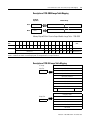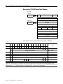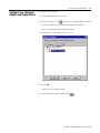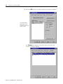
1
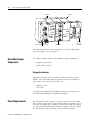
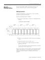
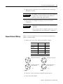
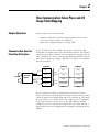
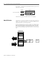
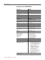
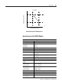
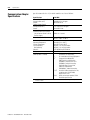
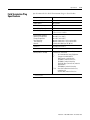
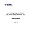
FlexArmor
1798-ADN (Contains information
on 1798-IB4, -IB8, -OB4E, -OB8E,
-IB4D, -IE4, -OE2)
User Manual
Important User Information
Because of the variety of uses for the products described in this
publication, those responsible for the application and use of these
products must satisfy themselves that all necessary steps have been
taken to assure that each application and use meets all performance
and safety requirements, including any applicable laws, regulations,
codes and standards. In no event will Rockwell Automation be
responsible or liable for indirect or consequential damage resulting
from the use or application of these products.
Any illustrations, charts, sample programs, and layout examples
shown in this publication are intended solely for purposes of
example. Since there are many variables and requirements associated
with any particular installation, Rockwell Automation does not assume
responsibility or liability (to include intellectual property liability) for
actual use based upon the examples shown in this publication.
Allen-Bradley publication SGI-1.1, Safety Guidelines for the
Application, Installation and Maintenance of Solid-State Control
(available from your local Rockwell Automation office), describes
some important differences between solid-state equipment and
electromechanical devices that should be taken into consideration
when applying products such as those described in this publication.
Reproduction of the contents of this copyrighted publication, in whole
or part, without written permission of Rockwell Automation, is
prohibited.
Throughout this publication, notes may be used to make you aware of
safety considerations. The following annotations and their
accompanying statements help you to identify a potential hazard,
avoid a potential hazard, and recognize the consequences of a
potential hazard:
WARNING
!
ATTENTION
!
IMPORTANT
Identifies information about practices or
circumstances that can cause an explosion in a
hazardous environment, which may lead to personal
injury or death, property damage, or economic loss.
Identifies information about practices or
circumstances that can lead to personal injury or
death, property damage, or economic loss.
Identifies information that is critical for successful
application and understanding of the product.
FlexArmor and RSNetWorx for DeviceNet are trademarks of Rockwell Automation.
MicroSoft Windows is a registered trademark of Microsoft Corporation.
Summary of Changes
New Modules Information
In this version of the FlexArmor™ User Manual information was
added about the following three FlexArmor modules:
• 1798-IB4D,
• 1798-IE4, and
• 1798-OE2.
Communication and mapping information about these modules are
contained in chapter 2. Configuration information is found in chapter
3.
1
Publication 1798-UM001B-EN-P - November 2002
Summary of Changes
2
Notes:
Publication 1798-UM001B-EN-P - November 2002
Preface
Introduction
Use this manual to install, communicate with, map, configure, and
troubleshoot the FlexArmor system.
Contents
You will find the following information in this manual:
For information about
installing your DeviceNet adapter module
how communication takes place and I/O image mapping
how to configure your DeviceNet adapter
troubleshooting
module specifications
See
Chapter 1
Chapter 2
Chapter 3
Chapter 4
Appendix A
Audience
This manual is intended for engineers and technicians who are
installing, programming, and maintaining a FlexArmor system.
What We assume
We assume you:
• know each of your device’s I/O parameters and requirements
• are familiar with RSNetWorx for DeviceNet™
• are familiar with the Microsoft® Windows® environment
Common Techniques Used
in This Manual
1
The following conventions are used throughout this manual:
• Bulleted lists provide information, not procedural steps.
• Numbered lists provide sequential steps.
• Pictures of keys and/or screens represent the actual keys you
press or the screens you use.
• Actions you must perform appear in bold text. For example:
Click View to display the EDS file.
Publication 1798-UM001B-EN-P - November 2002
Preface
2
Rockwell Automation
Support
Before you contact Rockwell Automation for technical assistance, we
suggest you please review the troubleshooting information contained
in chapter 4 of this publication first.
If the problem persists, call your local distributor or contact Rockwell
Automation in one of the following ways:
Phone
Internet
United
States/Canada
1.440.646.5800
Outside United
States/Canada
You can access the phone number for your country via the
Internet:
1. Go to http://www.ab.com
2. Click on Product Support
(http://support.automation.rockwell.com)
3. Under Support Centers, click on Contact Information
⇒
1. Go to http://www.ab.com
2. Click on Product Support
(http://support.automation.rockwell.com)
Your Questions or Comments on this Manual
If you find a problem with this manual, please notify us of it on the
enclosed How Are We Doing form found in the back of the manual.
Publication 1798-UM001B-EN-P - November 2002
Table of ContentsTable of Contents
Chapter 1
Install Your DeviceNet Adapter
Module
Chapter Objectives . . . . . . . . . . . . . . . . . . . . . . . . . . . . . .
About the FlexArmor System . . . . . . . . . . . . . . . . . . . . . . .
DeviceNet Adapter Components . . . . . . . . . . . . . . . . . . . .
Diagnostic Indicators . . . . . . . . . . . . . . . . . . . . . . . . . .
Power Requirements . . . . . . . . . . . . . . . . . . . . . . . . . . . . .
Mount the FlexArmor Platform. . . . . . . . . . . . . . . . . . . . . .
Mounting Instructions . . . . . . . . . . . . . . . . . . . . . . . . .
Set the Network Address Switch on the DeviceNet Adapter.
Install Your FlexArmor DeviceNet Adapter Module. . . . . . .
Connect External Wiring . . . . . . . . . . . . . . . . . . . . . . . . . .
1-1
1-1
1-2
1-2
1-2
1-3
1-3
1-4
1-4
1-5
Chapter 2
How Communication Takes Place Chapter Objectives . . . . . . . . . . . . . . . . . . . . . . . . . . . . . . 2-1
Communication Over the FlexArmor Backplane . . . . . . . . . 2-1
and I/O Image Table Mapping
About I/O Structure. . . . . . . . . . . . . . . . . . . . . . . . .
Description of Adapter Input Status Word . . . . . .
Communication Choices . . . . . . . . . . . . . . . . . . . . .
Mapping Data into the Image Table . . . . . . . . . . . . .
Description of 1798-IB4 Image Table Mapping . .
Description of 1798-IB4D Image Table Mapping .
Description of 1798-IB8 Image Table Mapping . .
Description of 1798-OB4E Image Table Mapping
Description of 1798-OB8E Image Table Mapping
Description of 1798-IE4 Image Table Mapping . .
Description of 1798-OE2 Image Table Mapping. .
.
.
.
.
.
.
.
.
.
.
.
.
.
.
.
.
.
.
.
.
.
.
.
.
.
.
.
.
.
.
.
.
.
.
.
.
.
.
.
.
.
.
.
.
.
.
.
.
.
.
.
.
.
.
.
2-2
2-3
2-4
2-5
2-5
2-6
2-7
2-8
2-9
2-9
2-12
Chapter 3
Configure Your DeviceNet Adapter Chapter Objectives . . . . . . . . . . . . . . . . . . . . . . . . . . . . . . 3-1
Configure Your Adapter’s FlexArmor System . . . . . .
About RSNetWorx for DeviceNet . . . . . . . . . . . . . . . . .
Configure Your FlexArmor Adapter and System Online
Configure the Adapter . . . . . . . . . . . . . . . . . . . . . .
Configure the Module . . . . . . . . . . . . . . . . . . . . . .
View Adapter Parameters . . . . . . . . . . . . . . . . . . . .
Special Parameters . . . . . . . . . . . . . . . . . . . . . . . . .
View I/O Summary . . . . . . . . . . . . . . . . . . . . . . . .
Map the Scanner . . . . . . . . . . . . . . . . . . . . . . . . . . . . .
.
.
.
.
.
.
.
.
.
.
.
.
.
.
.
.
.
.
.
.
.
.
.
.
.
.
.
3-1
3-2
3-3
3-4
3-6
3-7
3-13
3-15
3-18
Chapter 4
Troubleshooting
i
Chapter Objectives . . . . . . . . . . . . . . . . . . . . . . . . . . . . . . 4-1
Troubleshoot With the Indicators. . . . . . . . . . . . . . . . . . . . 4-1
Publication 1798-UM001B-EN-P - November 2002
Table of ContentsTable of Contents
ii
Appendix A
Specifications
Publication 1798-UM001B-EN-P - November 2002
Input Module Specifications. . . . . . . . . . . . .
Specifications for the 1798-IB4 Module . .
Specifications for the 1798-IB8 Module . .
Specifications for the 1798-IB4D Module.
Specifications for the 1798-IE4 Module . .
Output Module Specifications . . . . . . . . . . .
Specifications for the 1798-OB4E Module
Specifications for the 1798-OB8E Module
Specifications for the 1798-OE2 Module .
Communication Adapter Specifications. . . . .
Field Termination Plug Specifications. . . . . .
Baseplate Specifications. . . . . . . . . . . . . . . .
.
.
.
.
.
.
.
.
.
.
.
.
.
.
.
.
.
.
.
.
.
.
.
.
.
.
.
.
.
.
.
.
.
.
.
.
.
.
.
.
.
.
.
.
.
.
.
.
.
.
.
.
.
.
.
.
.
.
.
.
.
.
.
.
.
.
.
.
.
.
.
.
.
.
.
.
.
.
.
.
.
.
.
.
.
.
.
.
.
.
.
.
.
.
.
.
.
.
.
.
.
.
.
.
.
.
.
.
.
.
.
.
.
.
.
.
.
.
.
.
.
.
.
.
.
.
.
.
.
A-1
A-1
A-2
A-3
A-5
A-7
A-7
A-8
A-9
A-12
A-13
A-14
Chapter
1
Install Your DeviceNet Adapter Module
Chapter Objectives
This chapter describes the FlexArmor system, the DeviceNet Adapter
and the procedures for installing your DeviceNet adapter module. The
sections in this chapter include:
•
•
•
•
•
•
•
About the
FlexArmor System
the FlexArmor system
adapter components
power requirements
mount the adapter
set the adapter address switches
install the adapter module
connect the external wiring
FlexArmor is a small, modular block I/O system for distributed
applications that performs all of the functions of rack-based I/O. The
FlexArmor system contains the following components:
• Baseplate, 1798-BP2, -BP4, -BP6, or -BP8
• DeviceNet adapter/power supply, 1798-ADN - powers the
internal logic for as many as eight I/O modules
• I/O modules contain the bus interface and circuitry needed to
perform specific functions related to your application. These I/O
modules include:
– Input modules, 1798-IB4 or -IB8, -IB4D, and -IE4
– Output modules, 1798-OB4E or -OB8E, and OE2
• Field Termination Plug (FTP), 1798-DFTP1 or -DFTP2
• Filler module, 1798-N2
1
Publication 1798-UM001B-EN-P - November 2002
1-2
Install Your DeviceNet Adapter Module
1798-ADN
FTP (Field Termination Plug)
1798-N2
1798-0B4E
42537
1798-BP4
4-position
Baseplate
For information on how communications occurs on the FlexArmor
system backplane, refer to Chapter 2.
DeviceNet Adapter
Components
The adapter module consists of the following major components:
• diagnostic indicators
• node address switch
Diagnostic Indicators
Diagnostic indicators are located on the front panel of the adapter
module. They show both normal operation and error conditions in
your remote I/O system. The indicators are:
• Mod/Net status
• I/O status
A complete description of the diagnostic indicators and how to use
them for troubleshooting is explained in Chapter 4.
Power Requirements
Publication 1798-UM001B-EN-P - November 2002
The FlexArmor system requires a current of 400 mA at 24V dc from
the 1798-FTP sensor power connector for FLEX bus operation. This is
sufficient to support up to 8 modules. Remember to add this amount
to current requirements for other modules using the same 24V supply.
The FlexArmor system consumed 90 mA of DeviceNet power.
Install Your DeviceNet Adapter Module
Mount the
FlexArmor Platform
1-3
The DeviceNet adapter module can be mounted directly on a
machine. Refer to the specific method of mounting below.
Mounting Instructions
To mount the platform on a wall or panel, use the screw holes
provided in the FlexArmor Baseplate.
Install the mounting Baseplate as follows:
1. Lay out the required points as shown in the drilling dimension
drawing.
25 mm (0.98 in.) clearance all around
102.5 mm
4.0 in.
102.5 mm
4.0 in.
102.5 mm
4.0 in.
102.5 mm
4.0 in.
92 mm
3.6 in.
69 mm
2.7 in.
42665
2. Drill the necessary holes for #10 (M6) machine or self-tapping
screws.
3. Mount the Baseplate using #10 (M6) screws.
4. Connect functional ground to ground using the functional
ground lug connector.
To view a drill template for the FlexArmor Baseplate, refer to the
website http://www.ab.com/abecad/.
You are now ready to set the node address on the FlexArmor adapter
module and to install your selected FlexArmor components. Please
refer to the individual component installation instructions for
guidelines.
Publication 1798-UM001B-EN-P - November 2002
1-4
Install Your DeviceNet Adapter Module
Set the Network
Address Switch on the
DeviceNet Adapter
Valid node addresses are 00 to 63.
Set the network address using the rotary switches. The setting of the
network address cannot be changed using the DeviceNet
configuration software.
Each module is shipped set for node address 63. The switches are
located on the underside of the module. The two switches are:
• MSD (most significant digit)
• LSD (least significant digit)
To reset the node address, use a small blade screwdriver to rotate the
switches. Line up the small black dot on the switch with the number
setting you wish to use.
MSD
Switches are
shown in the
63 position.
IMPORTANT
Install Your FlexArmor
DeviceNet Adapter Module
LSD
43387
The baud rate for the adapter is set by way of “baud
detection” (Autobaud) at power up.
To install the FlexArmor DeviceNet Adapter Module:
1. Hold the adapter at an angle and engage the top of the adapter
in the indention on the rear of the Baseplate.
IMPORTANT
The adapter module must be installed only in the
adapter slot, next to the FTP.
2. Press the module down flush with the panel until the locking
lever locks.
Publication 1798-UM001B-EN-P - November 2002
Install Your DeviceNet Adapter Module
1-5
3. Repeat steps 1 and 2 for each I/O module for the remaining
Baseplate I/O slots.
IMPORTANT
I/O modules can be installed in any slot location to
the right of the adapter module. The adapter is
capable of addressing eight modules.
4. Screw down the module retaining screws to ensure IP67
compliance.
IMPORTANT
Connect External Wiring
• Torque the screws to 0.5-0.7 Nm. (4.43-6.2 inch
pounds).
• Dust caps on the I/O modules must have 4 inch
pounds of torque to maintain IP67 compliance.
Connect external wiring to the DeviceNet Field Termination Plug
(DFTP) as shown below.
1. Connect the DeviceNet cable to the DFTP as shown.
Connect
Connector Pin
To
BLK Wire
3
-V
BLU Wire
5
CAN* Low
Base Wire
1
Drain
WHT Wire
4
CAN High
RED Wire
2
+V
*CAN=Controller Area Network
Micro Male connector (In)
3
4
5
2
3
Micro Female connector
(Daisy Chain Out)
1
5
2
3
5
4
1
4
Mini Male connector (In)
1
2
42538
DFTP1
4
5
3
2
Mini Female connector
(Daisy Chain Out)
1
42653
DFTP2
2. Insert the connector into the mating connector on the
3. DeviceNet FTP module.
Publication 1798-UM001B-EN-P - November 2002
1-6
Install Your DeviceNet Adapter Module
4. Connect 24V dc power to sensor voltage for adapter and input
module power.
5. Connect 24V dc power to output voltage for output module
power.
Pin
Function
1
Output Power +
2
Sensor Power +
3
Sensor Power -
4
Output Power -
3
1
4
2
Male Connector
42539
Publication 1798-UM001B-EN-P - November 2002
Chapter
2
How Communication Takes Place and I/O
Image Table Mapping
Chapter Objectives
In this chapter, you will learn about:
• communication over the FlexArmor backplane (between the
DeviceNet adapter and the I/O modules)
• how data is mapped into the I/O image table
Communication Over the
FlexArmor Backplane
One 1798-ADN DeviceNet adapter can interface with up to eight
FlexArmor I/O modules placed in a FlexArmor baseplate. The adapter
communicates to other network system components (typically one or
more controllers or scanners, and/or programming terminals) over the
DeviceNet network. The adapter communicates with its I/O modules
over the backplane.
I/O Module
I/O Module
Inputs
Read
Network
DeviceNet
Adapter
Write
Status
Read
Words
Outputs
Configuration
Slot 0
Write
Words
I/O Module
Inputs
Inputs
Status
Status
Outputs
Outputs
Configuration
Configuration
Slot 1
Slot 7
The I/O map for a module is divided into read words and write
words. Read words consist of input and status words and write words
consist of output and configuration words. The number of read words
or write words can be zero or more. The length of each I/O module’s
read words and write words varies in size depending on module
complexity. Each I/O module will support at least 1 input word or 1
output word. Status and configuration are optional, depending on the
module.
1
Publication 1798-UM001B-EN-P - November 2002
2-2
How Communication Takes Place and I/O Image Table Mapping
For example, a 4 point discrete input module will have up to 2 read
words and 1 write word.
Module Image
I/O Image
Input Size
Inputs
1 or 2 Words
Not used
4-point Discrete Input Module
Output Size
Not used
0 or 1 Words
Delay
Time
Delay
Time
Check the I/O map for each module for the exact mapping.
About I/O Structure
Output data is received by the adapter in the order of the installed I/O
modules. The Output data for slot 0 is received first, followed by the
Output data for slot 1, and so on up to slot 7.
The first word of input data sent by the adapter is the Adapter Status
Word. This is followed by the input data from each slot, in the order
of the installed I/O modules. The Input data from slot 0 is first after
the status word, following by Input data from slot 2, and so on up to
slot 7.
DeviceNet Adapter
Read Data
Adapter Status
Slot 0 Input Data
Slot 1 Input Data
...
...
Network READ
Slot 7 Input Data
Read
Slot 0 Output Data
Slot 1 Output Data
...
...
Network WRITE
Slot 7 Output Data
Publication 1798-UM001B-EN-P - November 2002
Write
I/O Module I/O Module
Slot 0
Slot 1
...
I/O Module
Slot 7
How Communication Takes Place and I/O Image Table Mapping
2-3
Description of Adapter Input Status Word
The input status word consists of:
• I/O module fault bits - 1 status bit for each slot
• node address changed - 1 bit
Not Used
8
7 6 5
4 3 2 1
0
Slot 2
Slot 1
Slot 0
9 through 15
Slot 4
Slot 3
Bit: 15
Slot 7
Slot 6
Slot 5
I/O Module Fault Bits
42843
Node Address Changed Bit
The adapter input status word bit descriptions are shown in the
following table.
Bit
Description
I/O Module
Fault
Node Address
Changed
Bit
Explanation
0
This bit is set (1) when an error is detected in slot
position 0.
1
This bit is set (1) when an error is detected in slot
position 1.
2
This bit is set (1) when an error is detected in slot
position 2.
3
This bit is set (1) when an error is detected in slot
position 3.
4
This bit is set (1) when an error is detected in slot
position 4.
5
This bit is set (1) when an error is detected in slot
position 5.
6
This bit is set (1) when an error is detected in slot
position 6.
7
This bit is set (1) when an error is detected in slot
position 7.
8
This bit is set (1) when the node address switch setting
has been changed since power up.
9 thru
15
Not used - sent as zeroes.
Publication 1798-UM001B-EN-P - November 2002
2-4
How Communication Takes Place and I/O Image Table Mapping
Possible causes for an I/O Module Fault are:
•
•
•
•
•
Communication Choices
transmission errors on the FlexArmor backplane
a failed module
a module removed from the FlexArmor Baseplate
incorrect module inserted in a slot position
the slot is empty, but the platform is configured for a module in
the slot location
The FlexArmor DeviceNet adapter module supports multiple
communication choices. These choices all use the default I/O
structure previously described. The adapter master makes the actual
communication choice. The choices are:
Polled - data is sent by the adapter in response to received data
Strobe - data is sent by the adapter in response to the strobe
command. The single bit allocated to the adapter in the strobe
message is not used. If the configured size of the input data (sent from
the adapter) is greater than 8 bytes, the strobe connection
establishment will fail. In this case, the input size must be
re-configured to 8 bytes or less.
Change of State - data is sent by the adapter based on detection of
any changed value within the input data. Data is independently
received based on change of state from the sender. Data in both
directions can be acknowledged or unacknowledged depending on
the run time configuration of the system.
Cyclic - data is sent cyclically by the adapter based on a configured
time value. Data is independently received cyclically from the sender.
Data in both directions can be acknowledged or unacknowledged
depending on the run time configuration of the system.
Publication 1798-UM001B-EN-P - November 2002
How Communication Takes Place and I/O Image Table Mapping
Mapping Data into the
Image Table
2-5
All FlexArmor modules are supported by the DeviceNet adapter. At
present, these consist of:
Module Description
Catalog Number
For image table
mapping refer to:
4 Sinking Input Module
1798-IB4
2-5
4 Sinking Input
Diagnostic Module
1798-IB4D
2-6
8 Sinking Input Module
1798-IB8
2-7
4 Electronically Fused
Sourcing Output Module
1798-OB4E
2-8
8 Electronically Fused
Sourcing Output Module
1798-OB8E
2-9
4 Analog Input Module
1798-IE4
2-9
2 Analog Output Module
1798-OE2
2-12
Description of 1798-IB4 Image Table Mapping
I/O Image
Input Size
Read
Module Image
Inputs
Reserved
1 or 2 Words
Not used
Fault
Input
Output Size
0 or 1 Word
Write
Fault
Enabled
Reserved
Reserved
Delay
Time
42840
Memory Map of 4 Point Discrete Input Module Image Table - 1798-IB4
Decimal
Bit
15
Octal Bit
17
14
13
12
11
10
09
08
07
06
05
04
03
02
01
00
Size
16
15
14
13
12
11
10
07
06
05
Not used
Not used
Reserved
FE
Reserved
04
03
02
01
00
D3
D2
D1
D0 Read Word 1
FO Read Word 2
DT 00-3
Write Word 1
Where D = Input Data (D0 corresponds to input 0, D1 corresponds to input 1, etc.), DT = Input Delay Time (DT 00-3
corresponds to inputs 0 through 3), FO = Fault Bit - Indicates status of module sensor power (0=Normal, 1=Sensor Power
Shorted), FE = Fault Enabled Bit, must be set to return fault bit (FO) from module. The “Fault Enabled” bit will be set
automatically if the input filter times are configured through RSNetWorx for DeviceNet.
Publication 1798-UM001B-EN-P - November 2002
2-6
How Communication Takes Place and I/O Image Table Mapping
Input Delay Times for the 1798-IB4 Input Module
Bits
Description
Selected Delay Time
02
01
00
Delay Time for Inputs 00-03
0
0
0
Delay Time 0 (default)
256µs
0
0
1
Delay Time 1
512µs
0
1
0
Delay Time 2
1ms
0
1
1
Delay Time 3
2ms
1
0
0
Delay Time 4
4ms
1
0
1
Delay Time 5
8ms
1
1
0
Delay Time 6
16ms
1
1
1
Delay Time 7
32ms
Description of 1798-IB4D Image Table Mapping
I/O Image
Input Size
Read
Module Image
Short Circuit
Detect
1 or 2 Words
Open Wire
Detect
Inputs
Not Used
Not used
Output Size
0 or 1 Word
Write
Reserved
Open Wire
Disables
Delay
Time
Reserved
43388
Memory Map of 4 Point Discrete Input Module Image Table - 1798-IB4D
Decimal
Bit
15
Octal Bit
17
14
13
12
11
10
09
08
07
06
05
04
03
02
01
00
Size
S3
16
15
14
13
12
11
10
S2
S1
S0
W3
W2
W1
W0
07
06
05
04
Not Used
03
02
01
00
Dec
I3
I2
I1
I0
Read Word 1
Not Used
Reserved
D3
D2
D1
D0
Read Word 2
Reserved
DT 00-3
Write Word 1
Where I = Input Data (I0 corresponds to input 0, I1 corresponds to input 1, etc.); DT = Input Delay Time (DT 00-3
corresponds to inputs 0 through 3) W = Open Wire Detect; S = Short Circuit Detect; D = Open Wire Disable
Publication 1798-UM001B-EN-P - November 2002
How Communication Takes Place and I/O Image Table Mapping
2-7
Input Delay Times for the 1798-IB4D Input Module
Bits
Description
Selected Delay Time
02
01
00
Delay Time for Inputs
00-03
0
0
0
Delay Time 0 (default)
256µs
0
0
1
Delay Time 1
512µs
0
1
0
Delay Time 2
1ms
0
1
1
Delay Time 3
2ms
1
0
0
Delay Time 4
4ms
1
0
1
Delay Time 5
8ms
1
1
0
Delay Time 6
16ms
1
1
1
Delay Time 7
32ms
Description of 1798-IB8 Image Table Mapping
I/O Image
Input Size
Read
Module Image
Reserved
1 or 2 Words
Inputs
Not used
Fault
Input
Output Size
0 or 1 Word
Write
Fault
Enabled
Reserved
Reserved
Delay
Time
42840
Memory Map of 8 Point Discrete Input Module Image Table - 1798-IB8
Decimal
Bit
15
Octal Bit
17
14
13
12
11
10
09
08
07
06
05
04
03
02
01
00
Size
16
15
14
13
12
11
Not used
10
07
06
05
04
03
02
01
D7
D6
D5
D4
D3
D2
D1 D0 Read Word 1
Not used
Reserved
FE
Reserved
00
FO Read Word 2
DT 00-07
Write Word 1
Where D = Input Data (D0 corresponds to input 0, D1 corresponds to input 1, etc.), DT = Input Delay Time (DT 00-07
corresponds to inputs 0 through 7) FO = Fault Bit - Indicates status of module sensor power (0=Normal, 1=Sensor Power
Shorted), FE = Fault Enabled Bit, must be set to return fault bit (FO) from module. The “Fault Enabled” bit will be set
automatically if the input filter times are configured through RSNetWorx for DeviceNet.
Publication 1798-UM001B-EN-P - November 2002
2-8
How Communication Takes Place and I/O Image Table Mapping
Input Delay Times for the 1798-IB8 Input Module
Bits
Description
Selected Delay Time
02
01
00
Delay Time for Inputs 00-07
0
0
0
Delay Time 0 (default)
256µs
0
0
1
Delay Time 1
512µs
0
1
0
Delay Time 2
1ms
0
1
1
Delay Time 3
2ms
1
0
0
Delay Time 4
4ms
1
0
1
Delay Time 5
8ms
1
1
0
Delay Time 6
16ms
1
1
1
Delay Time 7
32ms
Description of 1798-OB4E Image Table Mapping
I/O Image
Input Size
Module Image
0 or 1 Word
Read
Not Used
Fault Bits
Reserved
Outputs
Output
Write
1 Word
42824
Memory Map of 4 Point Discrete Output Module Image Table - 1798-OB4E
Decimal
Bit
15
Octal Bit
17
14
13
12
11
10
09
08
07
06
05
04
03
02
01
00
Size
16
15
14
13
12
11
10
07
06
05
04
03
02
01
00
Not used
F3
F2
F1
F0
Reserved
O3
O2
O1 O0 Write Word 1
Where O = Output Value (O0 corresponds to output 0, O1 corresponds to output 1, etc.)
F0-F3 = Indicate the status of each output point (0=Output normal, 1=Output faulted)
Publication 1798-UM001B-EN-P - November 2002
Read Word 1
How Communication Takes Place and I/O Image Table Mapping
2-9
Description of 1798-OB8E Image Table Mapping
I/O Image
Input Size
Module Image
0 or 1 Word
Read
Not Used
Fault Bits
Reserved
Outputs
Output
Write
1 Word
42824
Memory Map of 8 Point Discrete Output Module Image Table - 1798-OB8E
Decimal
Bit
15
Octal Bit
17
14
13
12
11
10
09
08
07
06
05
04
03
02
01
00
Size
16
15
14
13
12
11
10
07
06
05
04
03
02
01
00
Not used
F7
F6
F5
F4
F3
F2
F1
F0
Reserved
O7
O6
O5
O4
O3
O2
O1 O0 Write Word 1
Read Word 1
Where O = Output Value (O0 corresponds to output 0, O1 corresponds to output 1, etc.)
F0-F7 = Indicate the status of each output point (0=Output normal, 1=Output faulted)
Description of 1798-IE4 Image Table Mapping
I/O Image
Module Image
Input Size
Input Data Channel 0
1 to 9 Words
Input Data Channel 1
Input Data Channel 2
Input Data Channel 3
Not Used
Not Used
Not Used
Not Used
PU
Underrange
Configure Select
Output Size
Not Used
0 to 1 Word
Not Used
Not Used
Not Used
Not Used
Publication 1798-UM001B-EN-P - November 2002
2-10
How Communication Takes Place and I/O Image Table Mapping
Memory Map of Analog Input Module Image Table - 1798-IE4
Decimal 15
Bit
14
Octal Bit 17
16
13
12
11
10
09
08
07
06
05
04
03
02
01
00
Size
15
14
13
12
11
10
07
06
05
04
03
02
01
00
S
Analog Value Channel 0
Read Word 1
S
Analog Value Channel 1
Read Word 2
S
Analog Value Channel 2
Read Word 3
S
Analog Value Channel 3
Read Word 4
S
Not Used
Read Word 5
S
Not Used
Read Word 6
S
Not Used
Read Word 7
S
Not Used
Read Word 8
PU
Not Used - Set to 0
Not Used - Set to Zero
C3
C2
C1
C0
Not Used - Set to 0
U3
U2
U1 U0 Read Word 9
F3
F2
F1
F0
Write Word 1
Not Used - Set to 0
Write Word 2 thru 6
Where PU = Power up bit; U = Underrange bits for 4-20mA inputs; C = Configure select bit; F = Full range bit;
S = Sign bit (in 2’s complement)
Range Selection Bits for the 1798-IE4
Channel No.
Channel 0
Channel 1
Channel 2
Channel 3
F0
C0
F1
C1
F2
C2
F3
C3
Decimal Bit
00
08
01
09
02
10
03
11
0-10V dc/0-20mA
1
0
1
0
1
0
1
0
4-20mA
0
1
0
1
0
1
0
1
10 to +10V dc
1
1
1
1
1
1
1
1
Off1
0
0
0
0
0
0
0
0
C = Configure select bit; F = Full range bit
1. When configured to off, individual channels will return 0000H.
Publication 1798-UM001B-EN-P - November 2002
How Communication Takes Place and I/O Image Table Mapping
2-11
Word/Bit Descriptions for the 1798-IE4 Analog Input Module Write
Word
Decimal Bit
Definition
Bits 00-14
Channel 0 analog data - 12-bit left justified two’s
complement number; unused lower bits are zero;
4-20mA uses all 16 bits
Bit15
Channel 0 analog data sign bit
Bits 00-14
Channel 1 analog data - 12-bit left justified two’s
complement number; unused lower bits are zero;
4-20mA uses all 16 bits
Bit15
Channel 1 analog data sign bit
Bits 00-14
Channel 2 analog data - 12-bit left justified two’s
complement number; unused lower bits are zero;
4-20mA uses all 16 bits
Bit15
Channel 2 analog data sign bit
Bits 00-14
Channel 3 analog data - 12-bit left justified two’s
complement number; unused lower bits are zero;
4-20mA uses all 16 bits
Bit15
Channel 3 analog data sign bit
Read Word 1
Read Word 2
Read Word 3
Read Word 4
Read Word 5-8
Read Word 9
Not Used
Bits 00-03
Underrange bits (U) for individual channels (4-20mA
current input only) - Bit 00 corresponds to input
channel 0, bit 01 corresponds to input channel 1, and
so on. When set (1), indicates either a broken or open
input wire, or input current below 4-20mA.
Bits 04-14
Not used - set to 0
Bit 15
Power Up bit - This bit is set to 1 when all bits in the
configuration register are 0 (unconfigured state). The
configuration register can be cleared by either of the
reset inputs, or by the user writing all zeroes to it.
Bits 00-03
Full range bits (F) for individual channels - Bit 00
corresponds to input channel 0, bit 01 corresponds to
input channel 1, and so on. Refer to range selection
above.
Bits 08-11
Configure select bits (C) for individual channels - Bits
08 corresponds to input channel 0, bit 09 corresponds
to input 1, and so on. Refer to range selection above.
Bits 00-15
Not used - set to 0
Write Word 1
Write Word 2-6
Publication 1798-UM001B-EN-P - November 2002
2-12
How Communication Takes Place and I/O Image Table Mapping
Description of 1798-OE2 Image Table Mapping
I/O Image
Input Size
0 to 1 Words
PU
Not Used
Diagnostics
Analog Output Data 0
Output Size
Analog Output Data 1
1 to 6 Words
Not Used
Not Used
Not Used
OE
Not Used Config. Select Not Used Full Range
Not Used
Not Used
Not Used
Not Used
Not Used
Memory Map of Analog Output Module Image Table - 1798-OE2
Decimal 15
Bit
14 13
Octal Bit 17
16 15
12
11
10
09
08
07
06
05
04
03
02
01
00
Size
14
13
12
PU
11
10
07
06
05
04
03
Not Used - Set to Zero
02
01
00
W1
W0
Read Word 1
S
Analog Value Channel 0
Write Word 1
S
Analog Value Channel 1
Write Word 2
S
Not Used
Write Word 3
S
Not Used
Write Word 4
S
S
Not Used - Set to 0
Not Used - Set to 0
S
C1
C0
OE1 OE0 Write Word 5
Not Used - Set to 0
Not Used - Set to 0
F1
F0
Write Word 6
Write Word 7 thru 14
Where PU = Power up bit; W = Diagnostic bits for current output broken or load resistance high (Not used on voltage
outputs.); OE = Output enable bits (bit 00 corresponds to output 0, bit 01 corresponds to output 1. ATTENTION: These bits
must be set to 1. C = Configure select bit; F = Full range bit; S = Sign bit (in 2’s complement)
Publication 1798-UM001B-EN-P - November 2002
How Communication Takes Place and I/O Image Table Mapping
2-13
Range Selection Bits for the 1798-OE2
Channel No.
Channel 0
Channel 1
F0
C0
F1
C1
Decimal Bit
00
08
01
09
0-10V dc/0-20mA
1
0
1
0
4-20mA
0
1
0
1
10 to +10V dc
1
1
1
1
Off1
0
0
0
0
C = Configure select bit; F = Full range bit
1. When configured to off, individual channels will return 0V.
Word/Bit Descriptions for the 1798-OE2 Analog Output Module
(Write Word 6)
Word
Read Word 1
Decimal Bit
Definition
Bits 00-01
Current outputs only - When set (1), the wire on the
output is broken or the load resistance is too high. Bit
00 corresponds to channel 0, bit 01 corresponds to
channel 1.
Bit 02-14
Not Used - Set to 0.
Bit 15
Power Up bit - This bit is set to 1 when all bits in the
configuration register are 0 (unconfigureed state).
The configuration register can be cleared by either of
the reset inputs, or by the user writing all zeroes to it.
Bits 00-14
Channel 0 analog data - 12-bit left justified two’s
complement number; unused lower bits are zero;
4-20mA uses all 16 bits.
Bit15
Channel 0 analog data sign bit.
Bits 00-14
Channel 1 analog data - 12-bit left justified two’s
complement number; unused lower bits are zero;
4-20mA uses all 16 bits.
Bit15
Channel 1 analog data sign bit.
Write Word 1
Write Word 2
Read Word 3-4
Not Used
Bit 00-01
Output Enable Bits. Bit 00 corresponds to output 0,
01 corresponds to output 1. These bits must be set
to 1.
Bits 02-15
Not Used - Set to 0.
Bits 00-02
Full range bits (F) for individual channels - Bit 00
corresponds to input channel 0, bit 01 corresponds to
input channel 1. Refer to the range selection above.
Bits 08-09
Configure select bits (C) for individual channels - Bit
08 corresponds to input channel 0, bit 09 corresponds
to input channel 1. Refer to range selection above.
Write Word 5
Write Word 6
Write Word 7-14
Not Used - Set to 0.
Publication 1798-UM001B-EN-P - November 2002
2-14
How Communication Takes Place and I/O Image Table Mapping
Notes:
Publication 1798-UM001B-EN-P - November 2002
Chapter
3
Configure Your DeviceNet Adapter
Chapter Objectives
In this chapter, you will learn how to use RSNetWorx for DeviceNet
software to configure the adapter. You will:
• learn briefly about RSNetWorx for DeviceNet
• configure your FlexArmor adapter and system online
• map the scanner
Configure Your Adapter’s FlexArmor System
Configure your FlexArmor system by specifying the FlexArmor
module that will reside in each slot. Remember, slot 0 is the closet slot
to the adapter and slot 7 is the farthest or last slot.
1
Publication 1798-UM001B-EN-P - November 2002
3-2
Configure Your DeviceNet Adapter
About RSNetWorx
for DeviceNet
RSNetWorx for DeviceNet is the software tool used to configure your
FlexArmor DeviceNet adapter and its related modules. This software
tool can be connected to the adapter via the DeviceNet network.
In this chapter, we assume that you have established a network, and
are adding a FlexArmor Adapter to your network.
If you are working off line, drag and drop the devices from the
hardware list onto the graph.
IMPORTANT
You will be able to perform most of the functions
discussed in this section while working off line but
you must be on line to perform all of the functions
discussed in this chapter.
graph
hardware
list
Publication 1798-UM001B-EN-P - November 2002
Configure Your DeviceNet Adapter
Configure Your FlexArmor
Adapter and System Online
3-3
To configure your adapter:
1. Open RSNetWorx for DeviceNet.
2. Click the Online icon
. (If you are working off line, skip to
the next section to learn how to configure the adapter.)
You see the Browse for Network window.
3. Locate the network you wish to access.
4. Click OK.
You are now in Online mode.
5. Click the Browse for Network icon
.
Publication 1798-UM001B-EN-P - November 2002
3-4
Configure Your DeviceNet Adapter
The network displays on the screen.
FlexArmor adapter icon
DeviceNet scanner module icon
Configure the Adapter
You can determine the adapter configuration and system configuration
for an adapter at a specific node address. The node address is
assigned at the adapter (using the rotary switch) and in the adapter
configuration screen.
IMPORTANT
Publication 1798-UM001B-EN-P - November 2002
If addressing the adapter in the adapter configuration
screen, the address must agree with the physical
address of the rotary switches on the adapter.
Configure Your DeviceNet Adapter
3-5
To access the adapter configuration screen, double-click the
FlexArmor adapter icon.
You see the adapter configuration screen.
If configuring the adapter off line,
set this address to match the Node
Address switches on the 1798-ADN.
Publication 1798-UM001B-EN-P - November 2002
3-6
Configure Your DeviceNet Adapter
Configure the Module
1. Click the Module Configuration tab.
2. Click Upload.
IMPORTANT
You must be online to perform an upload.
Use the following functions, as needed, to configure the
module.
Delete the module at the selected slot.
Upload data for the
entire chassis. You must
be on line to perform
this function.
Download data for
the entire chassis.
You must be on line
to perform this
function.
Use these icons to move the
selected module to the next
empty slot in the chassis.
Change to Display
Hardware By
Product Name or
by Catalog
Number
List of available
hardware. Add to
the current network
by selecting the
hardware and
clicking the arrow to
the right.
Configure the
module at the
selected slot.
(Note: You can
also configure the
module by double
clicking on it.)
Modules identified
by slot number.
IMPORTANT
Downloading to the adapter is an option only when
the 1798-ADN is not in the master’s scanlist.
IMPORTANT
If you attempt to download when the adapter is in a
scanlist, you will receive an object state conflict error
message.
Publication 1798-UM001B-EN-P - November 2002
Configure Your DeviceNet Adapter
3-7
View Adapter Parameters
1. To display the adapter parameter window, from the Module
Configuration window, double-click the adapter icon (1798-ADN)
under Module Type. You see the following window.
Click these tabs to view configuration information.
The General window is shown here.
The General window lists
information about the
module currently
selected.
Publication 1798-UM001B-EN-P - November 2002
3-8
Configure Your DeviceNet Adapter
The adapter Configuration Settings window lists the status of
each module in the FlexArmor system.
Module Bad Flag
Possible causes for a
Module Bad Flag:
• Transmission errors
on the FlexArmor
backplane
• A failed module
• A module removed
from the baseplate
• Incorrect module
inserted in a slot
position
• An empty slot
Idle-to-Fault
Determines the state of
the Outputs immediately
following an Idle to Fault
transition. The options are:
• Output Remains in
Idle State
• Output Goes to
Fault State
The EDS File window lists information about the EDS file
currently being used.
Click View to display
the EDS file.
Publication 1798-UM001B-EN-P - November 2002
Configure Your DeviceNet Adapter
3-9
Module Parameters
To view individual module parameters, from the Module Configuration
tab, double click on the module whose parameters you wish to view.
Double click on the
module whose
parameters you wish to
view. For this example,
the 1798-OB8E was
chosen.
Publication 1798-UM001B-EN-P - November 2002
3-10
Configure Your DeviceNet Adapter
The General window lists information about the module currently
selected.
The Advanced Parameters window lists status information about the
module currently selected.
Use this icon to
restore the
parameters
selections to the
module default
(obtained from the
EDS file.)
Displays help
information on the
selected
parameters.
Publication 1798-UM001B-EN-P - November 2002
Configure Your DeviceNet Adapter
3-11
The following table describes the parameters in the Advanced
Parameters window.
Parameter #
Parameter Name
Description
3
Input Size
Number of Read words. These are determined by
other Parameter selections and cannot be set by
the user.
5
Output Size
Number of Write words. These are determined by
other Parameter selections and cannot be set by
the user.
6
Config. Size
Number of Configuration words. These are
determined by other Parameter selections and
cannot be set by the user
10
Program Mode
Behavior
Determines the state of the Outputs when the
Controller enters Program mode. The options are:
• Reset to Zero
• Hold Outputs in Last State
• Use Safe State Output Values (Set under
Flex Config. tab.)
11
Communication
Fault Behavior
Determines the state of the Outputs when the
Controller enters Program mode. The options are:
• Reset to Zero
• Hold Outputs in Last State
• Use Safe State Output Values (Set under
FLEX Config. tab.)
13
Module Fault
Determines the state of the Inputs in the event of a
Module Fault. The options are:
• Zero Inputs
• Hold Last Input Values
Publication 1798-UM001B-EN-P - November 2002
3-12
Configure Your DeviceNet Adapter
Safe State Data found under the Flex Configuration Settings tab is
shown below.
Set the value of the safe
state data by selecting the
value and then choosing
either ON or OFF from the
drop down list.
Publication 1798-UM001B-EN-P - November 2002
Configure Your DeviceNet Adapter
3-13
Special Parameters
Special parameters for individual modules can also be found under
the Flex Configuration Settings tab. The following section identifies
special parameter windows for the 1798-IB4D, -IE4, and -OE2
modules.
1798-IB4D Filter Time and Open Wire Disable
Enter filter time and open wire
parameters for the 1798-IB4D.
Publication 1798-UM001B-EN-P - November 2002
3-14
Configure Your DeviceNet Adapter
1798-IE4 Input Channel Range Selection
Select the proper current or
voltage range for your
application.
1798-OE2 Output Channel Enable and Range Selection
Enable output channels and
select the output channel
range appropriate for your
application.
Set safe state values
Publication 1798-UM001B-EN-P - November 2002
Configure Your DeviceNet Adapter
3-15
The EDS File window is the last tab in the module parameters
window. The EDS File window lists information about the EDS file
currently being used.
Click View to display
the EDS file.
View I/O Summary
1. To view I/O summary information, click the I/O Summary tab
from the adapter window.
Select Communication
choice. Refer to Chapter 2,
page 2-4.
Module I/O summary
information
Identifies the total amount
of data to be mapped to the
scanner.
Publication 1798-UM001B-EN-P - November 2002
3-16
Configure Your DeviceNet Adapter
2. Click the + sign to the left of the input or output module to view
the amount of data mapped to each module in the system.
3. Click the + sign to the left of a module to display detailed
module information.
Publication 1798-UM001B-EN-P - November 2002
Configure Your DeviceNet Adapter
3-17
Toggle
between
input and
output data
mapped to
the module.
Clicking the
Monitor
button will
display the
current
value of the
listed
parameters.
Highlight a module
and then click the
Monitor button to
display detailed
module information
as shown in the
example on the next
page. NOTE: You
must be in online
mode to perform
this function.
Publication 1798-UM001B-EN-P - November 2002
3-18
Configure Your DeviceNet Adapter
Map the Scanner
To map the scanner:
1. From the RSNetWorx for DeviceNet configuration screen,
double-click the scanner.
FlexArmor adapter icon
Publication 1798-UM001B-EN-P - November 2002
DeviceNet scanner module icon
Configure Your DeviceNet Adapter
3-19
You see the scanner configuration window.
2. Click the Scanlist tab.
Publication 1798-UM001B-EN-P - November 2002
3-20
Configure Your DeviceNet Adapter
3. Highlight the device in the Available Devices list and click the
right arrow to move the device to the Scanlist.
Select Automap on Add to
automatically map the
correct amount of input and
output data at the time the
FlexArmor system is added
to the scanlist.
4. Click OK.
The devices in the scanlist will be mapped automatically.
To map devices manually, click the Edit I/O Parameters button.
5. Click Yes to download the changes. (You must be on line to
perform this function.)
Publication 1798-UM001B-EN-P - November 2002
Configure Your DeviceNet Adapter
3-21
6. Click the Input tab to view input data mapped to the scanner.
7. Click the Output tab to view output data mapped to the scanner.
Publication 1798-UM001B-EN-P - November 2002
3-22
Configure Your DeviceNet Adapter
8. Click the ADR tab to view ADR (Auto Device Replace) options.
For information about
enabling ADR, see the
documentation that comes
with the scanner.
The Summary tab contains a list of the devices to which the
scanner is currently talking.
Publication 1798-UM001B-EN-P - November 2002
Chapter
4
Troubleshooting
Chapter Objectives
This chapter describes how to use the indicators on the module for
troubleshooting.
Troubleshoot With
the Indicators
Diagnostic indicators are located on the front of the adapter module.
They show both normal operation and error conditions in your
remote I/O system. The indicators are:
• Mod/Net status
• I/O status
The table below provides the indicator conditions and status.
Mod/Net Status Indicator
Indication
Status
Off
No power, or no network access
Flashing Green/OFF
On line, but not connected to master
Solid Green
On line, link OK, connected
Flashing Red
Recoverable fault
Solid Red
Critical adapter failure
I/O Status Indicator
Indication
1
Status
Off
No power or outputs off
Flashing Red/Off
Recoverable fault - outputs in fault
Flashing Green/Off
Idle/program mode - outputs in Idle
Solid Green
Device operational - outputs live - run
Solid Red
Critical adapter fault - unrecoverable
Publication 1798-UM001B-EN-P - November 2002
4-2
Troubleshooting
Notes:
Publication 1798-UM001B-EN-P - November 2002
Appendix
A
Specifications
Input Module
Specifications
Specifications for the 1798-IB4 Module
Specifications
Module Type
Number of Channels
Sensor Source Current
On-state Voltage
On-state Current
Off-state Voltage
Off-State Current
Channel Impedance
Isolation Voltage
Delay Times:Off to On
On to Off
FlexBus Current
Power Dissipation
Thermal Dissipation
Indicators
External DC Power
Voltage (24V dc nom.)
Current
Dimensions
(H x D x W)
Environmental Conditions:
Operating Temperature
Storage Temperature
Shock: Operating
Non-Operating
Vibration
Conductors
Enclosure
Certifications
(When product is marked)
1798-IB4
Digital Input, Sinking
1 group of 4
400 mA maximum
10-28.8V dc; 24V dc nominal
2-12 mA; 8 mA @ 24V dc
5V dc maximum
1.5 mA minimum
4.6KΩ maximum
850V dc channel-to-system for 1s
256 us, 512 us, 1 ms, 2ms
4 ms, 8 ms, 16 ms, 32 ms
(Selectable; 256 us default)
20 mA maximum
2.0W @ 28.8V dc
6.8 BTU/hr. @ 28.8V dc
4 channel status - yellow
1 fault LED indicator- red
10-28.8V dc; 5% AC ripple
450 mA maximum
118 mm X 57 mm X 40 mm
4.63 in. X 2.25 in. X 1.58 in.
-20 to 60°C (-4 to 140°F)
-40 to 85°C (-40 to 185°F)
30G peak, 11±1 ms pulse width
50G peak, 11±1 ms pulse width
5G @ 10-500 Hz per IEC 68-2-6
See publication DN-6.7.2
Meets IP67
c-UL-us UL Listed Industrial Control Equipment,
certified for US and Canada
UL
UL Listed Industrial Control Equipment
European Union 89/336/EEC EMC
CE1
Directive, compliant with:
EN 50081-2; Industrial Emissions
EN 50082-2; Industrial Immunity
EN 61326; Meas./Control/Lab.,
Industrial Requirements
EN 61000-6-2; Industrial Immunity
C-Tick1 Australian Radiocommunications Act,
compliant with: AS/NZS 2064; Industrial
Emissions
1. See the Product Certification link at www.ab.com for Declarations of Conformity, Certificates, and other
certification details.
1
Publication 1798-UM001B-EN-P - November 2002
A-2
Specifications
Specifications for the 1798-IB8 Module
Specifications
Module Type
Number of Channels
Sensor Source Current
On-state Voltage
On-state Current
Off-state Voltage
Off-State Current
Channel Impedance
Isolation Voltage
Delay Times:Off to On
On to Off
FlexBus Current
Power Dissipation
Thermal Dissipation
Indicators
External DC Power
Voltage (24V dc nom.)
Current
Dimensions
(H x D x W)
Environmental Conditions:
Operating Temperature
Storage Temperature
Shock: Operating
Non-Operating
Vibration
Conductors
Enclosure
Certifications
(When product is marked)
1798-IB8
Digital Input, Sinking
1 group of 8
400 mA maximum
10-28.8V dc; 24V dc nominal
2-12 mA; 8 mA @ 24V dc
5V dc maximum
1.5 mA minimum
4.6KΩ maximum
850V dc channel-to-system for 1s
256 us, 512 us, 1 ms, 2ms
4 ms, 8 ms, 16 ms, 32 ms
(Selectable; 256 us default)
20 mA maximum
3.0W @ 28.8V dc
10.2 BTU/hr. @ 28.8V dc
8 channel status - yellow
1 fault LED indicator - red
10-28.8V dc; 5% AC ripple
500 mA maximum
118 mm X 57 mm X 40 mm
4.63 in. X 2.25 in. X 1.58 in.
-20 to 60°C (-4 to 140°F)
-40 to 85°C (-40 to 185°F)
30G peak, 11±1 ms pulse width
50G peak, 11±1 ms pulse width
5G @ 10-500 Hz per IEC 68-2-6
See publication DN-6.7.2
Meets IP67
c-UL-us UL Listed Industrial Control Equipment,
certified for US and Canada
UL
UL Listed Industrial Control Equipment
European Union 89/336/EEC EMC
CE1
Directive, compliant with:
EN 50081-2; Industrial Emissions
EN 50082-2; Industrial Immunity
EN 61326; Meas./Control/Lab.,
Industrial Requirements
EN 61000-6-2; Industrial Immunity
C-Tick1 Australian Radiocommunications Act,
compliant with: AS/NZS 2064; Industrial
Emissions
1. See the Product Certification link at www.ab.com for Declarations of Conformity, Certificates, and other
certification details.
Publication 1798-UM001B-EN-P - November 2002
Specifications
A-3
Specifications for the 1798-IB4D Module
Specifications - 1798-IB4D
Module Type
Digital Input, Sinking
Number of Channels
1 group of 4
Sensor Source Current
50 mA per connector
On-state Voltage
10-28.8V dc; 24V dc nominal
On-state Current
2-12 mA; 8 mA @ 24V dc
Off-state Voltage
5V dc maximum
Off-State Current
1.5 mA minimum
Channel Impedance
4.6KΩ maximum
Isolation Voltage
850V dc channel-to-system for 1s
Delay Times:Off to On
256 us, 512 us, 1 ms, 2ms
On to Off
4 ms, 8 ms, 16 ms, 32 ms
(Selectable; 256 us default)
FlexBus Current
80 mA maximum
Power Dissipation
2.0W @ 28.8V dc
Thermal Dissipation
6.8 BTU/hr. @ 28.8V dc
Indicators
4 channel status - yellow
4 diagnostic indicators- red
External DC Power
Voltage (24V dc nom.)
10-28.8V dc; 5% AC ripple
Current
300 mA maximum
Dimensions
118 mm x 57 mm x 40 mm
(H x D x W)
4.63 in. x 2.25 in. x 1.58 in.
Operational Temperature IEC 60068-2-1 (Test Ad, Operating Cold),
IEC 60068-2-2 (Test Bd, Operating Dry Heat),
IEC 60068-2-14 (Test Nb, Operating Thermal Shock):
-20 to 60°C (-4 to 140°F)
Storage Temperature
IEC 60068-2-1 (Test Ab, Un-packaged Non-operating Cold),
IEC 60068-2-2 (Test Bb, Un-packaged Non-operating Dry Heat),
IEC 60068-2-14 (Test Na, Un-packaged Non-operating Thermal
Shock):
–40 to 85°C (–40 to 185°F)
Shock
IEC60068-2-27 (Test Ea, Unpackaged shock):
Operating 30g
Non-operating 50g
Emissions
CISPR 11:
Group 1, Class A
ESD Immunity
IEC 61000-4-2:
6kV contact discharges
8kV air discharges
Radiated RF Immunity
IEC 61000-4-3:
10V/m with 1kHz sine-wave 80%AM from 30MHz to 2000MHz
10V/m with 200Hz 50% Pulse 100%AM at 900MHz
EFT/B Immunity
IEC 61000-4-4:
±2kV at 5kHz on power ports
±2kV at 5kHz on signal ports
Surge Transient Immunity IEC 61000-4-5:
±1kV line-line(DM) and ±2kV line-earth(CM) on power ports
±1kV line-line(DM) and ±2kV line-earth(CM) on signal ports
Conducted RF Immunity IEC 61000-4-6:
10Vrms with 1kHz sine-wave 80%AM from 150kHz to 80MHz
Publication 1798-UM001B-EN-P - November 2002
A-4
Specifications
Specifications - 1798-IB4D (continued)
Vibration
IEC60068-2-6 (Test Fc, Operating):
5g @ 10-500Hz
Conductors
See publication DN-6.7.2
Enclosure
Meets IP67
Certifications
c-UL-usUL Listed Industrial Control Equipment, certified for US
(When product is marked) and Canada
UL UL Listed Industrial Control Equipment
CE1European Union 89/336/EEC EMC Directive, compliant
with:
EN 50081-2; Industrial Emissions
EN 50082-2; Industrial Immunity
EN 61326; Meas./Control/Lab., Industrial Requirements
EN 61000-6-2; Industrial Immunity
C-Tick1Australian Radiocommunications Act, compliant with:
AS/NZS 2064; Industrial Emissions
1.
Publication 1798-UM001B-EN-P - November 2002
See the Product Certification link at www.ab.com for Declarations of Conformity, Certificates, and other
certification details.
Specifications
A-5
Specifications for the 1798-IE4 Module
Specifications - 1798-IE4 Analog Input Module
Module Type
Analog Input
Number of Channels
4 single-ended, non-isolated
ResolutionBits
12 - Unipolar, 11+ sign - Bipolar
Voltage/Cnt
2.56 mV - Unipolar; 5.13 mV - Bipolar
Current/Cnt
5.13 uA
Data Format
16 bit; 2’s complement; left-justified
Conversion Type
Successive approximation
Conversion Rate
256 us - All channels
Current Terminal
4-20 mA; 0-20 mA (user configurable)
Voltage Terminal
±10V; 0-10V (user configurable)
Normal Mode Rejection
-3 db @ 17 Hz; -20 db/decade;
Voltage Terminal
-10 db @ 50 Hz; 11.4 db @ 60 Hz
Current Terminal
-3 db @ 9 Hz; -20 db/decade;
-15.3 db @ 50 Hz; -16.8 db @ 60 Hz
Step Response to 63%
Voltage Terminal
9.4 ms
Current Terminal
18.2 ms
Impedance:Voltage Terminal
100 kΩ; 200 kΩ @ DC
Current Terminal
238Ω
Absolute Accuracy
Voltage Terminal
0.20% FS @ 25°C
Current Terminal
0.20% FS @ 25°C
Accuracy Drift:Voltage Terminal
0.00428% FS per°C
Current Terminal
0.00407% FS per°C
Calibration
None Required
Maximum Overload
Single channel; continuous
Voltage Terminal
30V
Current Terminal
32 mA
Isolation Voltage
850V dc channel-to-system for 1s
FlexBus Current
10 mA maximum
Sensor Source Current
(per connector)
50 mA
Power dissipation
2.5W @ 28.8V dc
Thermal Dissipation
8.5 BTU/hr @ 28.8V dc
Indicator
1 fault LED Indicator - red
External DC Power
Voltage (24V dc nom.)
10-28.8V dc; 5% AC ripple
Current
50 mA @ 24V dc
Dimensions
118 mm x 57 mm x 40 mm
(H x D x W)
4.63 in. x 2.25 in. x 1.58 in.
Operational Temperature
IEC 60068-2-1 (Test Ad, Operating Cold),
IEC 60068-2-2 (Test Bd, Operating Dry Heat),
IEC 60068-2-14 (Test Nb, Operating Thermal Shock):
-20 to 60°C (-4 to 140°F)
Publication 1798-UM001B-EN-P - November 2002
A-6
Specifications
Specifications - 1798-IE4 Analog Input Module (Continued)
Storage Temperature
IEC 60068-2-1 (Test Ab, Un-packaged Non-operating
Cold),
IEC 60068-2-2 (Test Bb, Un-packaged Non-operating
Dry Heat),
IEC 60068-2-14 (Test Na, Un-packaged
Non-operating Thermal Shock):
–40 to 85°C (–40 to 185°F)
Shock
IEC60068-2-27 (Test Ea, Unpackaged shock):
Operating 30g
Non-operating 50g
Emissions
CISPR 11:
Group 1, Class A
ESD Immunity
IEC 61000-4-2:
6kV contact discharges
8kV air discharges
Radiated RF Immunity
IEC 61000-4-3:
10V/m with 1kHz sine-wave 80%AM from 30MHz to
2000MHz
10V/m with 200Hz 50% Pulse 100%AM at 900MHz
EFT/B Immunity
IEC 61000-4-4:
±2kV at 5kHz on power ports
±2kV at 5kHz on signal ports
Surge Transient Immunity
IEC 61000-4-5:
±1kV line-line(DM) and ±2kV line-earth(CM) on
power ports
±1kV line-line(DM) and ±2kV line-earth(CM) on signal
ports
Conducted RF Immunity
IEC 61000-4-6:
10Vrms with 1kHz sine-wave 80%AM from 150kHz
to 80MHz
Vibration
IEC60068-2-6 (Test Fc, Operating):
5g @ 10-500Hz
Enclosure
Meets IP67
Certifications
c-UL-us UL Listed Industrial Control Equipment,
(When product is marked)
certified for US and Canada
UL
UL Listed Industrial Control Equipment
European Union 89/336/EEC EMC Directive,
CE1
compliant with:
EN 50081-2; Industrial Emissions
EN 50082-2; Industrial Immunity
EN 61326; Meas./Control/Lab., Industrial
Requirements
EN 61000-6-2; Industrial Immunity
C-Tick1 Australian Radiocommunications Act,
compliant with: AS/NZS 2064; Industrial
Emissions
1.
Publication 1798-UM001B-EN-P - November 2002
See the Product Certification link at www.ab.com for Declarations of Conformity, Certificates, and other
certification details.
Specifications
Output Module
Specifications
A-7
Specifications for the 1798-OB4E Module
Specifications
Module Type
Number of Channels
On-state Voltage
On-state Current (per channel)
On-state Current (per module)
Off-state Voltage
Off-State Current
On-State Voltage Drop
Surge Current
Isolation Voltage
Delay Times:Off to On
On to Off
FlexBus Current
Power Dissipation
Thermal Dissipation
Indicators
External DC Power
Voltage (24V dc nom.)
Current
Dimensions
(H x D x W)
Environmental Conditions:
Operating Temperature
Storage Temperature
Shock: Operating
Non-Operating
Vibration
Conductors
Cordsets
Enclosure
Certifications
(When product is marked)
1.
1798-OB4E
Digital Output, Sourcing
1 group of 4
10-28.8V dc; 24V dc nominal
1.0A per channel
4.0A per module
28.8V dc maximum
0.5 mA maximum leakage
0.5V dc maximum drop
2.0A for 50 ms (Repeatable every 2 seconds)
850V dc for 1 second
0.5 ms maximum
1.0 ms maximum
60 mA maximum
2.4 W @ 28.8 V dc
8.2 BTU/hr. @ 28.8V dc
4 channel status - yellow
1 fault LED indicator- red
10-28.8V dc; 5% AC ripple
4.0A maximum
118 mm X 57 mm X 40 mm
4.63 in. X 2.25 in. X 1.58 in.
-20 to 60°C (-4 to 140°F)
-40 to 85°C (-40 to 185°F)
30G peak, 11±1ms pulse width
50G peak, 11±1ms pulse width
5G @ 10-500Hz per IEC 68-2-6
(see graph on next page)
See publication DN-6.7.2
5 pin micro (12mm) style connectors
Meets IP67
c-UL-us UL Listed Industrial Control Equipment,
certified for US and Canada
UL
UL Listed Industrial Control Equipment
European Union 89/336/EEC EMC
CE1
Directive, compliant with:
EN 50081-2; Industrial Emissions
EN 50082-2; Industrial Immunity
EN 61326; Meas./Control/Lab.,
Industrial Requirements
EN 61000-6-2; Industrial Immunity
C-Tick1 Australian Radiocommunications Act,
compliant with: AS/NZS 2064;
Industrial Emissions
See the Product Certification link at www.ab.com for Declarations of Conformity, Certificates, and other
certification details.
Publication 1798-UM001B-EN-P - November 2002
A-8
Specifications
Specifications for the 1798-OB8E Module
Specifications
Module Type
Number of Channels
On-state Voltage
On-state Current
(per channel)
On-state Current (per module)
Off-state Voltage
Off-State Current
On-State Voltage Drop
Surge Current
Isolation Voltage
Delay Times:Off to On
On to Off
FlexBus Current
Power Dissipation
Thermal Dissipation
Indicators
External DC Power
Voltage (24V dc nom.)
Current
Dimensions
(H x D x W)
Environmental Conditions:
Operating Temperature
Storage Temperature
Shock: Operating
Non-Operating
Vibration
Conductors
Cordsets
Enclosure
Certifications
(When product is marked)
1.
Publication 1798-UM001B-EN-P - November 2002
1798-OB8E
Digital Output, Sourcing
1 group of 8
10-28.8V dc; 24V dc nominal
1.0A per channel
5.0A per module
28.8V dc maximum
0.5 mA maximum leakage
0.5V dc maximum drop
2.0A for 50 ms
(Repeatable every 2 seconds)
850V dc for 1 second
0.5 ms maximum
1.0 ms maximum
60 mA maximum
2.9 W @ 28.8 V dc
9.9 BTU/hr. @ 28.8V dc
8 channel status - yellow
1 fault LED indicator - red
10-28.8V dc; 5% AC ripple
5.0A maximum
118 mm X 57 mm X 40 mm
4.63 in. X 2.25 in. X 1.58 in.
-20 to 60°C (-4 to 140°F)
-40 to 85°C (-40 to 185°F)
30G peak, 11±1ms pulse width
50G peak, 11±1ms pulse width
5G @ 10-500Hz per IEC 68-2-6
(see graph on next page)
See publication DN-6.7.2
5 pin micro (12mm) style connectors
Meets IP67
c-UL-us UL Listed Industrial Control Equipment,
certified for US and Canada
UL
UL Listed Industrial Control Equipment
European Union 89/336/EEC EMC
CE1
Directive, compliant with:
EN 50081-2; Industrial Emissions
EN 50082-2; Industrial Immunity
EN 61326; Meas./Control/Lab.,
Industrial Requirements
EN 61000-6-2; Industrial Immunity
1
C-Tick Australian Radiocommunications Act,
compliant with: AS/NZS 2064;
Industrial Emissions
See the Product Certification link at www.ab.com for Declarations of Conformity, Certificates, and other
certification details.
Specifications
A-9
Derating Curve
Output Current (per channel)
1A
0.5A
42700
-20°
40°
60°
Ambient Temperature (Celsius)
Operating Temperature CD Rating Curve
Specifications for the 1798-OE2 Module
Specifications - 1798-OE2 Analog Output Module
Module Type
Analog Output
Number of Channels
2 single-ended, non-isolated
ResolutionBits
12 + sign
Voltage/Cnt
2.56 mV
Current/Cnt
5.13 uA
Data Format
16 bit; 2’s complement; left-justified
Conversion Type
Pulse width modulation
Conversion Rate
1.024 ms - All channels
Current Terminal
4-20 mA; 0-20 mA (0 mA output until the module is
configured)
Voltage Terminal
±10V; 0-10V - 3 mA maximum (0V output until the module is
configured)
Step Response to 63% of FS 24 mS
Output Load on Voltage
3 mA maximum
Resistive Load on mA
15-750 ohms
Output
Absolute Accuracy
Voltage Terminal
0.133% FS @ 25°C
Current Terminal
0.425% FS @ 25°C
Accuracy Drift
Voltage Terminal
0.0045% FS per°C
Current Terminal
0.0069% FS per°C
Calibration
None Required
FlexBus Current
10 mA maximum
Power dissipation
2.5W @ 28.8V dc
Sensor Source Current
50 mA
(per connector)
Publication 1798-UM001B-EN-P - November 2002
A-10
Specifications
Specifications - 1798-OE2 Analog Output Module
Thermal Dissipation
8.5 BTU/hr @ 28.8V dc
Indicator
1 fault LED Indicator - red
External DC Power
Voltage (24V dc nom.)
10-28.8V dc; 5% AC ripple
Current
85 mA @ 24V dc
Dimensions
118 mm x 57 mm x 40 mm
(H x D x W)
4.63 in. x 2.25 in. x 1.58 in.
Operational Temperature
IEC 60068-2-1 (Test Ad, Operating Cold),
IEC 60068-2-2 (Test Bd, Operating Dry Heat),
IEC 60068-2-14 (Test Nb, Operating Thermal Shock):
-20 to 60°C (-4 to 140°F)
Storage Temperature
IEC 60068-2-1 (Test Ab, Un-packaged Non-operating Cold),
IEC 60068-2-2 (Test Bb, Un-packaged Non-operating Dry
Heat),
IEC 60068-2-14 (Test Na, Un-packaged Non-operating
Thermal Shock):
–40 to 85°C (–40 to 185°F)
Shock
IEC60068-2-27 (Test Ea, Unpackaged shock):
Operating 30g
Non-operating 50g
Emissions
CISPR 11:
Group 1, Class A
ESD Immunity
IEC 61000-4-2:
6kV contact discharges
8kV air discharges
Radiated RF Immunity
IEC 61000-4-3:
10V/m with 1kHz sine-wave 80%AM from 30MHz to
2000MHz
10V/m with 200Hz 50% Pulse 100%AM at 900MHz
EFT/B Immunity
IEC 61000-4-4:
±2kV at 5kHz on power ports
±2kV at 5kHz on signal ports
Surge Transient Immunity
IEC 61000-4-5:
±1kV line-line(DM) and ±2kV line-earth(CM) on power ports
±1kV line-line(DM) and ±2kV line-earth(CM) on signal ports
Conducted RF Immunity
IEC 61000-4-6:
10Vrms with 1kHz sine-wave 80%AM from 150kHz to
80MHz
Conductors
See publication DN-6.7.2
Vibration
IEC60068-2-6 (Test Fc, Operating):
5g @ 10-500Hz
Enclosure
Meets IP67
Publication 1798-UM001B-EN-P - November 2002
Specifications
Certifications
(When product is marked)
c-UL-us
UL
CE1
C-Tick1
1.
A-11
UL Listed Industrial Control Equipment,
certified for US and Canada
UL Listed Industrial Control Equipment
European Union 89/336/EEC EMC Directive,
compliant with:
EN 50081-2; Industrial Emissions
EN 50082-2; Industrial Immunity
EN 61326; Meas./Control/Lab., Industrial
Requirements
EN 61000-6-2; Industrial Immunity
Australian Radiocommunications Act,
compliant with: AS/NZS 2064; Industrial
Emissions
See the Product Certification link at www.ab.com for Declarations of Conformity, Certificates, and other
certification details.
Publication 1798-UM001B-EN-P - November 2002
A-12
Specifications
Communication Adapter
Specifications
Specifications for the 1798-ADN modules are listed below.
Specifications
External DC Power (Input Power):
Voltage (24V dc nom.)
Current
FlexBus (Output Power):
Voltage (5V dc nom.)
Current
Isolation Voltage
(Communication Lines/System):
24V dc External Power to 5V dc
FlexBus Output
Dimensions (H x D x W)
Environmental Conditions:
Operating Temperature
Storage Temperature
Shock: Operating
Non-Operating
Vibration
Enclosure
Certifications
(When product is marked)
1.
Publication 1798-UM001B-EN-P - November 2002
1798-ADN
10-28.8V dc; 5% AC ripple
400 mA @ 24V dc
4.75 - 5.2V dc; 5% AC ripple
640 mA @ 5.2V dc
850V dc for 1 second
118 mm X 50 mm X 40 mm
4.63 in. X 1.95 in. X 1.58 in.
-20 to 60°C (-4 to 140°F)
-40 to 85°C (-40 to 185°F)
30G peak, 11±1 ms pulse width
50G peak, 11±1 ms pulse width
5G @ 10-500 Hz per IEC 68-2-6
Meets IP67
c-UL-us UL Listed Industrial Control Equipment,
certified for US and Canada
UL
UL Listed Industrial Control Equipment
1
European Union 89/336/EEC
CE
EMC Directive, compliant with:
EN 50081-2; Industrial Emissions
EN 50082-2; Industrial Immunity
EN 61326; Meas./Control/Lab.,
Industrial Requirements
EN 61000-6-2; Industrial Immunity
1
Australian Radiocommunications Act,
C-Tick
compliant with: AS/NZS 2064;
Industrial Emissions
ODVA
ODVA conformance tested to ODVA
DeviceNet specifications
See the Product Certification link at www.ab.com for Declarations of Conformity, Certificates, and other
certification details.
Specifications
Field Termination Plug
Specifications
A-13
Specifications for the Field Termination Plug are listed below.
Voltage Rating
28.8V dc maximum
Sensor and Adapter Current
2.5A maximum
Output Current
10A maximum
Sensor/Output Voltage
10-28.8V dc
Sensor/Output Power Connector
0.875 in male
Dimensions (H x D x W)
121 mm X 36.3 mm X 42 mm
4.75 in. X 1.43 in. X 1.65 in.
Environmental Conditions
Operational Temperature
Storage Temperature
Shock Operating
Non-operating
Vibration
-20 to 60°C (-4 to 140°F)
-40 to 85°C (-40 to 185°F)
30g peak acceleration, 11(±1) ms pulse width
50g peak acceleration, 11(±1) ms pulse width
Tested 5g @ 10-500 Hz per IEC 68-2-6
Conductors
See publication DN-6.7.2
Enclosure
Meets IP67
Agency Certification
(When product is marked)
c-UL-us UL Listed Industrial Control Equipment,
certified for US and Canada
UL
UL Listed Industrial Control Equipment
European Union 89/336/EEC
CE1
EMC Directive, compliant with:
EN 50081-2; Industrial Emissions
EN 50082-2; Industrial Immunity
EN 61326; Meas./Control/Lab., Industrial
Requirements
EN 61000-6-2; Industrial Immunity
C-Tick1 Australian Radiocommunications Act,
compliant with:
AS/NZS 2064; Industrial Emissions
1. See the Product Certification link at www.ab.com for Declarations of Conformity, Certificates, and other
certification details.
Publication 1798-UM001B-EN-P - November 2002
A-14
Specifications
Baseplate Specifications
Specifications for the Baseplate are listed below.
FlexArmor Baseplates - Cat. No. 1798-BP2, -BP4, -BP6, -BP8
General Specifications
External Power
28.8V dc maximum
Sensor Power Bus
Output Power Bus
2.5A maximum
10A maximum
Environmental Conditions
Operational Temperature
Storage Temperature
Shock Operating
Non-operating
Vibration
-20 to 60°C (-4 to 140°F)
-40 to 85°C (-40 to 185°F)
30g peak acceleration, 11(±1) ms pulse width
50g peak acceleration, 11(±1) ms pulse width
Tested 5g @ 10-500 Hz per IEC 68-2-6
Enclosure
Meets IP67
Certifications
(When product is marked)
c-UL-us
US
UL
CE1
C-Tick1
UL Listed Industrial Control Equipment, certified for
and Canada
UL Listed Industrial Control Equipment
European Union 89/336/EEC
EMC Directive, compliant with:
EN 50081-2; Industrial Emissions
EN 50082-2; Industrial Immunity
EN 61326; Meas./Control/Lab., Industrial
Requirements
EN 61000-6-2; Industrial Immunity
Australian Radiocommunications Act,
compliant with:
AS/NZS 2064; Industrial Emissions
1. See the Product Certification link at www.ab.com for Declarations of Conformity, Certificates, and other
certification details.
Publication 1798-UM001B-EN-P - November 2002
Index
Numbers
1798-ADN
specifications A-12
1798-BP specifications A-14
1798-FTP
specifications A-13
1798-IB4
image table mapping 2-5
input delay times 2-6
memory map 2-5
specifications A-1
1798-IB4D
filter time and open wire disable 3-13
image table mapping 2-6
input delay times 2-7
memory map 2-6
specifications A-3
1798-IB8
image table mapping 2-7
input delay times 2-8
memory map 2-7
specifications A-2
1798-IE4
image table mapping 2-9
input channel range 3-13
memory map 2-10
range selection 2-10
specifications A-5
word/bit description 2-11
1798-OB4E
image table mapping 2-8
memory map 2-8
1798-OB4E-specifications A-7
1798-OB8E
image table mapping 2-9
memory map 2-9
specifications A-8
1798-OE2
image table mapping 2-12
memory map 2-12
output channel enable of range 3-14
range selection 2-13
specifications A-9
word/bit description 2-13
A
adapter configuration window 3-4
adapter input status word 2-3
C
change of state communication 2-4
communication 2-1
over the backplane 2-1
communication choices 2-4
configure adapter’s FlexArmor system 3-1
configure DeviceNet adapter 3-1
using RSNetWorx for DeviceNet 3-2
configure FlexArmor adapter and system online 3-3
adapter configuration window 3-4
I/O summary window 3-15
module configuration window 3-6
view adapter parameters 3-7
connect external wiring 1-5
cyclic communication 2-4
D
DeviceNet adapter compenents
diagnostics indicators 1-2
diagnostic indicators
troubleshooting 4-1
F
FlexArmor system description 1-1
I
I/O image table mapping 2-1
I/O structure 2-2
adapter input status word 2-3
mapping data into image table 2-5
1798-IB4 image table mapping 2-5
1798-IB4D image table mapping 2-6
1798-IB8 image table mapping 2-5
1798-OB4E image table mapping 2-8, 2-9
1798-OB8E image table mapping 2-8, 2-9
1798-OE2 image table mapping 2-12
I/O status indicators
troubleshooting 4-1
I/O structure 2-2
I/O summary window 3-15
image table mapping
1798-IB4 2-5
1798-IB4D 2-6
1798-IB8 2-7
1798-IE4 2-9
1798-OB4E 2-8
1798-OB8E 2-9
Publication 1798-UM001B-EN-P - November 2002
18
Index
1798-OE2 2-12
input delay times
1798-IB4 2-6
1798-IB4D 2-7
install DeviceNet adapter module 1-1
connect external wiring 1-5
FlexArmor system description 1-1
install FlexArmor DeviceNet adatper module 1-4
major compenents
diagnostics indicators description 1-2
mounting FlexArmor platform 1-3
power requirements 1-2
setting network address switch 1-4
install FlexArmor DeviceNet adapter module 1-4
M
map the scanner 3-18
mapping data into image table 2-5
1798-IB4 2-5
1798-IB4D 2-6
1798-IB8 2-7
1798-IE4 2-9
1798-OB4E 2-8
1798-OB8E 2-9
1798-OE2 2-12
memory map
1798-IB4 2-5
1798-IB4D 2-6
1798-IB8 2-7
1798-IE4 2-10
1798-OB4E 2-8
1798-OB8E 2-9
1798-OE2 2-12
mod/net status indicators
troubleshooting 4-1
module configuration window 3-6
mounting FlexArmor platform 1-3
Publication 1798-UM001B-EN-P - November 2002
P
polled communication 2-4
power requirements 1-2
R
range selection
1798-IE4 2-10
1798-OE2 2-13
RSNetWorx for DeviceNet 3-2
S
setting network address switch 1-4
special parameters 3-13
1798-IB4D filter time and open wire disable 3-13
1798-IE4 input channel range 3-13
1798-OE2 output channel enable of range 3-14
specifications A-1
baseplate A-14
communication adapter A-12
field termination plug A-13
input modules A-1
output modules A-7
strobe communication 2-4
T
troubleshooting 4-1
V
view adapter parameters 3-7
module parameters 3-9
W
word/bit description
1798-IE4 2-11
1798-OE2 2-13
How Are We Doing?
Your comments on our technical publications will help us serve you better in the future.
Thank you for taking the time to provide us feedback.
You can complete this form and mail it back to us, visit us online at www.ab.com/manuals, or
email us at [email protected]
Pub. Title/Type FlexArmor User Manual
Cat. No.
1798
Pub. No.
1798-UM001B-EN-P
Pub. Date November 2002
Part No.
957726-15
Please complete the sections below. Where applicable, rank the feature (1=needs improvement, 2=satisfactory, and 3=outstanding).
Overall Usefulness
Completeness
(all necessary information
is provided)
Technical Accuracy
(all provided information
is correct)
1
2
3
How can we make this publication more useful for you?
1
2
3
Can we add more information to help you?
1
Clarity
1
(all provided information is
easy to understand)
Other Comments
2
3
procedure/step
illustration
feature
example
guideline
other
explanation
definition
Can we be more accurate?
text
2
3
illustration
How can we make things clearer?
You can add additional comments on the back of this form.
Location/Phone
Your Name
Your Title/Function
Would you like us to contact you regarding your comments?
___No, there is no need to contact me
___Yes, please call me
___Yes, please email me at __________________________
___Yes, please contact me via ________________________
Return this form to:
Allen-Bradley Marketing Communications, 1 Allen-Bradley Dr., Mayfield Hts., OH 44124-9705
Phone: 440-646-3176 Fax: 440-646-3525 Email: [email protected]
Publication ICCG-5.21- January 2001
PN 955107-82
PLEASE FASTEN HERE (DO NOT STAPLE)
PLEASE FOLD HERE
NO POSTAGE
NECESSARY
IF MAILED
IN THE
UNITED STATES
BUSINESS REPLY MAIL
FIRST-CLASS MAIL PERMIT NO. 18235 CLEVELAND OH
POSTAGE WILL BE PAID BY THE ADDRESSEE
1 ALLEN-BRADLEY DR
MAYFIELD HEIGHTS OH 44124-9705
PLEASE REMOVE
Other Comments
Publication 1798-UM001B-EN-P - November 2002 23
Supersedes Publication 1798-UM001A-EN-P - April 2001
PN 957726-15
Copyright © 2002 Rockwell Automation, Inc. All rights reserved. Printed in the U.S.A.