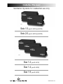
1
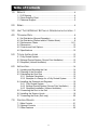
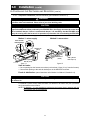
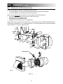
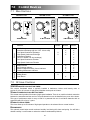
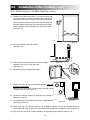
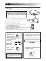
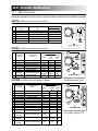
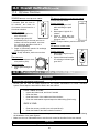
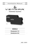
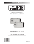
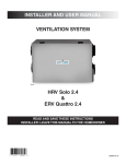
Installer Manual Ventilation Systems for residential use only VB0013 Solo 1.5 (part #: 43720 and 43725) Solo 2.0 (part #: 45720 and 45725) VB0012 Duo 1.2 (part #: 43710) Duo 1.4 (part #: 43700) Duo 1.9 (part #: 45700) 03309-04/01/12 Table of Contents 1.0 SERVICE..............................................................................................4 1.1 3-D Drawing ................................................................................4 1.2 Parts Ordering Chart....................................................................5 1.3 Technical Support ........................................................................5 2.0 SIZING ................................................................................................6 3.0 UNIT TYPE & DEFROST SETTING VS GEOGRAPHICAL LOCATION ..7 4.0 TECHNICAL DATA ................................................................................8 4.1 4.2 4.3 4.4 4.5 4.6 5.0 Air Distribution (Normal Operation)..............................................8 Air Distribution (Defrost and/or Filtration Mode) ..........................8 Performance Charts................................................................9-11 Dimensions ................................................................................12 Controls and Link Options..........................................................12 Specifications ............................................................................12 TYPICAL INSTALLATIONS ..................................................................13 5.1 Fully Ducted System ..................................................................13 5.2 Exhaust Ducted System (Source Point Ventilation) ..................13 5.3 Simplified (Volume Ventilation) ..................................................13 6.0 INSTALLATION ....................................................................................14 6.1 Locating and Mounting the Unit ................................................14 6.2 Planning of the Ductwork ..........................................................14 6.3 Calculating the Duct Size ..........................................................15 6.3.1 Example Calculation ........................................................15 6.3.2 Example of a Design for a Fully Ducted System ............15 6.4 Installing the Ductwork and Registers ......................................16 6.4.1 Fully Ducted System ........................................................16 6.4.2 Exhaust Ducted System (Source Point Ventilation) ........16 6.4.3 Simplified Installation (Volume Ventilation) ......................17 6.5 Connecting the Duct to the Unit ................................................18 6.6 Installing the Exterior Hoods ......................................................19 6.7 Connecting the Drain (Solo only) ..............................................20 7.0 CONTROL DEVICES ..........................................................................21 7.1 Main Controls ............................................................................21 7.2 Optional Controls ......................................................................21 7.3 Other Features ..........................................................................22 2 Table of Contents 8.0 INSTALLATION 8.1 8.2 8.3 8.4 8.5 9.0 10.0 OF THE (cont’d) CONTROLS ..................................................22 Dimensions and Specifications ................................................22 Installation of the Main Control ..........................................22-23 Installation of the Wireless Push button and Receiver ............24 Electrical Connection to Optional Controls ..............................25 Electrical Connection to the Furnace ......................................25 WIRING DIAGRAMS ....................................................................26-27 AIR FLOW BALANCING ................................................................28 11.0 OVERALL VERIFICATION ..................................................................29 11.1 Main Controls ..........................................................................29 11.2 Optional Controls ....................................................................30 12.0 MAINTENANCE / INSTRUCTIONS FOR USER ....................................30 13.0 TROUBLESHOOTING ....................................................................31-32 14.0 REFERENCES....................................................................................32 About this Manual This manual uses the following symbols to emphasize particular information: 0 ! WARNING Identifies an instruction which, if not followed, might cause serious personal injuries including possibility of death. CAUTION Denotes an instruction which, if not followed, may severely damage the unit and/or its components. NOTE: Indicates supplementary information needed to fully complete an instruction. 3 4 Unit shown in normal position. VL0007 3 2 1 25 4 6 5 22 7 8 21 1 12 11 3 1 10 20 0 1 13 18 1 19 8 9 17 14 1 18 8 15 1 16 1.1 24 4 23 3 17 1.0 Service 3-D DRAWING 1.0 Service (cont’d) 1.2 PARTS ORDERING CHART No Description 1 2 3 4 5 Double Collar Port #2 Damper #1 (kit) Damper Rod (kit) Electronic Board & spacers (kit) Thermistor (kit) 6 Door Latches & screws 7 8 9 10 11 12 13 14 15 19 Damper Actuator Assembly Basic Filter Blower Assembly Square Damper (kit) Top Wheel Motor Bottom Wheel Door Ass’y (including 15 to 17) Door Latches (keeper) & Screws Label Hinge Ass’y (kit) Pleated Optional Filter Charcoal Optional Filter Electronic Optional Filter Thermal Wheel 20 Recovery Core 21 22 23 Balancing Double Collar Port Balancing Damper Snap Bushing DP-750 & O-Ring Drain Connector (kit) Door Switch (SPST), E69 10A 16 17 18 24 25 SOLO 1.5 (A) 43720 (B) 43725 02257 12454 13037 13038 12895 00886 (2) 00601 (4) 13734 03308 12908 13033 02238 12109 02240 13346 00887 (2) 00601 (4) 03328 13036 03316 03315 03314 N/A (A) 03322 (B) 03311 02256 02253 03324 (2) 03310 (4) 03203 01825 SOLO 2.0 (A) 45720 (B) 45725 02257 12454 13037 13038 12895 00886 (2) 00601 (4) 13734 03308 12912 13033 02238 12157 02240 13346 00887 (2) 00601 (4) 03328 13036 03316 03315 03314 N/A (A) 03322 (B) 03311 02256 02253 03324 (2) 03310 (4) 03203 01825 DUO 1.2 43710 DUO 1.4 43700 DUO 1.9 45700 02257 12454 13037 13039 12895 00886 (2) 00601 (4) 13734 03308 12909 13033 02238 12109 02239 13346 00887 (2) 00601 (4) 03328 13036 03316 03315 03314 13045 02257 12454 13037 13039 12895 00886 (2) 00601 (4) 13734 03308 12909 13033 02239 12109 02239 13346 00887 (2) 00601 (4) 03328 13036 03316 03315 03314 13044 02257 12454 13037 13039 12895 00886 (2) 00601 (4) 13734 03308 12911 13033 02239 12157 02240 13346 00887 (2) 00601 (4) 03328 13036 03316 03315 03314 13045 N/A 02256 02253 03324 (2) 03310 (4) N/A 01825 N/A 02256 02253 03324 (2) 03310 (4) N/A 01825 N/A 02256 02253 03324 (2) 03310 (4) N/A 01825 Please take note that parts not listed are not available; those parts require assembly knowledge that only manufacturer can guarantee. TO ORDER PARTS: Contact your local distributor. 1.3 TECHNICAL SUPPORT (FOR ASSISTANCE) For assistance, call on weekdays, 8:30 AM to 5:00 PM (Eastern Standard Time). NOTE: Do not call this number for ordering parts. Canada & USA: 1-800-649-0372 (toll free) 5 2.0 Sizing These are the two most common methods used to evaluate the ventilation needs of a house: CSA F326 and Canadian Building Code: • High speed: 10 cfm per room 20 cfm for the master bedroom and the basement • Low speed: 40-60% of high speed ASHRAE Standard 62-2001: • 0.35 air change per hour Refer to ventilation code of your area to determine which method to use. Example: Bedroom #1 Main floor Bedroom #2 Living room Bathroom #3 Bathroom #2 Master Bedroom Bathroom #1 Second floor Laundry room Kitchen Dining room Bedroom #3 Family room 1320 ft2 1320 ft2 Basement Basement 1320 ft2 VH0021A CSA F326 ASHRAE Standard 62-1989 cfm) cfm) cfm) cfm) cfm) cfm) cfm) cfm) cfm) cfm) cfm) cfm) cfm) Kitchen Dining room Living room family room Master bedroom Bedroom #1 Bedroom #2 Bedroom #3 Bathroom #1 Bathroom #2 Bathroom #3 Laundry room Basement (10 (10 (10 (10 (20 (10 (10 (10 (10 (10 (10 (10 (20 Total 150 cfm Volume of basement Volume of main floor Volume of second floor 10560 ft3 10560 ft3 10560 ft3 Total volume 31680 ft3 x 0.35/h 11090 ft3/h ÷ 60 (min/h) Total 6 185 cfm 7 JUNEAU WHITEHORSE SALEM OLYMPIA HAY RIVER RENO BOISE PENTICTON ZONE C Solo or Duo (any models). “Extended defrost” not required (factory defrost strategy pre-set). ZONE B Solo is recommended but if a Duo unit is used, it has to be oversized (because of its high humidity transfer efficiency). Set “extended defrost” according to Section 9. PHOENIX SANTA FE DENVER ZONE C REGINA SASKATOON SALT LAKE CITY HELENA LETHBRIDGE CALGARY PRINCE ALBERT FORT MCMURRAY VN0001 AUSTIN DETROIT RALEIGH WASHINGTON COLUMBIA COLUMBUS HARRISBURG TORONTO OTTAWA NORTH BAY HARTFORD MONTR AL ST-JOHN MATANE BOSTON QUEBEC CHICOUTIMI VAL-DOR CHIBOUGAMAU GOOSE BAY HALIFAX CHARLOTTETOWN BATHURST GASP SEPT-ILES LABRADOR CITY ST JO and/or Important excess moisture problem and / or Excess moisture problem Indoor air quality problem VQ0013 SOLO DUO DUO SYMPTOM SOLUTION ZONE B & C SELECTION CHART (condensation) ATLANTA NASHVILLE INDIANAPOLIS BATON ROUGE SPRINGFIELD DES MOINES MADISON SUDBURY TIMMINS SAULT STE MARIE ZONE B ST. PAUL OKLAHOMA CITY TOPEKA BISMARCK WINNIPEG ZONE A NORTH AMERICA FORT SMITH EDMONTON GRANDE PRAIRIE KAMLOOPS JASPER SACRAMENTO VICTORIA Prince Rupert ZONE A Solo is recommended. Set :”extended defrost” according to Section 9. HORAGE YELLOWKNIFE 3.0 Unit Type & Defrost Setting vs Geographical Location 4.0 Technical Data 4.1 AIR DISTRIBUTION (NORMAL OPERATION) STALE AIR TO OUTSIDE VF0016 FRESH AIR FROM OUTSIDE FRESH AIR TO BUILDING SOLO STALE AIR TO OUTSIDE VF0017 STALE AIR FROM BUILDING 4.2 AIR DISTRIBUTION (DEFROST FRESH AIR FROM OUTSIDE AND/OR STALE AIR FROM BUILDING DUO FILTRATION MODE) FILTERED AIR TO BUILDING VF0018 SOLO FRESH AIR TO BUILDING STALE AIR FROM BUILDING VF0019 STALE AIR FROM BUILDING DUO FILTERED AIR TO BUILDING SOLO units Outside Temperature Celcius (˚C) Fahrenheit (˚F) Defrost Cycles Defrosting (min.) Operation time (min.) Extended Defrost Cycles Defrosting (min.) between each defrost cycle -5 -15 -27 23 5 -17 60 32 20 6 6 6 Operation time (min.) between each defrost cycle 10 10 10 30 20 15 DUO units Outside Temperature Celcius (˚C) Fahrenheit (˚F) Defrost Cycles Defrosting (min.) Operation time (min.) Extended Defrost Cycles Defrosting (min.) between each defrost cycle -5 -15 -27 23 5 -17 60 32 20 9 9 9 8 Operation time (min.) between each defrost cycle 10 10 10 30 20 15 4.0 (cont’d) PERFORMANCE CHARTS MODEL NUMBER: SOLO 1.5 External Static Pressure - Pascals (250 Pascals = 1” of water) 4.3 Technical Data Electrical requirements: 120 volts, 1.3 amps. Exhaust air transfer ratio: 0.01 VENTILATION PERFORMANCE External Static Pressure Pa in. w.g. Net Supply Air Flow L/s cfm Gross Air Flow Supply Exhaust L/s cfm L/s cfm 25 50 75 100 125 150 175 200 83 79 75 71 64 60 53 43 83 80 75 71 64 60 53 43 0.1 0.2 0.3 0.4 0.5 0.6 0.7 0.8 175 168 159 150 136 126 113 91 176 169 159 151 136 127 113 91 82 78 75 69 60 48 38 21 175 165 158 146 127 103 80 45 225 175 150 125 100 75 50 25 VG0010 HEATING 35 35 COOLING MODEL Net Air Flow L/s cfm 31 66 56 119 25 50 75 100 125 150 37 Sensible Recovery Efficiency % 69 60 Apparent Sensible Effectiveness % 81 70 Latent Recovery Moisture Transfer 114 62 80 0.08 78 -0.01 -0.01 Total Recovery Efficiency Not tested 95 95 NUMBER: SOLO 2.0 External Static Pressure - Pascals (250 Pascals = 1” of water) VENTILATION PERFORMANCE External Static Pressure Pa in. w.g. Net Supply Air Flow L/s cfm Gross Air Flow Supply Exhaust L/s cfm L/s cfm 25 50 75 100 125 150 175 110 104 98 89 84 71 64 112 105 100 91 85 72 65 234 219 208 189 177 151 136 0 Average Power watts 85 124 Electrical requirements: 120 volts, 2.1 amps. Exhaust air transfer ratio: 0.01 0.1 0.2 0.3 0.4 0.5 0.6 0.7 0 Gross Air Flow -L/s (0.47L/s = 1cfm) ENERGY PERFORMANCE Supply Temperature °C °F 0 32 0 32 0 32 -25 -13 -25 -13 Supply (l/s) Exhaust (l/s) 200 237 223 211 192 180 153 138 112 106 99 91 82 71 44 237 225 210 193 174 149 94 VG0011 225 Supply (l/s) Exhaust (l/s) 200 175 150 125 100 75 50 25 0 0 25 50 75 100 125 150 Gross Air Flow -L/s (0.47L/s = 1cfm) ENERGY PERFORMANCE HEATING COOLING Supply Temperature °C °F 0 32 0 32 -25 -13 -25 -13 35 35 Net Air Flow L/s cfm 56 119 86 182 37 78 Average Power watts 124 197 114 Sensible Recovery Efficiency % 60 53 62 Apparent Sensible Effectiveness % 70 62 80 Total Recovery Efficiency Not tested 95 95 9 Latent Recovery Moisture Transfer -0.01 -0.01 0.08 4.0 4.3 Technical Data PERFORMANCE CHARTS MODEL NUMBER: (cont’d) (CONT’D) DUO 1.2 External Static Pressure - Pascals (250 Pascals = 1” of water) Electrical requirements: 120 volts, 1.4 amps. Exhaust air transfer ratio: 0.01 VENTILATION PERFORMANCE External Static Pressure Pa in. w.g. Net Supply Air Flow L/s cfm Gross Air Flow Supply Exhaust L/s cfm L/s cfm 25 50 75 100 125 150 175 200 62 59 58 54 51 45 39 31 62 60 58 55 52 45 39 31 0.1 0.2 0.3 0.4 0.5 0.6 0.7 0.8 131 125 123 114 108 95 83 65 133 127 124 116 110 96 84 66 64 61 58 55 50 47 40 29 137 130 123 117 107 99 85 62 225 Supply (l/s) Exhaust (l/s) 200 175 150 125 100 75 50 25 0 0 25 50 75 100 125 150 Gross Air Flow -L/s (0.47L/s = 1cfm) VG0008 ENERGY PERFORMANCE COOLING MODEL Net Air Flow L/s cfm 32 68 56 119 51 35 35 31 55 95 95 NUMBER: Average Power watts 108 156 Sensible Recovery Efficiency % 77 71 Apparent Sensible Effectiveness % 87 81 Latent Recovery Moisture Transfer 108 189 66 82 0.69 66 117 103 151 DUO 1.4 Electrical requirements: 120 volts, 1.4 amps. Exhaust air transfer ratio: 0.02 VENTILATION PERFORMANCE External Static Pressure Pa in. w.g. Net Supply Air Flow L/s cfm Gross Air Flow Supply Exhaust L/s cfm L/s cfm 25 50 75 100 125 150 175 200 69 65 60 57 49 43 30 22 70 66 61 58 50 44 31 22 0.1 0.2 0.3 0.4 0.5 0.6 0.7 0.8 145 137 127 120 104 91 64 46 148 140 129 123 106 93 66 47 78 72 65 60 49 42 31 23 165 153 138 127 104 89 66 49 0.61 0.56 Total Recovery Efficiency 75 69 External Static Pressure - Pascals (250 Pascals = 1” of water) HEATING Supply Temperature °C °F 0 32 0 32 0 32 -25 -13 -25 -13 VG0009 225 Supply (l/s) Exhaust (l/s) 200 175 150 125 100 75 50 25 0 0 25 50 75 100 125 150 Gross Air Flow -L/s (0.47L/s = 1cfm) ENERGY PERFORMANCE HEATING COOLING Supply Temperature °C °F 0 32 0 32 0 32 -25 -13 -25 -13 Net Air Flow L/s cfm 32 68 47 100 57 121 29 61 35 35 31 57 95 95 66 121 Average Power watts 110 164 172 120 104 168 10 Sensible Recovery Efficiency % 70 65 64 64 Apparent Sensible Effectiveness % 80 74 72 79 Total Recovery Efficiency 69 61 Latent Recovery Moisture Transfer 0.79 0.67 0.60 0.65 4.3 Technical Data PERFORMANCE CHARTS MODEL NUMBER: (cont’d) (CONT’D) DUO 1.9 External Static Pressure - Pascals (250 Pascals = 1” of water) 4.0 Electrical requirements: 120 volts, 2.2 amps. Exhaust air transfer ratio: 0.01 VENTILATION PERFORMANCE External Static Pressure Pa in. w.g. Net Supply Air Flow L/s cfm Gross Air Flow Supply Exhaust L/s cfm L/s cfm 25 50 75 100 125 150 175 200 225 97 95 89 85 80 74 65 56 34 98 96 90 86 81 75 66 57 34 0.1 0.2 0.3 0.4 0.5 0.6 0.7 0.8 0.9 206 202 189 180 169 157 138 119 71 208 204 191 182 171 159 139 120 72 100 106 100 94 89 81 73 59 26 233 224 211 199 189 173 156 125 56 225 Supply (l/s) Exhaust (l/s) 200 175 150 125 100 75 50 25 0 0 VG0010 25 50 75 100 125 150 Gross Air Flow -L/s (0.47L/s = 1cfm) ENERGY PERFORMANCE HEATING COOLING Supply Temperature °C °F 0 32 0 32 0 32 -25 -13 -25 -13 Net Air Flow L/s cfm 56 119 84 178 51 35 35 55 95 95 Average Power watts 156 230 Sensible Recovery Efficiency % 71 65 Apparent Sensible Effectiveness % 81 72 Latent Recovery Moisture Transfer 108 189 66 82 0.69 117 151 11 Total Recovery Efficiency 69 0.56 0.46 4.0 4.4 Technical Data (cont’d) DIMENSIONS 6" (152 mm) 17 1/8" (435 mm) 30 1/4" (768 mm) 16 1/2" (419 mm) VK0029 4.5 CONTROLS AND LINK OPTIONS Main controls: • Venta • Supra • Ultima 4.6 Model Optional controls: • 20/40/60-minute push-button timer • 20-minute wireless push-button timer • 60-minute crank timer • Dehumidistat Link options: • Furnace interlock (used with forced air systems) • Interface for the Perfect Climate Comfort Center™ (Honeywell control, W8900) SPECIFICATIONS Solo 1.5 Solo 2.0 Duo 1.2 Duo 1.4 Duo 1.9 Weight 71 lbs (32 kg) 73 lbs (33 kg) 79 lbs (36 kg) 75 lbs (34 kg) 77 lbs (35 kg) Port Diameter 6” (152 mm) 6” (152 mm) 6” (152 mm) 6” (152 mm) 6” (152 mm) N/A Drain Diameter 1/2” (12 mm) 1/2” (12 mm) N/A N/A Installation Chains, springs and hooks (provided with the unit). Motor Speed High and low speed factory set (optional increased or decreased low speed). Electrical supply 120 V, 60 Hz 120 V, 60 Hz 120 V, 60 Hz 120 V, 60 Hz 120 V, 60 Hz Power 150 watts 240 watts 160 watts 160 watts 250 watts Consumption 12 5.0 Typical Installations *Installations may vary according to the model number and the position (normal or reverse) in which the unit is installed. There are three (3) common installation methods. 5.1 FULLY DUCTED SYSTEM (Primarily for homes with radiant hot water or electric baseboard heating. See figure 1.) Moist, stale air is exhausted from the high humidity areas in the home, such as bathrooms, kitchen and laundry room. Fresh air is supplied to bedrooms and principal living areas. The use of bathroom fans and a range hood is suggested to exhaust stale air. Homes with more than one level require at least one exhaust register at the highest level. See 6.4.1 for details VH0002 figure 1 5.2 EXHAUST DUCTED SYSTEM (SOURCE POINT VENTILATION) (For homes with forced air heating. See figure 2.) Moist, stale air is exhausted from the high humidity areas in the home, such as bathrooms, kitchen and laundry room. Fresh air is supplied to the cold air return or the supply duct of the furnace. The use of bathroom fans and a range hood is suggested to exhaust stale air. Homes with more than one level require at least one exhaust register at the highest level. NOTE: For this type of installation, it is not essential that the furnace blower runs when the unit is in operation, but we recommend it. 5.3 See 6.4.2 for details VH0006 figure 2 SIMPLIFIED (VOLUME VENTILATION) (For homes with forced air heating. See figure 3.) Fresh air and exhaust air flow through the furnace ducts which simplifies the installation. The use of bathroom fans and a range hood is suggested to exhaust stale air. NOTE: For this type of installation, the furnace blower should be running when the unit is in operation. See 6.4.3 for details VH0007 figure 3 13 6.0 Installation INSPECT THE CONTENTS • • • • OF THE BOX Inspect the exterior of the unit for shipping damage. Ensure that there is no damage to the door, door latches, door hinges, dampers, duct collars, cabinet, etc. Inspect the interior of the unit for damage. Ensure that the fan motor assembly, recovery module, insulation, dampers, damper actuator and condensation tray (Solo) are all intact. If the unit was damaged during shipping, contact your local distributor. (Claim must be made within 24 hours after delivery.) Use checklist included with the unit to ensure that no parts are missing. 6.1 LOCATING AND MOUNTING THE UNIT NOTE: Please note that the unit can be installed in either the “normal” or “reverse” (upside down) position. Choose an appropriate location for the unit: • Within an area of the house where the temperature is above 10°C / 50°F (basement, attic, furnace room, laundry room, etc.). • Away from living areas (dining room, living room, bedroom), if possible. • So as to provide easy access to the interior cabinet and to the control panel on the side of the unit. • Close to an exterior wall, so as to limit the length of the insulated flexible duct to and from the unit. • Close to a drain. If no drain is close by, use a pail to collect run-off. (Solo models only.) • Away from hot chimneys, electrical panel and other fire hazards. • Allow for a power source (standard outlet). VD0037 figure 4 Hang the unit with the 4 chains and springs provided (see figures 4 and 5). VD0038 figure 5 1/8" (3 mm) CAUTION Make sure the unit is level, with a 1/8’’ (3 mm) tilt backwards (see figure 6). level VD0039A figure 6 6.2 PLANNING OF THE DUCTWORK a) Follow the instructions in Section 6.3 next page to determine the appropriate duct diameters for your system. b) Keep it simple. Plan for a minimum number of bends and joints. Keep the length of insulated duct to a minimum. c) Do not use wall cavities as ducts. Do not use branch lines smaller than 4” (102 mm) Ø. d) Do not ventilate crawl spaces or cold rooms. Do not attempt to recover the exhaust air from a dryer or a range hood. This would cause clogging of the recovery module. Use sheet metal for the kitchen exhaust duct. e) Be sure to plan for at least one exhaust register on the highest lived-in level of the house if it has 2 floors or more. 14 6.0 Installation 6.3 (cont’d) CALCULATING THE DUCT SIZE Use the table below to ensure that the ducts you intend to install will be carrying air flows at or under the recommended values. Avoid installing ducts that will have to carry air flows near the maximum values and never install a duct if its air flow exceeds the maximum value. Duct Diameter 4”(102 5”(127 6”(152 7”(178 8”(203 mm) mm) mm) mm) mm) Recommended Air Flow 40 cfm 75 cfm 120 cfm 185 cfm 260 cfm 19 l/s 35 l/s 57 l/s 87 l/s 123 l/s end branches Maximum Air Flow 68 m3/h 127 m3/h 204 m3/h 314 m3/h 442 m3/h 60 cfm 28 l/s 110 cfm 52 l/s 180 cfm 85 l/s 270 cfm 127 l/s 380 cfm 179 l/s 5”ø 70 cfm 102 m3/h 187 m3/h 306 m3/h 459 m3/h 645 m3/h VI0003 NOTE: Examples 6.2.1 and 6.2.2 use imperial measures. The same calculation applies to metric measures. 6.3.1 main branch 6”ø 140 cfm figure 7 Example of calculation: Problem: My installation requires two exhaust registers (one for the kitchen, one for the bathroom). I will connect these registers to a main duct which will connect to the unit (high speed performance value of 140 cfm). What size of duct should I use for the main exhaust duct and for the two end branches leading to the registers? (See figure 7.) Solution: Simplified method. (For a more detailed method of calculating duct size refer to the ASHRAE or HRAI HANDBOOK). Main duct: Table above indicates a 6” Ø duct: recommended air flow: 120 cfm; maximum air flow: 180 cfm. The high speed air flow of 140 cfm is close enough to the recommended value (120) and far enough away from the maximum value (180). Therefore a 6”Ø duct or larger is an appropriate choice for the main exhaust duct. End branches: Each end branch will have to transport an air flow of 70 cfm (140 divided by 2). Table above indicates a 5”Ø duct: recommended air flow: 75 cfm; maximum air flow: 110 cfm. The high speed air flow of 70 cfm is close enough to the recommended value (75) and far enough away from the maximum value (110). Therefore a 5”Ø duct or larger is an appropriate choice for the 2 end branches. NOTE: A 4”Ø duct would have been too small because the maximum acceptable value for a 4”Ø duct is 60 cfm. 6.3.2 Example of a design for a fully ducted system for a unit having a high speed performance of 222 cfm (See figure 8). 4” 4” 5” 4” Ø 42 cfm 5” Ø 64 cfm 5” Ø 65 cfm 4” Ø 42 cfm 6” Ø 93 cfm 6” Ø 96 cfm 4” 6” 6” Ø 129 cfm 4” 6” Ø 84 cfm 6” 7” 7” 6” 6” 6” Ø 138 cfm 7” Ø 222 cfm VI0004 7” Ø 222 cfm figure 8 15 6.0 6.4 Installation (cont’d) INSTALLING THE DUCTWORK 0 ! AND REGISTERS WARNING Never install a stale air exhaust register in a room where there is a combustion device, such as a gas furnace, a gas water heater or a fireplace. 6.4.1 Fully Ducted System (as illustrated in Section 5.1) Stale air exhaust ductwork: • • • • Install registers in areas where contaminants are produced: kitchen, bathrooms, laundry room, etc. Install registers 6 to 12 inches (152 to 305 mm) from the ceiling on an interior wall OR install them in the ceiling. Install the kitchen register at least 4 feet (1.2 m) from the range. If possible, measure the velocity of the air flowing through the registers. If the velocity is higher than 400 ft/min. (122 m/min), then the register type is too small. Replace with a larger one. Fresh air distribution ductwork: • • • Install registers in bedrooms, dining room, living room and basement. Install registers either in the ceiling or high on the walls with air flow directed towards the ceiling. (The cooler air will then cross the upper part of the room, and mix with room air before descending to occupant level.) If a register must be floor installed, direct the air flow up the wall. 6.4.2 Exhaust Ducted System (Source Point Ventilation) (as illustrated in Section 5.2) Stale air exhaust ductwork: (same as for Fully Ducted System, described on point 6.4.1) Fresh air distribution: ! WARNING When performing duct connection to the furnace, installation must be done in accordance with all applicable codes and standards. Please refer to your local building code. CAUTION When performing duct connection to the furnace supply duct, this duct must be sized to support the additional airflow produced by the ERV/HRV. Also, use a steel duct with a backdraft damper. If there is no backdraft damper, it is mandatory that the ERV/HRV must always be running when the furnace is in operation to prevent the risk of overheating the ERV/HRV. There are two methods for connecting the unit to the furnace: Method 1: supply side connection Steel duct with backdraft damper • Cut an opening into the furnace supply duct at least 18 inches (0.5 m) from the furnace. • Connect this opening to the fresh air distribution port of the HRV/ERV (use steel duct, see figure 9). • Make sure that the HRV/ERV duct forms an elbow inside the furnace ductwork. • If desired, interlock (synchronize) the furnace blower operation with the HRV/ERV operation. (See Section 8.5). minimum 18” (0.5 m) Method 2: return side connection • Cut an opening into the furnace return duct not less than 10 feet (3.1m) from the furnace (A+B). • Connect this opening to the fresh air distribution port of the HRV/ERV (see figure 10). NOTE:For Method 2, it is not essential that the furnace blower runs when the unit is in operation, but we recommend it. If desired, synchronize the furnace blower operation with the HRV/ERV operation (see Section 8.5). 16 figure 9 A B VD0108 A+B = not less than 10’ (3.1 m) figure 10 6.0 Installation (cont’d) 6.4 INSTALLING THE DUCTWORK AND REGISTERS (CONT’D) 6.4.3 Simplified installation (Volume Ventilation) (as illustrated in Section 5.3) 0 ! WARNING When performing duct connection to the furnace, installation must be done in accordance with all applicable codes and standards. Please refer to your local building code. CAUTION When performing duct connection to the furnace ducts (Method 1), these ducts must be sized to support the additional airflow produced by the ERV/HRV. Also, the supply duct must be a steel duct with a backdraft damper. If there is no backdraft damper, it is mandatory that the ERV/HRV must always be running when the furnace is in operation to prevent the risk of overheating the ERV/HRV. There are two methods (figures 11 and 12) for connecting the unit to the furnace: Method 1: return-supply Method 2: return-return Steel duct with backdraft damper minimum 18” (0.5 m) A B A minimum 3’ (0.9 m) B VD0159 A+B = not less than 10’ (3.1 m) A+B = not less than 10’ (3.1 m) figure 12 figure 11 Stale air intake: • Cut an opening into the furnace return duct (not less than 10 feet (3.1 m) from the furnace). • Connect this opening to the stale air intake port on the HRV/ERV as shown. Fresh air distribution: (same instructions as for Method 1 or Method 2, Section 6.4.2). CAUTION If using Method 2, make sure the furnace blower operation is synchronized with the unit operation! See Section 8.5. For Method 2 (return-return) make sure there is a distance of at least 3 feet (0.9 m) between the 2 connections to the furnace. NOTE: For Method 1, it is not essential to synchronize the furnace blower operation with the unit operation, but we recommend it. 17 6.0 6.5 Installation (cont’d) CONNECTING THE DUCT TO THE UNIT Insulated flexible duct Use the following procedure for connecting the insulated flexible duct to the ports on the unit (exhaust to outside and fresh air from outside). a) Pull back the insulation to expose the flexible duct. b) Connect the interior flexible duct to the port using a duct tie. c) Carefully seal the connection with duct tape. d) Pull the insulation over the joint and tuck it between the inner and outer rings of the double collar. e) Pull the vapor barrier over the insulation and over the outer ring of the double collar. f) Apply duct tape to the joint making an airtight seal. Avoid compressing the insulation when you pull the tape tightly around the joint. Compressed insulation loses its R value and causes water dripping due to condensation on the exterior surface of the duct. CAUTION Make sure that the vapor barrier on the insulated ducts does not tear during installation to avoid condensation within the duct. a) b) VJ0001 c) VJ0002 d), e) VJ0004 VJ0003 f) VJ0005 Rigid duct: Use duct tape to connect the rigid ducts to the ports. CAUTION Do not use screws to connect rigid ducts to the ports. Make sure that the 2 balancing dampers are left in a fully open position before connecting the ducts to these ports (fresh air distribution port and stale air exhaust port as shown on figure 13). VJ0007 figure 13 18 6.0 6.6 Installation (cont’d) INSTALLING THE EXTERIOR HOODS Choose an appropriate location for installing the exterior hoods: • a minimum distance of 6 feet (1.8 m) between the hoods to avoid cross-contamination • a minimum distance of 18 inches (457 mm) from the ground Make sure the intake hood is at least 6 feet (1.8 m) away from any of the following: • dryer exhaust, high efficiency furnace vent, central vacuum vent • gas meter exhaust, gas barbecue-grill • any exhaust from a combustion source • garbage bin and any other source of contamination Refer to figure 14 for connecting the insulated duct to the hoods. Place the “FRESH AIR INTAKE” sticker, provided in the installation kit, on corresponding hood. An “Anti-Gust Intake Hood” should be installed in regions where a lot of snow is expected to fall. 6”Ø (152 mm) Exhaust hood 18” (457 mm) Intake hood 6’ (1.8 m) 18” (457 mm) Optional duct location Tape and duct tie VD0028 figure 14 19 6’ (1.8 m) 18” (457 mm) 6.0 6.7 Installation (cont’d) CONNECTING THE DRAIN (SOLO ONLY) Inside view 1 VO0010 VO0008 2 In order to keep the drain pan intact, hand tighten the 2 plastic drain fittings to the unit using the gaskets, washers and nuts as shown. To install the drain fittings, punch the 2 knock-out sections located at the bottom of the unit. 12"(305 mm) VO0004 3 VO0005 Cut 2 sections of plastic tubing, about 12” (305 mm) long and attach them to each drain fitting. 4 Join the 2 short sections to the “T” junction and main tube as shown. Tie-wrap Inside view To drain VO0011 VO0012 5 6 From the inside, install 2 snap bushings on top of the unit. Do not punch the 2 knock-out sections. Make a water trap loop in the tube to prevent the unit from drawing unpleasant odors from the drain source. Make sure this loop is situated BELOW the “T” as shown. This will prevent water from being drawn back up into the unit in case of negative pressure. Run the tube to the floor drain or to an alternative drain pipe or pail. Be sure there is a slight slope for the run-off. 20 7.0 7.1 Control Devices MAIN CONTROLS VENTA model SWITCHES INDICATORS MODELS MODELS 7.2 ULTIMA model SUPRA model Off Position Intermittent Exchange (40 min./ OFF -20 min./ON) Low Speed Continuous Exchange High Speed Continuous Exchange Intermittent Filtration (40 min./ filtration -20 min./exchange) Low Speed Continuous Filtration High Speed Continuous Filtration VENTA SUPRA X X X X X X X X X X X X X X Mode Indicator Air Exchange Indicator Maximum Speed Humidity Control Indicator Flashing Maintenance Indicator Sliding Button ULTIMA X X X X X X X X X X X Push Button OPTIONAL CONTROLS PUSH-BUTTON TIMER: This remote illuminated switch is typically installed in bathrooms, kitchen and laundry room to provide 20, 40 or 60 minutes of high speed ventilation at the push of a button. 20/40/60-MINUTE 20-MINUTE WIRELESS PUSH-BUTTON TIMER: This remote control provides 20 minutes of high speed ventilation. There is no need for electrical connection between the transmitter and the receiver. The push-button timer can be installed in any room in the house. This type of push-button switch is easy to intall. It is powered from two 3-volt lithium batteries with an expected battery life of up to 3 years. 60-MINUTE CRANK TIMER: This timer allows up to 60 minutes of high speed operation to be selected from a remote location. DEHUMIDISTAT: This optional control helps control maximum humidity level during fall, winter and spring. You will find a relative humidity % scale meant to reduce the window condensation problems. 21 7.0 7.3 Control Devices (cont’d) OTHER FEATURES FURNACE INTERLOCK (for forced air heating system) The furnace fan can be interlocked so that it will run simultaneously with the ventilation system to ensure proper distribution of fresh air throughout the house. The Perfect Climate Comfort Center™ With the help of an interface, the operation of your ventilation system can be controlled by The Perfect Climate Comfort Center™ (Honeywell control, W8900). PERMANENT MEMORY Our electronic controls have a default memory feature in the event of a power outage. Even the date of the last service reminder is maintained as a convenience to the homeowner. CONTROL UPGRADES All controls can be used on any unit, so a Venta control can be upgraded to a Supra or an Ultima in the future. 8.0 8.1 Installation of the Controls DIMENSIONS AND SPECIFICATIONS (MAIN CONTROLS) 13/8" (35 mm) Voltage: 12 volts DC Dimensions: 5” x 5” x 1 3/8” 5" (127 mm) (127 mm x 127 mm x 35 mm) 5" (127 mm) VC0016 FRONT VIEW 8.2 SIDE VIEW INSTALLATION OF THE MAIN CONTROL (VENTA, SUPRA & ULTIMA ) CAUTION Never install more than one main control per unit. INSTRUCTIONS: 1- Determine the location of the control. The wall control must be installed in a central location on the main floor. Typical locations for these controls are kitchen, main hallways and family room. 2- Remove the button(s) and the cover plate of the control. VC0026 Supra or Ultima 22 Venta 8.0 8.2 Installation of the Controls INSTALLATION OF THE MAIN CONTROL (cont’d) (CONT’D) 3- Install the wall control 60 inches (1.5 m) from the floor and leave a free space of at least 2 inches (5 cm) to the right of the control to allow user to slide out the control instructions. 2" (5 cm) Use the template provided in the control box to position the wire hole and the screw holes. Use the screws and the plastic anchors provided in the installation kit to secure the control. (See figure 15) 60"" (1.5 m) VD0025 figure 15 Y 5- Make sure the instruction pull-out is in the occupant’s language. If not, turn it to the other side. (See figure 17) R GB VD0026 4- Connect the wires to the main control. (See figure 16) figure 16 6- Re-install the cover plate and the buttons. figure 17 VC0061 7- Connect the wires to their corresponding position inside the electrical compartment. Make sure the connections of the unit and of the wall control correspond exactly. (See figure 18) 8- Connect the optional controls (if applicable) by referring to Sections 8.3 and 8.4. 9- Do the appropriate connection to the furnace (if applicable) by referring to Section 8.5. VE0084 figure 18 F F I OC OL Y R G B 10- NOTE: If you are in a cold region (zone A or B, as defined in Section 3.0), set up “extended defrost” by removing jumper JU1F on the main circuit board inside the electrical compartment (see Section 9.0). 11- Plug in the unit and do the “overall verification” of the system as described in Section 11.0. 23 8.0 8.3 Installation of the Controls INSTALLATION (cont’d) OF THE WIRELESS PUSH BUTTON AND RECEIVER INSTRUCTIONS: 1- Determine the location of the receiver illustrated in figure 19. Important: • Mount receiver as high as possible for best radio range. • Don’t mount the receiver or push button directly on metal, concrete or near metal studs. This can decrease radio range by shielding the signal. • Keep the receiver away from motors, fans and other electrical devices that may cause interference and reduce radio range. VC0062 figure 19 234567- Use screws to attach the mounting bracket (see figure 20). Snap the receiver onto the bracket (see figure 20). Pull the antenna straight. VC0063 Connect the wires referring to Section 8.4. figure 20 Remove the plastic tab on the push button. Program the memory of the receiver for each push button (see “Programming Memory” below). 8- Determine the location of the push button. 9- Use the screws to attach the push button mounting bracket (see figure 21). 10- Snap the push button onto bracket. figure 21 11- Do the “overall verification” as described in Section 11.2. VC0064 PROGRAMMING CHECKING MEMORY 1. Press and release the program button. 2. Program indicator will light for 3 seconds if there is room in memory for another push button (32 push VC0065 buttons max.). 1. Press and hold the program button for about two seconds until indicator lights, then release (see drawing below). 2. Count the number of indicator blinks. This is the total number of push buttons programmed. NOTE: Do not continue to press button or memory will be erased. NOTE: The switch on the back of each push button must be set at “INSTANT” position. ERASING Within 3 seconds, press the push button. Indicator will flash as signal is received. 4. VC0067 Repeat the above three steps for each additional push button. Press the program button and continue to hold it through the count of the push buttons. 2. Continue to hold the button after the count until the indicator blinks one more time (about five seconds after the count). 3. All push buttons programmed into memory will be erased. NOTE: The receiver can memorize each push button more than once. To prevent duplication of entries, program each push button into receiver only once. VC0065 24 MEMORY 1. VC0066 3. MEMORY 8.0 8.4 Installation of the Controls (con’d) ELECTRICAL CONNECTION TO OPTIONAL CONTROLS RECEIVER + - N.O. COM N.C. WIRELESS PUSH BUTTONS MAIN PC BOARD J1 B G R Y OL OC I 9 8 7 6 5 4 3 2 1 J3 1 4 2 5 8 3 6 9 7 HUMIDITY PUSH-BUTTON SWITCHES CONTROL OR (10 SWITCHES MAXIMUM) CRANK TIMER VE0085A 8.5 ELECTRICAL CONNECTION TO THE FURNACE 0 ! WARNING Never connect a 120-volt AC circuit to the terminals of the furnace interlock (standard wiring). Only use the low voltage class 2 circuit of the furnace blower control. For a furnace connected to cooling system: On some older thermostats, energizing the “R” and “G” terminals at the furnace has the effect of energizing “Y” at the thermostat and thereby turning on the cooling system. If you identify this type of thermostat, you must use the “alternate furnace interlock wiring”. An additional control relay will then have to be installed. Standard furnace interlock wiring W G Y Unit Control Module 9-PIN AMP PLUG THERMOSTAT TERMINALS W 4 WIRES HRV CONTROL CONNECTOR J3 TWO WIRES heating only 9 8 7 6 5 4 3 2 1 FOUR WIRES R Alternate furnace interlock wiring F F I OC OL Y R G B Y THERMOSTAT TERMINAL J1 heating only wiring nuts W R RR G G 4 77 2 5 8 3 6 9 BROWN GREEN NC BLUE YY Y 1 GRAY RED C C VE0010A G 2 WIRES W FURNACE 24-VOLT TERMINAL BLOCK R NO COM *FURNACE INTERLOCK RELAY FURNACE 24-VOLT TERMINAL BLOCK TWO WIRES 2 WIRES COOLING SYSTEM VE0009A 25 *FURNACE INTERLOCK RELAY, PART # 12658 COOLING SYSTEM 26 BK O BL NO BK BL BN G GY DOOR INTERLOCK SWITCH S1 COM BL BL BL G BLACK BLUE BROWN GREEN GREY LINE BK W G NEMA-15P 5-15 PLUG W1 120V 60 Hz DAMPER MOTOR M2 MAIN EARTHING POINT G 3 2 1 NEUTRAL BL BL G X2 C1 6- The furnace fan circuit must be class 2 circuit only. 5- The field wiring must comply with applicable codes, ordonnances and regulations. 4- Use the factory supplied protective tubing. 3- If any of the original wire, as supplied, must be replaced, use the same or equivalent wire. COLOR CODE NC O R W Y NO CONNECTION ORANGE RED WHITE YELLOW LOW VOLTAGE AND FIELD WIRE BK R LINE VOLTAGE NOTES W GY M1 X1 GY 12 GY NEUTRAL O 3 O HIGH G G BN LOW NC R MEDIUM BN R BL (NOTE 2) FAN MOTOR FURNACE BLOWER INTERLOCK NOTES 5, 6 OPTIONAL OVERRIDE SWITCH NOTE 5 OVERRIDE SWITCH OPTIONAL OVERRIDE LED R BK Y NOTES 1, 5 WALL CONTROL WALL CONTROL WALL CONTROL WALL CONTROL BK G R Y 2- The factory set wiring for blower speed selection is high and low. Medium speed can be selected instead of low speed. Disconnect the RED wire from the motor RED tap and connect it to the motor BLUE tap. VE0017A ELECTRONIC ASSEMBLY T1 8 7 Connection 120V 60Hz OUT OUT IN IN JU1B Logic JU1A OUT OUT JU1C JUMPERS TABLE VE0018A FROM MAIN JU 1 J1 4 J1 6 J3 1 K5 RELAY K2 RELAY A1 MODEL OUT IN IN JU1E 2 1 OUT OUT JU1G TYPE K2 0 0 1 0 1 1 0 LOW M1 M2 FAN MOTOR J1 8 J1 1 DEFROST TIME DAMPER MOTOR HIGH MED NEUTRA J1 2 10/30 6/60 K5 1 0 0 1 1 1 1 10/20 6/32 10/15 6/20 DEFROST/VENTILATION MINUTES 23°F 5°F -22°F -5°C -15°C -27°C NC RELAY K4 0 1 1 1 1 1 0 43720, 45720 43725, 45725 EXTENDED DEFROST ALL TYPES FUNCTION TABLE MODE K1 Intermittent 0 Exchange Low 1 Exchange High 1 Circulation Low 1 Circulation High 1 Defrost Cycle 1 Off 0 0 = Relay coil is de-energized 1 = Relay coil is energized OUT IN JU1F A B C D E F G OUT J1 9 FURNACE BLOWER INTERLOCK CLASS 2 CIRCUIT ONLY J3 2 ELECTRONIC ASSEMBLY K1 RELAY K4 RELAY J1 3 JU1D S1 .. .. .. .. .. .. .. 1- Controls available. See Section 8.0 (Low voltage only, 12VDC) R1 A1 JU1 J4 J1 9 ABCDEFG 6 5 4 3 2 DEFROST TEMPERATURE SENSOR 2 1 1 2 3 1 4 ! 6 F F I OCOLY R G B 7 NOTE 4 J3 Models: SOLO 1.5 and 2.0 Risk of electrical shocks. Before performing any maintenance or servicing, always disconnect the unit from its power source. 0 9 9.0 Wiring Diagrams WARNING VE0019A ELECTRONIC ASSEMBLY T1 BL BK 27 4 3 2 1 JU1 X3 W GY R2 BK O NOTES BK V BN BN CAPACITOR LINE NEUTRAL GROUND DRIVING MOTOR RT1 G W R BK V 4 3 2 1 X3 3 2 1 R2/R3 BK DRIVING MOTOR CAPACITOR 1.7 uF, 250 VAC 1 uF, 330 VAC 1 uF, 250 VAC DRIVING MOTOR RESISTOR 300 Ohms, 7W 400 Ohms, 10W 800 Ohms, 8W Bodine Eastern Air Devices Warner Electric DRIVING MOTOR 6- Furnace fan circuit must be class 2 circuit only. BK BL BN G GY 5- Field wiring must comply with applicable codes, ordonnances and regulations. 4- Use factory supplied protective tubing. COLOR CODE BLACK NC BLUE O BROWN R GREEN-YELLOW V GREY W Y 3- If any of the original wire, as supplied, must be replaced, use the same or equivalent wire. CAPACITOR LINE NEUTRAL GROUND DRIVING MOTOR RT1 G W R BK M3 120V 60 Hz NO CONNECTION ORANGE RED VIOLET WHITE YELLOW LOW VOLTAGE AND FIELD WIRE LINE VOLTAGE V V BYPASS THERMAL ACTUATOR C2 W1 NEMA-15P 5-15 PLUG 2- Factory set wiring for blower speed selection is high and medium. Low speed can be selected instead of medium speed. Disconnect the RED wire from the motor BLUE tap and connect it to the motor RED tap. X3 LINE W G DAMPER MOTOR M2 M1 FAN MOTOR GY NEUTRAL O HIGH G BN R C1 LOW MEDIUM BN BL Y Y G NEUTRAL X2 DRIVING MOTOR RT1 V V BYPASS THERMAL ACTUATOR C2 L CAPACITOR LINE OW THERMAL WHE ASSEMBLY NEUTRAL GROUND M3 E SB G W R BK XE O EB R2 SE X1 GY 21 O 3 G NC R 4 3 2 1 BL BL G BN Y V V BYPASS THERMAL ACTUATOR C2 NO DOOR INTERLOCK SWITCH S1 M3 COM MAIN EARTHING POINT R Y G OVERRIDE SWITCH OVERRIDE SWITCH NOTE 5 OPTIONAL OVERRIDE LED R BK Y FURNACE BLOWER NOTE 6 OPTIONAL INTERLOCK WALL CONTROL WALL CONTROL NOTE 5 WALL CONTROL WALL CONTROL BK G R Y K1 RELAY K4 RELAY J1 3 IN JU1B IN 1 K1&K4 0 1 1 1 1 OUT JU1C OUT Off 0 0 = Relay coil is de-energized 1 = Relay coil is energized Defrost Cycle FUNCTION TABLE MODE Intermittent Continuous Low Continuous High Circulation Low Circulation High IN S1 JUMPERS TABLE JU1A IN VE0020A FROM MAIN 120V 60Hz J2 3 J1 7 K5 RELAY K2 RELAY J3 2 J3 1 JU 1 J2 2 J2 1 J9 1 2 1 0 1 K2 0 0 1 0 1 0 0 K3 0 1 1 0 0 IN JU1E IN RELAY OUT JU1D OUT OUT 1 1 K5 1 0 0 1 1 JU1F IN A B C D E F G NC LOW RT1 MEDIUM HIGH M1 FAN MOTOR EXTENDED DEFROST 43700, 45700, 43710 MODEL DAMPER M2 MOTOR DRIVING MOTOR M3 BYPASS THERMAL ACTUATOR -5°C -15°C -27°C STANDARD 9/60 min 9/32 min 9/20 min J1 5 J1 8 J1 1 NEUTRAL J1 2 EXTENDED 10/30 min 10/20 min 10/15 min K5 active only (-15°C<T<+10°C) DEFROST OUT JU1G OUT FURNACE BLOWER INTERLOCK CLASS 2 CIRCUIT ONLY K3 RELAY J1 4 J1 6 ELECTRONIC ASSEMBLY A1 .. .. .. .. .. .. .. 1- Controls available. See Section 8.0. (Low voltage only 12VDC) R1 DEFROST TEMPERATURE SENSOR 8 7 6 5 4 3 2 A1 NOTE 4 9 ABCDEFG 3 1 2 J4 J2 2 1 1 2 3 J1 1 4 6 F F I OCOL Y R G B 7 9 Connection ! BODINE OR EASTERN AIR DEVICES J3 Models: DUO 1.2, 1.4 and 1.9 Wiring Diagrams 30 30 9.0 (cont’d) Risk of electrical shocks. Before performing any maintenance or servicing, always disconnect the unit from its power source. WARNING Logic 10.0 Air Flow Balancing WHAT YOU NEED TO BALANCE THE UNIT • • A magnehelic gauge capable of measuring 0 to 0.5 inch of water (0 to 125 Pa) and 2 plastic tubes. The balancing chart provided with the unit. VP0009 PRELIMINARY STAGES TO BALANCE THE UNIT • • • • Seal all the unit ductwork with tape. Close all windows and doors. Turn off all exhaust devices such as range hood, dryer and bathroom fans. Make sure the balancing dampers are fully open. Make sure all filters are clean (if it is not the first time you balance the unit). VD0051 SOLO BALANCING PROCEDURE 1. Set the unit to high speed: Make sure that the furnace blower is ON if the installation is in any way connected to the ductwork of the cold air return. If not, leave furnace blower OFF. If the outside temperature is below 0°C / 32°F, make sure the unit is not running in defrost while balancing. (By waiting 10 minutes after plugging the unit in, you are assured that the unit is not in a defrost cycle.) Disconnect the wire of the bypass damper (Duo only). Fresh air flow VP0010 Exhaust air flow 2. Place the magnehelic gauge on a level surface and adjust it to zero. DUO 3. Connect tubing from gauge to EXHAUST air flow pressure taps (see diagram). Be sure to connect the tubes to their appropriate high/low fittings. If the gauge drops below zero, reverse the tubing connections. NOTE: It is suggested to start with the exhaust air flow reading because the exhaust has typically more restriction than the fresh air, especially in cases of fully ducted installations or source point ventilation. Place the magnehelic gauge upright and level. Record equivalent AIR FLOW of the reading according to the balancing chart. Exhaust air flow VP0011 Fresh air flow 4. Move tubing to FRESH air flow pressure taps (see diagram). Adjust the fresh air balancing damper until the fresh air flow is approximately the same as the EXHAUST air flow. If fresh air flow is less than exhaust air flow, then go back and adjust the exhaust balancing damper to equal the fresh air flow. VE0021 5. Secure both dampers in place with tape or with a fastening screw. NOTE: Always unplug bypass wire while balancing a Duo. 6. Write the required air flow information on a label and stick it near the unit for future reference (date, maximum speed air flows, your name, phone number and business address). Connect the wire of the bypass damper (Duo only). NOTE: The unit is considered balanced even if there is a difference of +/- 10 cfm or +/- 5 l/s or 17 m3/h between the two air flows. VD0052 28 11.0 Overall Verification 11.1 MAIN CONTROLS This procedure allows the installer to verify that all modes of operation are fully functional. During the verification of a main control, make sure that all optional remote controls are inactive. VENTA 1 2 3 4 5 6 (6 different control scenarios to be tested) Set the slider switch to off off min. min. max. max. SUPRA Set dehumidistat dial to maximum counterclockwise maximum clockwise maximum counterclockwise maximum clockwise maximum counterclockwise maximum clockwise Results expected fan speed / damper motor off / closed motor off / closed low speed / open high speed / open high speed / open high speed / open (8 different control scenarios to be tested) A Set air supply control to 1 2 3 4 5 6 7 8 off off min. min. max. max. intermittent intermittent ULTIMA Set dehumidistat dial to maximum counterclockwise maximum clockwise maximum counterclockwise maximum clockwise maximum counterclockwise maximum clockwise maximum counterclockwise maximum clockwise Results expected Fan Exchange Max speed speed indicator indicator (A) (B) off *off off off *off off low on off high on on high on off high on on off 40 min *off 40 min off low 20 min on 20 min off high on on *The dampers are closed when the exchange indicator is off. (14 different control scenarios to be tested) Set air supply control to 1 off 2 off 3 min. (green light) 4 min. (green light) 5 min. (red light) 6 min. (red light) 7 max. (green light) 8 max. (green light) 9 max. (red light) 10 max. (red light) intermittent 11 (green light) intermittent 12 (green light) intermittent 13 (red light) intermittent 14 (red light) Set dehumidistat dial to maximum counterclockwise maximum clockwise maximum counterclockwise maximum clockwise maximum counterclockwise maximum clockwise maximum counterclockwise maximum clockwise maximum counterclockwise maximum clockwise maximum counterclockwise maximum counterclockwise maximum counterclockwise maximum counterclockwise Results expected Exchange Max speed indicator indicator (A) (B) off *off off off *off off low on off high on on low *off off high on on high on off high on on high *off off high on on off / 40 min. *off / 40 min. off low / 20 min. on / 20 min. off Fan speed high on low / 20 min. on / 20 min. high / 40 min .*off / 40 min. high on 29 B on off off on A B *The dampers are closed when the exchange indicator is off. 11.0 Overall Verification 11.2 (cont’d) OPTIONAL CONTROLS First, turn OFF the main control device before checking the remote optional controls. 20/40/60-MINUTE 20-MINUTE WIRELESS PUSH-BUTTON TIMER: PUSH-BUTTON TIMER: Activate the push button. Activate the push button. Within 2 seconds, push one time for 20 minutes, two times for 40 minutes or three times for a 60-minute activation. Results expected: 1. Indicator light goes “ON” while activating the push button. 2. Motor speed: high for 20 minutes. 3. Supra or Ultima wall controls: Air exchange indicator light goes “ON”. NOTE: To stop activation, push one more time. 20 min. 40 min. 60 min. Results expected: 1. Motor speed: high for 20, 40 or 60 minutes. VC0007 2. Indicator light goes “ON” and flashes every 5 seconds (one time to indicate a 20-minute operation, two times for a 40-minute, and three times for a 60-minute operation). 3. Supra or Ultima wall controls: Air exchange indicator light goes “ON”. NOTE: To stop activation, push one more time. VC0006 60-MINUTE CRANK TIMER: Activate the timer. Results expected: 1. Motor speed: high for up to 60 minutes. 2. Supra or Ultima wall controls: Air exchange indicator light goes “ON”. DEHUMIDISTAT: Turn dial to the maximum clockwise position (20%). Result expected: 1. Motor speed changes to high. TURN PAST 20 OFF 10 20 30 60 40 50 VC0017 12.0 Maintenance / Instructions for User 0 ! WARNING Risk of electrical shocks. Before performing any maintenance or servicing, always disconnect the unit from its power source. • Review with the user the steps required for the regular maintenance of her/his ventilation system. These steps are described in detail in the user manual: FOUR TIMES A YEAR: • • • • Inspect the intake hood, and clean if needed. Clean the filters. Clean the interior of the cabinet and clean the door. Clean the condensation tray and inspect the drain tubing (SOLO only). ONCE A YEAR: • • Clean the recovery module (core or thermal wheel). Clean the blades of the blower wheels if needed. • Warn the user of the necessity to rebalance the system following a major house renovation or following the installation of any extra registers. • Make sure the user understands how to use the main control as described in the user manual. CAUTION Do not oil the motor. It is already permanently lubricated. 30 13.0 Troubleshooting NOTE: Be sure to unplug and inspect the unit before proceeding with these steps. Start-up troubleshooting: Problems Possible causes You should try this 1. Unit doesn't work. • The circuit board may be defective. • Unplug the unit. Disconnect the main control and the optional(s) contol(s) (If need be). Jump B and G terminals. Plug the unit. If the motor runs on high speed and the damper opens, the circuit board is not defective. B G VE0082 . 2. The damper actuator does not work. 3. The wall control does not work OR the indicators flash. 4. The dehumidistat does not work OR the 20/40/60-min. push-button timer does not work OR its indicator light does not stay on. • The 9-pin connector may have a loose connection. • Unplug the unit and check to make sure all the crimp connections are secured. Check the damper actuator connections as well. • The damper actuator may be defective. • Feed 120 V directly to the damper actuator. If the problem persists, replace the damper actuator. • The circuit board may be defective. • Replace the circuit board if the problem is not solved by the above. • Erratic operation of the control every 8 seconds. • Unplug the unit. Wait 30 seconds. Plug it back in. • The wires may be in reverse position. • Ensure that the color coded wires have been connected to their appropriate places. • The wires may be broken. • Inspect every wire and replace any that are damaged. • There may be a short-circuit. • With the help of a multimeter, check for continuity. • The wire in the wall OR the wall control may be defective. • Jump “B” and “G” (BLACK and GREEN). If unit switches to high speed, remove the wall control and test it right beside the unit using another shorter wire. If the wall control works there, change the wire. If it doesn’t, change the wall control. • The circuit board may be defective. • If the unit does not switch to high speed, replace the circuit board. • The dehumidistat or push button may be defective. • Jump the OL and OC terminals. If the unit switches to high speed, remove the dehumidistat or push button and test it right beside the unit using another shorter wire. If it works there, change the wire. If it doesn’t, change the dehumidistat or the push button. OL OC VE0081 31 13.0 Troubleshooting Problems (cont’d) Possible causes You should try this 5. 20-min. wireless push • Plastic tab on batteries has not • Remove the tab, program memory of receiver and try button timer doesn’t work. been removed from push button. again (see Section 8.3). • Poor location for push button and/or receiver. • Use 1/4” to 1/2” wood shims to move off the surface or try different locations. • Light indicator flashes while activating the push button. • Low batteries. Open push button casing and change batteries. (Refer to user manual.) • Push button batteries are dead. • Open push button casing and change batteries. (Refer to user manual.) • Push button not properly • Re-program the memory of the receiver (refer to programmed in receiver or the Section 8.3). switch on the back of the push button is not at “instant” position. 6. The defrost cycle does not work (the fresh air duct is frozen OR the fresh air distributed is very cold OR the “AIR EXCHANGE” light flashes). • Receiver not properly wired. • Ensure that the wires have been connected to their appropriate places (see Section 8.4). • The wires may be broken. • Inspect every wire and replace any that are damaged. • There may be a short-circuit. • With the help of a multimeter, check for continuity. • Ice deposits may be hindering the damper operation. • Remove the ice. •The damper rod or the port damper itself may be broken. • Inspect these parts and replace if necessary. • The damper actuator may be defective. • Plug in the unit and select “MIN” or “MAX”. Press the door switch and see if the port damper opens. If it doesn’t open, feed 120V directly to the damper actuator. If the port damper still doesn’t open, replace the damper actuator. • The circuit board may be defective. • Unplug the unit. Unplug the defrost sensor wire (see J4 on electrical diagram Section 9.0). Plug the unit back in. Select “MIN” and make sure the unit is adjusted for low speed operation (turn all dehumidistats maximum counterclockwise). Wait 3 minutes. The unit should switch to high speed and the damper at the fresh air intake port should close (defrost mode). If this doesn’t happen, then replace the circuit board. • The thermistor may be defective. • If the defrost mode works well after having disconnected the thermistor wire (above test), this means the thermistor is probably defective. You should replace it. 14.0 References • HVI, “Installation Manual for Heat Recovery Ventilators”, 1987 edition. • ASHRAE 1984 Systems Handbook, chapter 11, “Air Distribution Design for Small Heating and Cooling Systems”. R 2000 C US LISTED Venmar Quality Assurance 32