1
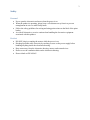
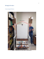
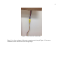
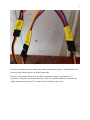
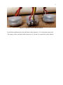
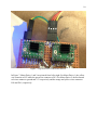
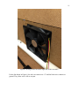
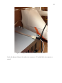
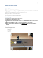
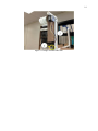
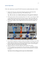
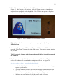
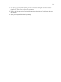
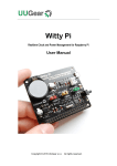
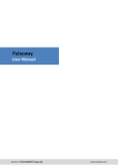
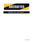
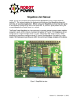
1 User Manual PICASSAU SENIOR DESIGN FALL 2013 November 20, 2013 Authored by: Ben Straub, David Toledo, Drew Kerr, Kayla Frost, Peter Gartland 2 Table of Contents Safety ............................................................................................................................................................ 3 Personal .................................................................................................................................................... 3 Product ...................................................................................................................................................... 3 Wiring the Product ........................................................................................................................................ 4 Connecting the Motors ............................................................................................................................. 4 Wiring Inside the Enclosure ...................................................................................................................... 7 System Set-Up and Storage ........................................................................................................................ 13 System Set-Up ......................................................................................................................................... 13 Product Storage ...................................................................................................................................... 13 System Operation ....................................................................................................................................... 15 Product Maintenance ................................................................................................................................. 19 Troubleshooting .......................................................................................................................................... 20 Linux ........................................................................................................................................................ 20 Common Software Errors ....................................................................................................................... 22 Reflashing the SD Card ............................................................................................................................ 22 Reprogramming the Arduino .................................................................................................................. 23 Mechanical Fixes ......................................................................................................................................... 25 3 Safety Personal Never open the electronics enclosure when the power is on. When the product is operating, please keep a safe distance away from it to prevent entanglement in wires or other bodily harm. Follow the safety guidelines for mixing and using paint written on the label of the paint bottles. As with all electronics, exercise caution when handling the electronics equipment associated with this product. Product DO NOT plug in or unplug the motors while the power is on. Discharge possible static electricity by touching a screw on the power supply before handling anything inside the electronics housing. Keep water away from the electronics housing, motors, and external wires. Do not cover the ventilation holes on the electronics housing. Do not climb on PICASSAU. 4 Wiring the Product Connecting the Motors Figure 1. Front side view of PICASSAU with indicators. 5 Figure 2. Detail of motor connections. Figure 2 is a close up image of the motor connections at the top of Figure 1. For correct orientation, ensure the blue wires on the right align. 6 Figure 3. Servo Motor Connections For correct orientation for each of the three connections shown in Figure 3, align the black wire on the top side with the purple wire on the bottom side. In Figure 3, the purple and red wires for all three connectors connect to ground and +5V, respectively. The green wire (left connection), yellow wire (middle connection), and blue wire (right connection) connect to D7, D8, and D6 on the Arduino, respectively. 7 Wiring Inside the Enclosure Figure 4. The pin diagram for the Arduino board. 8 Figure 5. Image of the connection wires for the IR sensor. The white cable connects to A0 on the Arduino, the black cable connects to ground, and the red cable connects to +5V. 9 Figure 6. A top-down view of the push buttons. For all three push buttons, the red and brown cables connect to +5V and ground, respectively. The orange, yellow, and white cables connect to A3, A2 and A1, respectively on the Arduino. 10 Figure 7. Top-down view of the motor drivers. In Figure 7, Motor Driver 1 and 2 are pictured from left to right. For Motor Driver 1, the yellow wire connects to D13 while the green wire connects to D12. For Motor Driver 2, the brown and red wires connect to ground and +5V respectively and the orange and yellow wires connect to D10 and D11, respectively. 11 Figure 8. Wiring for the fan on the right side of the enclosure. For the fan shown in Figure 8, the red wire connects to +5V and the black wire connects to ground. The yellow wire is left as an open. 12 Figure 9. Wiring for the fan on the left side of the enclosure. For the fan shown in Figure 9, the white wire connects to +5V and the black wire connects to ground. 13 System Set-Up and Storage System Set-Up 1) Mix paint at a ratio of 2 to 1 with water. 2) Rotate motor mount arm (Figure 11 (2)) 90° outward away from the canvas board to be parallel with the canvas. 3) Remove motor brake (Figure 11 (1)) and insert motor control wire. 4) Plug power cable to nearest power source. 5) Turn on power, turn key-switch (Figure 10 (1)). Product Storage 6) Turn off power, turn key-switch (Figure 10 (1)). 7) Unplug power cable from power source. 8) Disconnect motor controller wiring (Figure 11 (1)) and insert motor brake as shown in Figure 10. 9) Rotate motor mount arm (Figure 11 (2)) 90° inward toward the canvas board. 10) Rinse out paint cups, dry off paint cups until completely dry, and place paint cups inside housing. Product Dimensions (inches): Height: 79.5 Width: 27 Depth: 38 Figure 10. Image of key-switch and electronics enclosure. 14 Figure 11. Image of Motor and Arm. 15 System Operation Follow these simple steps to operate PICASSAU and paint an original painting from a webcam. 1. Position a 22”x28” piece of poster board using the paperclips at the bottom of the painting space and then the clip at the top. This will be the canvas. Tip: Make sure there are no bubbles and the poster is flat against the backboard. 2. Fill the paint containers below the backboard about 30% of the way up with paint. Make sure the light blue paint is placed in the left most container, orange in the middle, and dark blue on the right. See the Setup section above for how to mix paint. See Figure 12. 3. Fill the larger container on the far right about 80-90% full of water for cleaning. See Figure 12. Figure 12: Fill the containers with the correct liquids as indicated. 4. Ensure that all components are properly connected according to the Wiring section of this manual. Make sure that the wire connectors and not the brakes are on the stepper motors. 5. Position the brush carriage below the horizontal supports so that it is below the sight of IR sensor. Make sure it is near the center of the canvas. 6. Plug the main power cord from the right side of PICASSAU into a socket. 7. Put the key into the key switch and turn it clockwise 90 degrees. PICASSAU will turn on. You should hear the internal fans turn on, and the screen should show the computer booting up. Tip: Remove the key during operation to prevent accidental shutoff. 16 8. Wait for the computer to fully boot and the GUI to appear on the screen, as shown in Figure 13. This can take up to 2 minutes. After the picture appears, it can take some additional time to adjust the color thresholds. If the GUI does not appear at all, please refer to the Troubleshooting section of this manual. Figure 13: This is what the GUI will look like on startup Tip: A picture is taken when the computer boots up, so get ready when you turn PICASSAU on. 9. An image will appear on the GUI screen. If you would like to take a different picture, press the “Take Picture” button to the right of the screen. You can take as many pictures as you want. Tip: For portraits, features tend to be more defined if the face is angled as opposed to straight on. 10. Use the knobs to the right of the buttons to adjust the threshold values. The picture’s colors will update on the screen, but the actual picture will not. See Figure 14. A quick guide on how to use the threshold knobs: a. Turn the knobs slowly! It takes the internal computer time to process the image, so please try to be patient. b. A good rule of thumb is to have the knobs increasing in value from left to right (where fully counterclockwise is the minimum and fully clockwise is the maximum). An example of this is shown in the picture in Figure 14. c. If the knobs are set as indicated in (b), they can be used as follows: 17 i. The leftmost knob adjusts the threshold between dark blue and light blue 1. For less dark blue, turn counterclockwise 2. For less light blue, turn clockwise ii. The middle knob adjusts the threshold between light blue and orange 1. For less light blue, turn counterclockwise 2. For less orange, turn clockwise iii. The rightmost knob adjusts the threshold between orange and white 1. For less orange, turn counterclockwise 2. For less white, turn clockwise Figure 14: Adjust the threshold knobs to control the colors of the image. Tip: Maximize the amount of white background in your picture to cut down on painting time. 11. When you are satisfied with the image, press the “Continue” button. 12. The next screen will ask if you are sure. If you want to paint your picture, press the “Paint Now” button. If you want to go back and adjust your picture more, select the “Go Back” button. 13. Once you select the “Paint Now” button, PICASSAU will begin its calibration routine. While it is doing this, the internal computer is processing the image. If processing takes longer than the calibration routine, the carriage might seem to idle. Depending on the complexity of the image, processing can take several minutes before painting begins, so please be patient. 14. Next, PICASSAU will paint the picture! Tip: Make sure to monitor PICASSAU while it is painting. Make sure it does not spill the paint receptacles and guide the carriage into the container if necessary. Also, be prepared to add more paint to the receptacles if necessary. 15. When PICASSAU is finished, it will rinse its brush off in the water container. 16. If you wish to paint another picture, replace the canvas, clean the paintbrush, refill the paints, and replace the water. See the Maintenance section for more information. Then you can go back to the GUI and take a new picture to repeat the painting process. 18 17. Use the key to turn off PICASSAU. Remove and clean the liquid containers and the paintbrush. When clean, replace all components. 18. Refer to the Storage section for detailed instructions about how to break down and store PICASSAU. 19. Enjoy your original PICASSAU paintings! 19 Product Maintenance 1. The paint cups should be rinsed out after every painting and replaced only when necessary. a. To replace cups, purchase a .5 liter bottle of water, empty contents, and cut off top 2 inches of cup with lid. 2. The paint brush needs to be rinsed by hand after each painting is complete and replaced when necessary. a. To replace paint brush simple remove four screws and nuts (see Figure 15), and replace with new brush. i. Brush should be ½ an inch wide, and 4 ¾ inches long. Figure 15. Image of paint brush holder. 20 Troubleshooting Linux While debugging PICASSAU it may at times be useful to log into the underlying operating system. PICASSAU runs the Raspbian operating system, a modification of Debian Linux specifically targeting the Raspberry Pi. Because PICASSAU is set up to boot directly into the GUI program, it can be difficult to gain access to the operating system. This can, however, be accomplished by the following steps. 1. Plug a keyboard and a mouse (optional, if desired) into the USB ports of either the Raspberry Pi or the USB hub plugged into the Pi. It is advised that you do not plug in additional unpowered USB hubs into the Raspberry Pi, as the increased power draw may cause the Pi to reboot. If additional USB ports are desired (for devices like wireless adapters or flash drives), it is recommended that you use a powered USB hub. 2. Turn on PICASSAU and wait for it to boot up into the user interface screen. 3. On the keyboard simultaneously press [Ctrl] + [Alt] + [F2]. This will change the screen to a black terminal. 4. You will be prompted for a username (login) and password, as shown in Figure 16. These are Username: picassau Password: picassau Figure 16: Username prompt on the Raspberry Pi. 5. If you only desire to use the command line, then you may stop here. However, if you want to use the graphical desktop interface, continue to step 6. 6. You will need to find the process that the GUI is running on. This can be accomplished through the following command: ps aux | grep “GUI” 21 Note that the vertical line in the middle is called the “pipe” character, is made using [SHIFT] + \ on standard US keyboards. 7. Several processes will be listed, as seen in Fig. 17. You need to obtain the process ID number from either of the first two processes. The process ID number is shown circled in Fig. 17. Figure 17: A screenshot of the process ID for the GUI. It also shows killing the process. 8. Kill the process by using the command sudo kill [process ID] Where the process ID number goes in place of “[process ID]”. For example: sudo kill 2413 You will likely be prompted again for the password, which is still “picassau”. 9. Now switch back to the graphical desktop by simultaneously pressing [Ctrl] + [Alt] + [F7]. If you still see the normal PICASSAU interface screen, then you were unsuccessful in killing the process. Hit [Ctrl] + [Alt] + [F2] and repeat steps 6 – 9. After logging into the operating system, the user has the ability to make many changes, some of which may break the functionality of PICASSAU. It is recommended that you be careful while logged into the base operating system. However, any changes to the Raspberry Pi and its operating system can be undone by reflashing the SD card. This process is described in the “Reflashing the SD Card” section. 22 Common Software Errors The computer starts to boot up but then repeatedly reboots before it gets to the GUI. o This could be a power issue. Make sure that it is powered appropriately. There should be a micro-USB cable connected from the RPi into the USB hub, which is then plugged into one of the RPi’s USB ports. The red and black wires coming out of the USB hub should connect to 5V and GND on the breadboard. o This could occur if the SD card has become corrupted. Follow the steps in the “Reflashing the SD Card” section. The computer boots up to a desktop, but the GUI never actually comes up. OR the GUI comes up, but then crashes. o This can occur if the USB devices are unplugged. Make sure that both the USB webcam and the USB-to-serial cable going to the Arduino are both plugged into the USB hub, and that the USB hub is plugged into the RPi. o This can occur if the USB devices are damaged or malfunctioning. Try unplugging the USB webcam and plugging in a different one. If this does not work, try swapping out the USB-to-serial cable, if available. o This could occur if the SD card has become corrupted. Follow the steps in the “Reflashing the SD Card” section. Screen does not turn on o Make sure that the video cable and power are connected properly. Refer to the “Wiring” section. Reflashing the SD Card During the normal course of operation, it is possible for the sensitive flash memory of the SD card to become corrupted. In particular, excessive cycles of powering on and off can corrupt the SD card. Additionally, changes made manually by accessing the underlying operating system (as described previously in Troubleshooting: Linux) can cause PICASSAU to lose functionality. These problems can all be fixed by reflashing the SD, which returns the file system to its original state. This section lists the steps for completing this process. The steps described for completing this process has some requirements. Firstly, a Windows XP, Windows Vista, Windows 7, or Windows 8 is required. Additionally, an SD card reader (either built-in or USB) on your computer is required. 1. Download the latest SD card flash image. This can be found by going to PICASSAU’s website (http://picassau.weebly.com), going to “Project Documents”, and clicking the “SD Card Image” listed under “Source Code”. Download the file and save it somewhere that you can find it. 2. Install Win32DiskImager. This can be found at: http://sourceforge.net/projects/win32diskimager/ 23 Follow the instructions provided to install it. 3. Insert your SD card into your installed card reader. Make sure you know which drive letter corresponds to this SD card. It is important to know the correct drive, as choosing the wrong drive letter could permanently erase other drives on your computer. 4. Run Win32DiskImager. 5. Select the device letter in drop-down box under “Device”. See Fig. 18 for an example. Again, selecting the wrong device could overwrite important data on your system. 6. Select the image file. This can be done by clicking on the small folder icon next to the text box below “Image File”. Navigate to and select the image file that was downloaded in step 1. Figure 18: Win32DiskImager screenshot. This tool is used to reflash the SD card. 7. Before continuing, make sure you have the correct file and device selected! 8. Click on the “Write” button. The disk will begin writing. This may take several minutes. 9. When it finishes writing, you can eject your SD and insert it back into the Raspberry Pi. The file system on the RasPi is not back to its original state. Reprogramming the Arduino During normal operation, the user should never need to reprogram the Arduino. However, advanced users may want to reprogram the Arduino in cases such as replacing the Arduino with a new one or altering the embedded Arduino code. While this is not recommended for typical users, the Arduino code is made freely available. The code can be found directly on our Github repository at https://github.com/PICASSAU/PICASSAU. It can also be found linked on the project documents page of the PICASSAU website: http://picassau.weebly.com. 24 To program the Arduino, an FTDI USB-serial cable or some other USB to 5V RS232 cable is required. One of these cables can be found in PICASSAU, between the Raspberry Pi and the Arduino. It can be used to program the Arduino by unplugging it from the RasPi and plugging it into your own computer, but the cable should be returned to its original configuration before attempting to run PICASSAU. Running PICASSAU without the serial cable will cause the PICASSAU GUI to crash. Additionally, you will need to download and install the Arduino IDE. This can be found in the downloads portion of the Arduino website: www.arduino.cc The relevant Arduino code can be opened by downloading the previously mentioned Github repository and navigating to “[Repository location]/PICASSAU/picassau/” and opening “picassau.ino”. To program the Arduino, you need to select the serial port (this can be determined by seeing which port appears after plugging in the serial cable) and the type of board. The Arduino board in PICASSAU is equivalent to the “Arduino Duemilanove w/ ATmega328”. From this point, clicking “Upload” should compile and upload the code. However, if using the hand-made serial cable included inside PICASSAU, it is necessary to hit the reset button on the Arduino just after it finishes compiling and before it uploads. This can be determined easily by watching for the white text to say “Binary sketch size: [size] bytes (of a 30,720 byte maximum)” in the message pane. As soon as this text appears, the reset button on the Arduino should be pressed and released. 25 Mechanical Fixes Adjusting fishing line o If the fishing lines become imbalanced, causing the brush carriage to tilt, the lengths of the back two fishing lines can be adjusted with the plastic “S” fittings to right the carriage again. Calibration o For best results Move the brush carriage below and about a foot to the right of the IR sensor. o Adjusting IR sensor If PICASSAU has trouble calibrating itself, make sure the IR sensor is situated horizontally on the PVC pipe. o Paper on carriage Make sure the white poster paper is secured flush against the left side of the brush carriage.