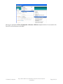
1
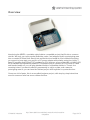
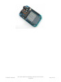
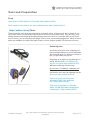
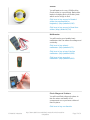
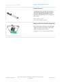
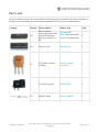
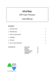
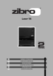
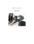
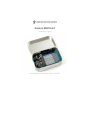
Adafruit MENTA Kit
Created by Ladyada
Last updated on 2014-03-16 12:30:17 AM EDT
Guide Contents
Guide Contents
2
Overview
3
Make It!
5
Tools and Preparation
6
Prep
6
(http://adafru.it/cmj)Tools
6
Parts List
9
Soldering & Assembly
13
Use it!
28
Powering it!
28
Use with Arduino IDE
28
Download
31
Software
31
© Adafruit Industries
http://learn.adafruit.com/adafruit-menta-kit-mint-tin-arduinocompatible
Page 2 of 31
Overview
Introducing the MENTA, a portable minty Arduino-compatible project that fits into a common
mint tin. We took our super popular Boarduino series, and wrapped it with a prototyping area
into a rounded PCB that slots directly into an Altoids-sized metal tin. We included everything
you expect to jump-start your project: a DC power adapter with polarity protection, beefy 1
Amp 5V regulator and 250mA 3.3V regulator for 3.3V devices, green power LED, red blinky LED,
ISP-6 standard reprogramming header, FTDI interface plug to connect an FTDI Friend or cable
and female header so you can plug standard Arduino-compatible shields in. There's four
mounting holes if you want to attach it permanently to a box or plate, and a massive
prototyping area so you can have the finished project all fit together in a protective box.
Comes as a kit of parts, this is an excellent beginner project, with step-by-step instructions
even for someone who has never soldered before.
© Adafruit Industries
http://learn.adafruit.com/adafruit-menta-kit-mint-tin-arduinocompatible
Page 3 of 31
© Adafruit Industries
http://learn.adafruit.com/adafruit-menta-kit-mint-tin-arduinocompatible
Page 4 of 31
Make It!
This kit is pretty simple, but you should follow these steps fully so that you'll have no problems!
1. Tools and preparation (http://adafru.it/cmg)
2. Check the parts list (http://adafru.it/cmh)
3. Assemble the kit (http://adafru.it/cmi)
© Adafruit Industries
http://learn.adafruit.com/adafruit-menta-kit-mint-tin-arduinocompatible
Page 5 of 31
Tools and Preparation
Prep
Learn how to solder with tons of tutorials (http://adafru.it/aTk)!
Don't forget to learn how to use your multimeter too (http://adafru.it/aOy)!
(http://adafru.it/cmj)Tools
There are a few tools that are required for assembly. None of these tools are included. If you
don't have them, now would be a good time to borrow or purchase them. They are very very
handy whenever assembling/fixing/modifying electronic devices! I provide links to buy them,
but of course, you should get them where ever is most convenient/inexpensive. Many of these
parts are available in a place like Radio Shack or other (higher quality) DIY electronics stores.
So ldering iro n
Any entry level 'all-in-one' soldering iron
that you might find at your local hardware
store should work. As with most things in
life, you get what you pay for.
Upgrading to a higher end soldering iron
setup, like the Hakko FX-888 that we
stock in our store (http://adafru.it/303),
will make soldering fun and easy.
Do not use a "ColdHeat" soldering iron!
They are not suitable for delicate
electronics work and can damage the kit
(see here (http://adafru.it/aOo)).
Click here to buy our entry level
adjustable 30W 110V soldering
iron. (http://adafru.it/180)
Click here to upgrade to a Genuine
Hakko FX-888 adjustable temperature
soldering iron. (http://adafru.it/303)
© Adafruit Industries
http://learn.adafruit.com/adafruit-menta-kit-mint-tin-arduinocompatible
Page 6 of 31
So lder
You will want rosin core, 60/40 solder.
Good solder is a good thing. Bad solder
leads to bridging and cold solder joints
which can be tough to find.
Click here to buy a spool of leaded
solder (recommended for
beginners). (http://adafru.it/145)
Click here to buy a spool of lead-free
solder. (http://adafru.it/734)
Multimeter
You will need a good quality basic
multimeter that can measure voltage and
continuity.
Click here to buy a basic
multimeter. (http://adafru.it/71)
Click here to buy a top of the line
multimeter. (http://adafru.it/308)
Click here to buy a pocket
multimeter. (http://adafru.it/850)
Flush Diago nal Cutters
You will need flush diagonal cutters to
trim the wires and leads off of
components once you have soldered
them in place.
Click here to buy our favorite
© Adafruit Industries
http://learn.adafruit.com/adafruit-menta-kit-mint-tin-arduinocompatible
Page 7 of 31
cutters. (http://adafru.it/152)
So lder Sucker
Strangely enough, that's the technical
term for this desoldering vacuum tool.
Useful in cleaning up mistakes, every
electrical engineer has one of these on
their desk.
Click here to buy a
one. (http://adafru.it/148)
Helping Third Hand With Magnifier
Not absolutely necessary but will make
things go much much faster, and it will
make soldering much easier.
Pick one up here. (http://adafru.it/291)
© Adafruit Industries
http://learn.adafruit.com/adafruit-menta-kit-mint-tin-arduinocompatible
Page 8 of 31
Parts List
Check to make sure your kit comes with the following parts. Sometimes we make mistakes so
double check everything and email [email protected] if you need replacements!
Image
Name
Mo re Info
Qty
IC1
Microcontroller
(preprogrammed with
Arduino bootloader
when purchased in a
kit)
ATmega328P20PU (unprogrammed)
IC1'
28-pin socket
28 pin socket
1
X1
16.00 MHz ceramic
oscillator
16 mhz ceramic
resonator
1
2.1mm Power Jack
CUI PJ-202AH
1
1N4001 diode
Generic 1N4001
1
D1
© Adafruit Industries
Descriptio n
Adafruit (Programmed)
http://learn.adafruit.com/adafruit-menta-kit-mint-tin-arduinocompatible
1
Page 9 of 31
5V regulator
IC3
IC2
C1 C2
C3 C4
7805 TO-220 package
3.3V regulator
MCP1700-330 TO-92
Package
7805
1
MCP1700-3302E/TO
1
Ceramic Capacitor
4
Electrolytic Capacitor
1
Electrolytic Capacitor
2
Bypass capacitor
0.1uF ceramic
Electrolytic capacitor
C5
47uF / 25V
(or higher)
100uF/6.3V capacitor
(or higher)
C6 C7
© Adafruit Industries
(the image shows a
http://learn.adafruit.com/adafruit-menta-kit-mint-tin-arduinocompatible
Page 10 of 31
10V but 6.3V is fine)
© Adafruit Industries
R1
10K ohm 1/4W 5%
resistor (brown black
orange gold)
Generic Resistor
1
R2 R3
1.0K 1/4W 5% resistor
(brown black red gold)
Generic Resistor
2
D3
3mm red LED
3mm red diffused
1
D2
3mm green LED
3mm green diffused
1
SW1
6mm tact switch button 6mm tact switch
1
ICSP
6 pin header, 0.1"x0.1"
2x3 pin header
spacing
1
36 pin male header,
0.1" spacing
1
0.1" male header strip
Jumper
1
6-pin Female Header
2
http://learn.adafruit.com/adafruit-menta-kit-mint-tin-arduinocompatible
Page 11 of 31
8-pin Female Header
PCB
© Adafruit Industries
2
Bumpers
Adafruit Industries
4
Circuit board
Adafruit Industries
1
http://learn.adafruit.com/adafruit-menta-kit-mint-tin-arduinocompatible
Page 12 of 31
Soldering & Assembly
Prepare to assemble the kit by checking
the parts list and verifying you have
everything!
Next, heat up your soldering iron and
clear off your desk.
Place the circuit board in a vise so that
you can easily work on it.
The first component we will be placing is
called R3 and it's right in the middle of
the PCB. R3 is a 1000 ohm (1Kohm)
resistor - with Brown, Black, Red, Gold
stripes. Be careful you don't confuse it
with the 10K resistor which has an orange
stripe. If you're not sure, use a
multimeter to check!
This resistor sets the brightness of the
red LED that's used by the Arduino to
indicate when it's bootloading
(downloading sketches).
Bend the resistor into a 'staple' shape
and place it in the slot indicated, right
over the resistor-shaped silkscreen
image. Resistors do not have polarity so
no worries about putting it in backwards,
they work the same either way.
© Adafruit Industries
http://learn.adafruit.com/adafruit-menta-kit-mint-tin-arduinocompatible
Page 13 of 31
Bend out the long metal leads so the
resistor sits flat agains the board, and flip
the PCB over.
Now we will solder in the first part. Heat
up your soldering iron (about 700
degrees F is common but you may need
to adjust it higher for lead-free).
Using your soldering iron tip, press and
heat both the pad (the silver ring around
the hole) and lead (wire) at the same
time for 2 or 3 seconds. Then poke the
end of the wire into create a nice solder
joint. Do this for both leads.
© Adafruit Industries
http://learn.adafruit.com/adafruit-menta-kit-mint-tin-arduinocompatible
Page 14 of 31
Using your diagonal cutters, cut off the
long leads just above the solder joint.
Now we can do the other two resistors.
Start with R2 - another 1.0K ohm resistor
(Brown Black Red Gold) and then R1
(Brown Black Orange Gold)
R2 is used to set the brightness of the
green LED, which indicates when the
board is correctly powered.
R3 is used as part of the reset circuitry it keeps the Arduino chip active when
you want to and helps reset it when the
RESET button is pressed
Bend and place them in the slots labeled
R2 and R3.
© Adafruit Industries
http://learn.adafruit.com/adafruit-menta-kit-mint-tin-arduinocompatible
Page 15 of 31
Flip over the PCB and solder the 2
resistors.
Clip the two resistors' leads.
Next we will solder in the ceramic
capacitors. Ceramic capacitors are used
for high frequency filtering and noise
reduction. They'll keep the power supply
system stable even if you're doing high
current stuff like motors, or really big
LEDs.
The ceramic capacitors are yellow blobs,
place them in location C1 C2 C3 and
C4.
Like resistors, ceramic capacitors are not
polarized so they can be inserted either
way and will work fine.
Bend out the leads like the resistors to
keep them flat against the PCB.
© Adafruit Industries
http://learn.adafruit.com/adafruit-menta-kit-mint-tin-arduinocompatible
Page 16 of 31
Solder all the capacitor leads.
Clip them short just like the resistors.
Next up we will place the RESET button this is what you press to reset the Menta,
say if you want to start the program over.
Buttons are symmetric, and they only fit
the holes one way, so just press it into
place and it should snap in.
© Adafruit Industries
http://learn.adafruit.com/adafruit-menta-kit-mint-tin-arduinocompatible
Page 17 of 31
Solder all 4 legs of the button, no need to
clip them as they are already quite short.
Now we will place our first non-symmetric
component, a diode! The diode only
conducts current in one direction. We
use this diode for protecting the Menta since it can only work in one direction it
makes sure we don't connect negative
voltages into the DC plug that could
damage or destroy the electronics. This
particular diode is a 1N4001 model,
which is extremely common power diode
that can handle over an Amp of current.
Diodes have a stripe to indicate the
'cathode' - this one has a silver stripe.
Make sure the silver stripe matches the
little white stripe on the silkscreen. In this
image, it's on the right hand side. Double
check you get this right because
otherwise nothing will work and it will be
very confusing!
Solder in the diode and cut the long
wires.
© Adafruit Industries
http://learn.adafruit.com/adafruit-menta-kit-mint-tin-arduinocompatible
Page 18 of 31
Now that we have the diode in place we
can solder in the voltage regulator. This
regulator takes a high voltage (7VDC up
to 25VDC) and regulates it down to 5V.
The Menta circuitry requires a nice clean
5VDC to run, any more could burn it up.
The regulator is kind of like a 'bouncer'
that keeps the delicate Menta chip from
having to see more than 5VDC. This
particular regulator is the very common
7805 in a big package, it can handle up
to 1 Ampere of current. Place it flat on its
back so that it matches up close to the
silkscreen image below, make sure you
can read the part number on top.
Don't worry if it doesn't line up perfectly,
the hole isn't used for anything (it can be
used for heat sinks but it's not necessary
for us).
Solder in the three legs and clip them
short when done.
Next we will place the polarized
electrolytic capacitors. These are the
beefy versions of the ceramic capacitors
we already placed. Ceramics are good
for high frequency noise, and the
electrolytics are good for low frequency
noise, that's why we team them up
together to cover all frequencies.
Electrolytic capacitors are polarized they must be put in the correct way or
they will be damaged so be super careful
here.
Capacitors have one leg that's longer
than the other, this is the po sitive lead.
Place the positive lead in the hole marked
with a tiny + next to it. See the images to
the left of how to place the three
capacitors.
The first one is C5 which is a 25V 47uF
one (it's bigger than the others) for
filtering the incoming power from the DC
power jack. The other two, C6 and C7
are smaller 6.3V 100uF for filtering the 5V
and 3.3V supplies.
Yo u may want to bend o ver C5 so
it lies do wn a little mo re flat
against the bo ard, befo re
© Adafruit Industries
http://learn.adafruit.com/adafruit-menta-kit-mint-tin-arduinocompatible
Page 19 of 31
so ldering, it will help make so me
shields fit!
After you've triple-checked the polarity
of the capacitors, flip over the PCB and
solder them in.
Clip the leads when done.
Now we will solder in the indicator LEDs.
These LEDs are the Menta's way of telling
you what's going on. LEDs are Light
Emitting Diodes - which means that like
the 1N4001 they have a polarity and
won't work if placed backwards. Like
capacitors, the also have a longer wire
that indicates the po sitive lead. Place
this wire in the hole marked with a +.
First we will place the green LED, this is
the power indicator LED.
Then place the red LED, this is the "pin
13"/bootloading indicator LED.
© Adafruit Industries
http://learn.adafruit.com/adafruit-menta-kit-mint-tin-arduinocompatible
Page 20 of 31
Solder both LEDs in, clip the leads when
done.
Now we can place the big power jack.
This is how we can plug in a battery or
power adapter.
The power adapter has big flat pins,
these are both so it can pass a lot of
current and also so it will stay
mechanically attached to the board, use
a lot of solder to fill in the big pads
completely.
© Adafruit Industries
http://learn.adafruit.com/adafruit-menta-kit-mint-tin-arduinocompatible
Page 21 of 31
Next up is the 16.00 MHz crystal X1. This
crystal is what lets the Menta chip run at a
brisk 16 million clocks per second. This
oscillator comes in a orange shape with
three pins. Luckily, it's symmetric so just
place it any way you like.
Then bend the leads, flip over the PCB
and solder it in. When done, clip the
leads.
Now we're at the toughest part of the kit.
Luckily we have done so many parts so
far you should be a little comfortable with
the iron.
We're going to place the header in the
PCB. The problem with header is the
leads are so short you can't bend them
when flipping the PCB over, so we'll use
tape or if you have something like clay or
playdough or tack that works well as well.
Take the long stick of 'break-away'
header and break off 6-pin and 3-pin
piece. You can keep the rest for a future
project, its handy stuff.
© Adafruit Industries
http://learn.adafruit.com/adafruit-menta-kit-mint-tin-arduinocompatible
Page 22 of 31
Place one piece of the header, the 6-pin
piece, into the spot right next to the
green LED. Make sure the short legs are
sticking down into the PCB and the long
legs are sticking up. This is the
programming header. This is where you
can connect an FTDI cable or FTDI friend
to reprogram the Menta.
Place the 3-pin piece right below that, in
the PWR_SEL spot - this is for selecting
whether you want to power from the FTDI
cable or from the DC jack.
Finally, find the 2x3 header and place that
into the ICSP spot - this is for if you want
to use an AVR programmer such as a
USBtinyISP, Dragon, etc to program the
AVR chip.
Then use your favorite tape to hold the
parts in place. Masking tape works better
than cellotape but use what you have (I
only had cello tape on my desk).
Flip over the PCB, check that the header
is still in place, solder all the short leads
in. You won't need to clip them because
they ought to be very short already.
© Adafruit Industries
http://learn.adafruit.com/adafruit-menta-kit-mint-tin-arduinocompatible
Page 23 of 31
Finally you can place the jumper into the
PWR_SEL spot. For now, place it on the
right hand side, in the DC position - this
indicates that you'll be powering it via the
big DC jack.
Now we can do a test, find a DC power
adapter, 7VDC or higher, with a 2.1mm
jack and center-polarity (these are nearly
standard) and plug it in. With the jumper
in place, you should see the Green LED
light up. If not, something is wrong either the LED is in backwards or your
power supply isn't working. Go back and
check your work until you can figure out
what happened.
Once you know the 5V power supply is
working, we can continue. Next up we will
solder in the 3.3V regulator. This will let
us power the many 3.3V sensors and
accessories out there, a nice little extra!
The chip we'll be using is the MCP1700330 - you should be able to see this
marking on the face of the little chip. This
regulator can supply up to 250mA, which
is plenty for nearly any device you'll be
using. Place the chip so that the flat face
matches the flattened image
silkscreened on the PCB.
Next, we will be placing the 28-pin socket
next to it. This socket is a mechanical
'holder' - it holds the ATmega328 chip
that drives the Menta. We socket it for a
few reasons - one to protect the chip, to
make it easier to replace in case of
damage, and so that you don't have to
worry about accidentally soldering it in
backwards. If you mess up on the
socket, it's a lot easier to fix than if you
do the same with the chip.
The socket has a little half-moon notch
on one end. Make sure that this notch
matches the notch on the silkscreen - it
will help you align the chip later. If you get
this wrong, don't try to remove the
socket, just keep going.
© Adafruit Industries
http://learn.adafruit.com/adafruit-menta-kit-mint-tin-arduinocompatible
Page 24 of 31
Solder in all 28 pins of the socket and the
3.3V regulator.
Clip the regulator leads. The socket does
not need to be clipped.
Now we can place the ATmega328 chip the brains of the Menta. Chips come with
the legs in an A shape, but we want it in
more of an H shape. Pick the chip out of
the antistatic foam and holding it by the
ends, bend the leads against the table to
flatten them parallel.
Once they are straight, it will be easy to
fit them into the socket. Make sure you fit
it in the right way, as it's symmetric. One
end has a half-moon cut out of it, this
should be on the left side in the photos,
matching with the notch in the socket and
in the silkscreen.
© Adafruit Industries
http://learn.adafruit.com/adafruit-menta-kit-mint-tin-arduinocompatible
Page 25 of 31
Now we can do a second test, to check
the chip and crystal are working right.
Plug in the board again to the DC power
and press the reset button, you should
see the red LED flashing a few times.
Every time you press the button it should
flash again.
Once you're happy, remove the DC
power and we can finish up.
This part is o ptio nal, but if yo u
want to plug in shields, yo u'll want
to co mplete it. If yo u want a mo re
co mpact Menta, skip it!
Like the Arduino, the Menta has the ability
to take 'shields' - pluggable add-ons to
increase the functionality. If you want to
have this ability, grab the two 8-pin
female headers and two 6-pin female
headers and place them in the o uter
pins marked "Digital I/O" and "Analog I/O"
- there are two sets of pins so be sure to
use the OUTER ones!
If you have a shield handy, you can plug it
in now to test the fit, and hold the female
headers straight while you solder them
in. Otherwise, use tape or if you're
dextrous, hold the header with one finger
while soldering.
Solder in the 4 sets of header, all of the
pins!
© Adafruit Industries
http://learn.adafruit.com/adafruit-menta-kit-mint-tin-arduinocompatible
Page 26 of 31
Finally, you can finish your kit by placing
the four rubber bumpers over the
mounting hole spots. These will keep the
Menta off your desk to avoid scratching
it, or accidentally shorting against a piece
of wire.
That's it! You're done! Now you can read
the User Manual for details on how to
upload your favorite Arduino sketches.
© Adafruit Industries
http://learn.adafruit.com/adafruit-menta-kit-mint-tin-arduinocompatible
Page 27 of 31
Use it!
Powering it!
Before you can even upload sketches, you must have the jumper set right. If you want to
power it from the DC jack, place the jumper on the DC side of the 3-pin header. If you're going
to power it via the FTDI connector, place it in the USB side. The jumper is to the left of the
RESET button.
Make sure that the green LED is lit once you have the board powered, if the green LED is off,
there's no power - check your adapter or battery or cable and get the LED lit before continuing.
Use with Arduino IDE
OK so now you want to upload code, right? First up, you will need an FTDI
Friend (http://adafru.it/284) or FTDI Cable (http://adafru.it/70) to talk to the computer via USB. If
this is your first time using an FTDI adapter, you will want to follow our little tutorial on
downloading and installing the drivers (includes download for FTDI drivers) (http://adafru.it/cl3) drivers are required!
If you're using an FTDI cable, connect it so that the black wire is next to the silkscreen text blk
and the green wire is next to the grn text (you can also remember it's next to the Green LED. If
you're using an FTDI friend, match up the texts (both say black and green).
© Adafruit Industries
http://learn.adafruit.com/adafruit-menta-kit-mint-tin-arduinocompatible
Page 28 of 31
Connect the FTDI adapter to your computer and start the IDE. Select the COM or /dev/tty port
that is created when you plugged in the FTDI adapter.
Be sure to select Arduino Duemilanove w/ATmega328 as the board!
© Adafruit Industries
http://learn.adafruit.com/adafruit-menta-kit-mint-tin-arduinocompatible
Page 29 of 31
Now try to upload the File->Examples->Basics->Blink example sketch. If successful, the
Red LED on the Menta should blink.
© Adafruit Industries
http://learn.adafruit.com/adafruit-menta-kit-mint-tin-arduinocompatible
Page 30 of 31
Download
Software
If you're using an FTDI Friend (http://adafru.it/284) or FTDI Cable (http://adafru.it/70), you will
want to follow our little tutorial on downloading and installing the drivers (includes download for
FTDI drivers) (http://adafru.it/cl3).
© Adafruit Industries
Last Updated: 2014-03-16 12:30:19 AM EDT
Page 31 of 31