1
Instruction Manual
SyCore / PC104
- Manual Release V 6.11 -
Serial No.:
UO467 12/0 0613
The manufacturer can not be held liable for incorrect statements and their consequences; subject to change !
User Manual SyCore
1. General Instructions
2. Safety
3. SyCore
3.1. Front Panel
3.2. Rear Panel
3.3. Operation
4. Oscillators
4.1. Function Diagram
4.2. Generation of Low-Frequency AC Voltages
4.3. Generation of High-Frequency AC Voltages
4.4. Basic Adjustment
4.5. Basic Functions
4.6. Flicker Simulation (in Connection with Opt. „Multiplier“)
4.7. Special Functions
5. Measurement
5.1. RMS
5.2. Frequency Measurement
5.3. Oscilloscope
6. Control
6.1. Amplifier
6.2. Enhanced Amplifier Functions
6.3. Parallel Connection (optional)
6.4. Impedance (optional)
6.5. Current Limitation (optional)
6.6. Resistor Load (optional)
6.7. Amplifier Selection (optional)
6.8. Safe Communication with Amplifier (optional)
7. Macros
7.1. Execute Macros
7.2. Store Macros
7.3. List Macros
7.4. Load Macros
7.5. Save Macros
7.6. Overwrite Macros
8. Set-up
8.1. Adjustment of the Interface address
8.2. Info
9. IEEE488 Interface
9.1. Command Syntax
9.2. Command Synchronization
9.3. List of Commands
9.4. Oscillator
9.5. Page Control List
9.6. Measurement
9.7. Control
9.8. Input-/Output Port (optional)
9.9. Interface
10. Pin Assignment
10.1. Link In/Out
10.2. IEEE488
10.3. Control
10.4. Analog I/O
10.5. RU_Control
3
3
3
4
5
6
10
10
11
11
11
12
16
17
22
22
28
29
31
31
32
33
34
35
36
37
38
39
39
39
39
40
40
40
42
42
42
43
43
44
45
48
77
96
105
121
123
130
130
131
132
133
133
16.07.2013 E_SYC_V6_11.doc
Spitzenberger & Spies GmbH & Co. KG
Page 1
User Manual SyCore
10.6. Digital I/O (Event Trigger)
11. Technical Data
11.1. Oscillator
11.2. Multiplier
11.3. Measurement
11.4. General
12. Index
13. Annex
134
137
137
138
138
140
141
144
16.07.2013 E_SYC_V6_11.doc
Spitzenberger & Spies GmbH & Co. KG
Page 2
User Manual SyCore
1. General Instructions
This device has been shipped in perfect safety condition. However, it has to be checked for
mechanical defects before the first start-up. If there is any transportation damage, please
inform Spitzenberger & Spies immediately. In that case the device shall not be put into
operation before contacting Spitzenberger & Spies and getting instructions how to carry on.
Reference: To avoid malfunctions the default values must only be changed by
Spitzenberger & Spies service technicians ! Exception: IEEE address.
2. Safety
The device must only be operated by instructed personnel !
Energized parts might be uncovered when opening the housing. Before opening the device the
mains input cable has to be disconnected from the supply voltage due to safety regulations.
The chassis ground of the device is connected to earth.
3. SyCore
SyCore (system core) is an all-round control and measurement device. Similarly to a
computer it is able to undertake several functions.
• device control unit (for voltage and current amplifiers)
• oscillator unit (for voltage and current amplifiers)
• measurement unit (for voltage and current amplifiers)
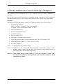
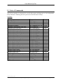
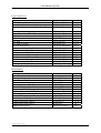
The firmware of the device supports the following options:
Device option
Function in the menu
One oscillator card
Oscillator
Two oscillator cards
Oscillator
Multiplier
Oscillator | Trig/Sync/Add/Mult
Measuring card
Measurement
Current limit card
Control | Current Limit
Amplifier
Control | Amplifier
Impedance
Control | Impedance
Parallel Connection
Control | Parallel Conn
Resistor Load
Control | R-Load
Caution:
The functions must only be performed when the referring options available,
otherwise malfunctions might occur.
16.07.2013 E_SYC_V6_11.doc
Spitzenberger & Spies GmbH & Co. KG
Page 3
User Manual SyCore
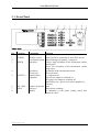
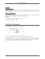
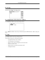
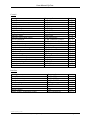
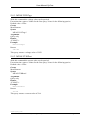
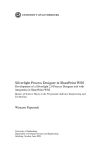
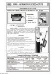
3.1. Front Panel
Pos. Lettering
1
2
3
4
5
6
7
8
Component
Function
POWER
Tumbler switch
Mains switch for switching on and off the device
Incremental switch Manual tuning of frequency, voltage etc.
SPEED
Indication
Yellow: high resolution of the incremental switch
(small steps)
Green: low resolution of the incremental switch
(large steps)
Speed keys
Resolution of the incremental switch
Cursor keys
Menu selection
OUTPUT ... Function keys
e.g. output on/off
Indication
On (red): the output is switched on
Off (green): the output is switched off
Both LEDs (red + green): at least one amplifier is
overload
ESC, DEL ... Numeric keyboard Input
HELP
Soft-keys
Menu direct switching
Display
for indication of the menu, setting values and
measured values
16.07.2013 E_SYC_V6_11.doc
Spitzenberger & Spies GmbH & Co. KG
Page 4
User Manual SyCore
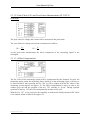
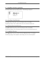
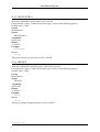
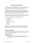
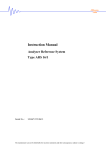
3.2. Rear Panel
Pos. Lettering
Component
Function
9
LINE ~
10
RU_CONTROL
11
SPS
12
13
RS232
IEEE488
14
15
16
CONTROL
ANALOG I/O
EXT. INPUT
17
OUTPUT P4
Rubber connector for non- Mains supply
heating apparatus with 1A
fuse
Connector socket
Mains control
series 692/6+PE
(additional device e.g. amplifier
type PAS)
Socket 25-pole SUB-D
Interface SPS
with trigger assignment
Not fitted
Micro Ribbon 24-pole type IEEE-488-socket
Ansley
Plug 25-pole SUB-D
Control output
Socket 25-pole SUB-D
Signal input/output
Safety lab socket
External input (1), (2)
Input impedance approx. 10kΩ
Safety lab socket
Oscillator output 4th phase (1)
(1)
Input and Output signals are related to earth. In order to avoid beat or similar resulting
from GND loops you are recommended to use an unearthed function generator (laboratory:
an external generator with isolation transformer may be used).
(2)
The external input is designed as adder input to the internal oscillator/oscillators.
Harmonics can be easily generated with this adder input. The adder function is
continuously available and therefore doesn´t need to be enabled.
Reference: The above shown front and rear panel diagrams and descriptions contain all
components and options available for the device.
16.07.2013 E_SYC_V6_11.doc
Spitzenberger & Spies GmbH & Co. KG
Page 5
User Manual SyCore
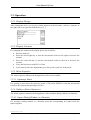
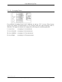
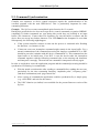
3.3. Operation
3.3.1. Display Design
After starting the device you can see a menu sequence at the left and a „soft-key“-sequence at
the right side (to be operated with the keys (7) ).
3.3.2. Display Contrast
For changing the contrast of the display please act as follows:
•
•
•
Press the help-key
Press the cursor-right-key or turn the incremental switch to the right to increase the
contrast
Press the cursor-left-key or turn the incremental switch to the left to decrease the
contrast.
Leave the help-menu with ESC or Enter
•
If you want to store the adjustments go to Set-up, Save and Yes in the menu.
•
3.3.3. Menu Sequence
The menu sequence indicates the designations of the menu available.
3.3.3.1. Opening a Menu
For opening a menu move the cursor by means of UP and/or DOWN or with the incremental
switch to the requested menu and press Enter.
3.3.4. Softkeys (Status Sequence)
The status sequence indicates the designations of the available dialog windows or functions.
3.3.4.1. Open a Dialog Window or a Function
For opening a dialog window or a function, press the corresponding key right beside the
status sequence.
16.07.2013 E_SYC_V6_11.doc
Spitzenberger & Spies GmbH & Co. KG
Page 6
User Manual SyCore
3.3.5. Dialog Window
The dialog window indicates the available input panels and switch panels.
3.3.5.1. Input Lines
At the input panel for example a voltage value can be adjusted.
•
•
•
•
•
•
•
By means of the numeric keys you can input a value.
With +/- you can change the sign of a value.
With Right and Left you can move the cursor in the input panel.
With Del you can delete a figure above the cursor.
With Esc the original value will be indicated again.
With Enter the value will be accepted.
With the incremental switch you can change a value incrementally (+)
or decrementally (-).
3.3.5.2. Radio Buttons
With the radio buttons a switch can be selected.
•
•
•
•
•
With Right and Left you can move the cursor.
With the numeric keys 1 ... 9 the buttons can be selected directly; 1 is the first button,
2 is the second button et cetera .
With Esc the original switch will be indicated again.
With Enter the switch will be accepted.
With the incremental switch you can move the cursor.
16.07.2013 E_SYC_V6_11.doc
Spitzenberger & Spies GmbH & Co. KG
Page 7
User Manual SyCore
3.3.6. Description of the Keys
3.3.6.1. Edit Keys
indicates the origin value or leaves the menu and the dialog window
deletes figures above the cursor
changes signs of a number
accepts input lines, radio buttons and dialog window
Esc
Del
+/Enter
3.3.6.2. Cursor Keys
▲
▼
►
◄
Up
Down
Right
Left
changes selection between input lines, radio buttons and menu points
changes selection between input lines, radio buttons and menu points
changes selection of radio buttons
changes selection of radio buttons
3.3.6.3. Digital Keys
0 ... 9
•
Decimal point
3.3.6.4. Function Keys
Output
Func1
Func2
Func3
Func4
Local
Output on/off
Impedance on/off
Inrush current source on/off
not fitted
Status indication current limit via LED (push-button without function)
Local / remote control
16.07.2013 E_SYC_V6_11.doc
Spitzenberger & Spies GmbH & Co. KG
Page 8
User Manual SyCore
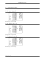
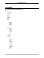
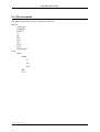
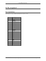
3.3.7. Menu Tree
Oscillator
Amplitude/Angle
Frequency
A/AF-Pulse
F-Pulse
Trig/Sync/Add/Mult
Function
Memory
Measurement
Rms
Frequency
Oscilloscope
Control
Amplifier
Amplifier Enh
Parallel Conn
Impedance
Current Limit
R-Load
Macros
Run
Record
List
Load
Save
Delete
Setup
Interface
Info
Use
16.07.2013 E_SYC_V6_11.doc
Spitzenberger & Spies GmbH & Co. KG
Page 9
User Manual SyCore
4. Oscillators
Several arbitrary waveform generators are available. For the utilisation of the all functions of
these generator, a certain basic knowledge on the way of function is required. If you want to
use only the standard functions for the time being, you can overleap the following section
"Function Diagram".
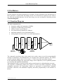
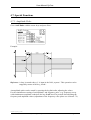
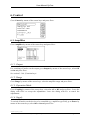
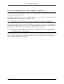
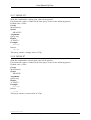
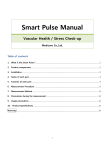
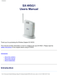
4.1. Function Diagram
The main components are:
Waveform Memory
Address Counter
Clock
Generator
Frequency
Adjustment
Amplitude Multiplier
frequency-stable clock generator (10MHz)
frequency conditioning (17bit divider)
address counter (up to 1Mbyte)
waveform memory (RAM up to 1Mbyte)
amplitude multiplier (for each channel/phase)
analog/digital converter (DAC; for each channel/phase)
Frequency Conditioning
•
•
•
•
•
•
D/A Converter
Analog
Signal
Amplitude
Adjustment
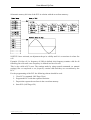
The requested waveforms (sine, delta, square-wave, pulse, ramp or even free-programmable
mixings of harmonics and subharmonics) are stored in the waveform memory. An address
counter reads the digital values (16 bit values = ±32767) out of this waveform memory.
In the amplitude multiplier the requested voltage will be adjusted (16 bit 4-quadrant product
of waveform and amplitude adjustment).
This multiplied value is converted to the analog control signal via a digital/analog converter.
The frequency conditioning defines the speed to read the waveform (frequency). During
multiphase operation, the single-phase signals are generated in time-division multiplex
procedure. Therefore, the maximum frequency decreases proportionally to the number of
phases.
16.07.2013 E_SYC_V6_11.doc
Spitzenberger & Spies GmbH & Co. KG
Page 10
User Manual SyCore
4.2. Generation of Low-Frequency AC Voltages
When generating low-frequency AC and DC voltages high-quality waveform is more
important than the output speed. Therefore we recommend to select higher memory-depths
(1k, 4k or 16k) to achieve a better harmonic distortion when using power engery frequencies
(16 2/3Hz, 50Hz, 60Hz, 400Hz).
When using multi-phase systems the phase number has to be adjusted to a value >1. Thus, the
maximum possible output frequency is reduced but then again the frequency resolution is
increased (see table in section 4.7.4).
4.3. Generation of High-Frequency AC Voltages
When generating high-frequency AC voltages (kHz-range, e.g. EV amplifiers) high output
speed is important while the waveform quality is inferior. A higher harmonic distortion is
secondary because the amplifier can´t transmit high-frequent components of the signal.
Therefore, you should select lower memory depth for the generation of higher frequencies
(256, 1k).
For additional increasing of the maximum output frequency several periods of one signal can
be written into the 256-point memory. Furthermore the phase number of the oscillator should
be set to 1 (if possible). Please see section 4.7.4
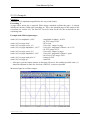
4.4. Basic Adjustment
The amplifier is set to the following basic adjustments:
Oscillator:
•
Amplitude:
0% for each phase
•
Phase angle:
0° phase 1; 120° phase 2; 240° phase 3; 0° phase 4
(only at 4-phase version, at less phases reduced corresponding)
•
Frequency:
50Hz
•
Trigger:
0°
•
Synchronisation: Out
•
Function:
Sine for each phase
•
Memory depth:
1k (1024 points)
Oscillator type
Memory depth
Start address Phase 1
Start address Phase 2
Start address Phase 3
Start address Phase 4
1Kbyte
1024
0
0
0
0
64Kbyte
1024
0 (Page 1)
16384 (Page 17)
32768 (Page 33)
49152 (Page 50)
1024Kbyte
1024
0 (Page 1)
262144 (Page 257)
524288 (Page 513)
786432 (Page 769)
16.07.2013 E_SYC_V6_11.doc
Spitzenberger & Spies GmbH & Co. KG
Page 11
User Manual SyCore
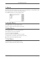
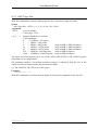
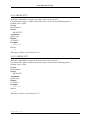
4.5. Basic Functions
Open the menu Oscillator. The display shows:
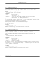
4.5.1. Amplitude and Phase Angle
Select amplitude/angle. The amplitude menu appears:
4.5.1.1. Amplitude
Go to Amplitude with the cursor keys, set the amplitude and press Enter.
The amplitude is set at the adjusted trigger angle. The trigger angle refers to a virtual phase 0.
4.5.1.2. Angle
Go to Angle with the cursor keys, set the angle and press Enter.
The phase angle is set to the adjusted trigger angle. The trigger angle refers to a virtual
phase 0.
4.5.1.3. + Angle
Go to +Angle with the cursor keys, set the angle and press Enter.
This value is added to angles of the phases 1 – 4.
If e.g. 90 is set the following angles result:
P1=0+90, P2=120+90, P3=240+90.
16.07.2013 E_SYC_V6_11.doc
Spitzenberger & Spies GmbH & Co. KG
Page 12
User Manual SyCore
4.5.1.4. Synchronized Amplitude Phases
Go to Sync Phases with the cursor keys, set the phases and press Enter.
The value Sync Phases indicates which amplitude phases are synchronized.
Adjust e.g. 123 to synchronize amplitude 1+2+3.
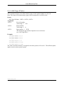
4.5.2. Frequency Adjustment
Select frequency. The frequency menu appears:
Go to Frequency with the cursor key, set the frequency and press Enter.
The minimum and maximum possible frequency and the resolution are linked to the adjusted
memory depth and phase number. Closer information see section 4.7.4.
16.07.2013 E_SYC_V6_11.doc
Spitzenberger & Spies GmbH & Co. KG
Page 13
User Manual SyCore
4.5.3. Trigger/Synchronous/Adder/Multiplier
Go to Trig/Sync with the cursor keys and press Enter.
4.5.3.1. Trigger
Go to trigger with the cursor keys, feed the trigger angle and press Enter.
The amplitude, the phase angle as well as the amplitude pulse are set at the adjusted trigger
angle. The trigger angle refers to an internal virtual phase 0.
4.5.3.2. Synchronizing
Go to synchron with the cursor keys, select in, out or line and press Enter.
In:
the oscillator is synchronised with the synchronizing pulse of the other internal
oscillator.
Out: the oscillator sets the synchronizing pulse for the other internal oscillator.
Line: the oscillator is synchronised with line signal (only at option “mains synchronous”). If
several oscillators are available all oscillators are set to Line in this operation mode.
Line shall only be adjusted when the adjusted frequency of the oscillator corresponds
to the mains frequency because the correction angle at 50Hz and/or 60Hz refers
always to the oscillator frequency.
Devices with 2 oscillators: When one oscillator is synchronized to the mains
frequency and the second oscillator adds a signal with a higher frequency the right
correction angle is only used when the oscillator synchronized to the mains frequency
is adjusted to Line.
When the mains synchronisation is switched on solely the tests EN 61000-32/3/11/12 can be performed.
Reference: Never set all oscillators to In because this may cause undefined operation modes.
When switching off the operation mode Line, firstly Out has to be set.
Afterwards one of the oscillators can be set to In again.
16.07.2013 E_SYC_V6_11.doc
Spitzenberger & Spies GmbH & Co. KG
Page 14
User Manual SyCore
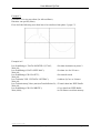
4.5.3.3. Card Selection
Go to Ph1, Ph2 oder Ph3 with the cursor keys, select Add oder Mult and press Enter. You
can select the phases 1...3 variously.
Add:
SyCore with 1 Oscillator
SyCore with 2 Oscillators
The voltages of referring phase of the first The voltages of the referring phases of
oscillator and the external control voltage
both oscillators ( 1 and 2 ) are added.
(sockets “ext. Input“) are added.
Mult:
SyCore with 1 Oscillator
SyCore with 2 Oscillators
The voltages of the referring phase of the The voltages of the referring phase of
first oscillator and the external control both oscillators ( 1 and 2 ) are multiplied.
voltage (sockets “ext. Input“) are
multiplied.
16.07.2013 E_SYC_V6_11.doc
Spitzenberger & Spies GmbH & Co. KG
Page 15
User Manual SyCore
4.6. Flicker Simulation (in Connection with Opt. „Multiplier“)
The following flicker simulations can be only conducted when the option „Multiplier“ is
available“.
For the direct generation of sinusoidal or rectangular voltage fluctuations (flicker simulation)
for simplification purposes a DC-voltage should additionally be added to the multiplicand.
Example:
Simulation of a sinusoidal flicker, 8.8Hz, 2% of nominal voltage. Please act as follows:
1. Switch on the multiplier:
Menu „Oscillator“ - submenu „Trig/Sync/Add/Mult“
For phase 1 select the adjustment „Mult“ in „Ph1“.
2. Select oscillator card 2
3. Set 230V amplitude at phase 1
4. Set 50Hz frequency
5. Select oscillator card 1
6. Change the waveform of phase 4 to DC
7. Set the amplitude of phase 4 to the maximum value (381.83V in range 270V).
8. Set the amplitude of phase 1 to 7,64V (381.83 * 2/100).
9. Set 8.8Hz frequency
Item 2…4 Adjustment of the nominal voltage.
Item 6…9: Addition of a DC voltage with 100% amplitude (corresponds to factor 1) to the
adjusted voltage change (item 8). Thus, the requested voltage fluctuation can be
defined directly in the amplitude adjustment.
Reference: When using integer values (item 9) of the basic frequency (item 4) we
recommend to enable the synchronisation of the oscillators in order to avoid
disturbances by beats.
16.07.2013 E_SYC_V6_11.doc
Spitzenberger & Spies GmbH & Co. KG
Page 16
User Manual SyCore
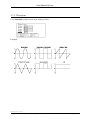
4.7. Special Functions
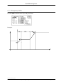
4.7.1. Amplitude Pulse
Go to A/AF-Pulse with the cursor keys and press Enter.
Example:
Reference: A loop is started when „0“ is input in the field „repeats“. This operation can be
stopped by means of the key „break“.
An amplitude pulse can be started by pressing the key St A after adjusting the values.
For the simultaneous starting of an amplitude- and frequency pulse (e.g. frequency sweep
with simultaneous amplitude reduction) the key St AF has to be pressed after adjusting the
frequency and amplitude values (adjustment of the frequency value please see section 4.7.2).
16.07.2013 E_SYC_V6_11.doc
Spitzenberger & Spies GmbH & Co. KG
Page 17
User Manual SyCore
4.7.2. Frequency Pulse
Go to F-Pulse with the cursor keys and press Enter.
Example:
16.07.2013 E_SYC_V6_11.doc
Spitzenberger & Spies GmbH & Co. KG
Page 18
User Manual SyCore
4.7.3. Waveform
Go to Function with the cursor keys and press Enter.
Example:
16.07.2013 E_SYC_V6_11.doc
Spitzenberger & Spies GmbH & Co. KG
Page 19
User Manual SyCore
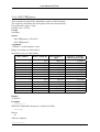
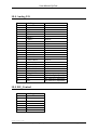
4.7.4. Memory Depth
Go to Memory with the cursor keys and press Enter. Here you can set the number of the
digital resolution points per period.
Go to Periods with the cursor keys and press Enter. The frequency can be increased the
multiple of the set period with this function.
Example: When setting 2 periods the maximum frequency doubles i.e. two periods are
generated in the selected memory range (e.g. 1kB). The doubling of the signal
frequency with the same output frequency is calculated automatically in the
manual frequency input. Thus, subsequent frequency specifications result in the
correct signal output frequency.
The lower the memory depth, the higher the maximum frequency; the lower the frequency
resolution, the higher harmonic distortion and minimum frequency. A good compromise are
the adjustments 1kB or 4kB. The number of the digital resolution points per period is equal to
the memory depth. For detailed data please refer to the following table.
Phase number
Memory depth [B]
1
1
1
1
2
2
2
2
4
4
4
4
1
1
256
1024
4096
16384
256
1024
4096
16384
256
1024
4096
16384
256 (2 Periods)
256 (4 Periods)
Max-Frequency
[Hz]
39,062.50
9,765.62
2,441.40
610.35
19,531.25
4,882.81
1,220.70
305.18
9,765.62
2,441.40
610.35
152.59
78,131.00
156,262.00
Frequency resolution
= Min.-Frequency [Hz]
0.298,023
0.074,506
0.018,626
0.004,657
0.149,012
0.037,253
0.009,313
0.002,328
0.074,506
0.018,626
0.004,657
0.001,164
0.596,046
1.192,092
Attention: Function, frequency and voltage have to be readjusted after every change of
the memory depth.
16.07.2013 E_SYC_V6_11.doc
Spitzenberger & Spies GmbH & Co. KG
Page 20
User Manual SyCore
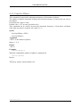
4.7.5. Angle Resolution
Attention: The lower the memory depth, the lower the angle resolution. The higher the
memory depth, the higher the angle resolution. For detailed data please refer to
the following table.
Depth
256
1,024
4,096
16,384
Depth =
Ares =
Ares
1.406,250
0.351,562
0.087,891
0.021,973
memory depth
angle resolution
16.07.2013 E_SYC_V6_11.doc
Spitzenberger & Spies GmbH & Co. KG
Page 21
User Manual SyCore
5. Measurement
Open the menu Measurement (if available). The display indicates:
Reference: The description of the soft keys can be found in the sections 3.3.1 and 3.3.4.
5.1. RMS
Go to RMS with the cursor keys and press Enter.
5.1.1. Voltage and Current Measurement
5.1.1.1. r.m.s. - Value Measurement (U/I)
AC-Mode
The r.m.s.-value can be determined as follows:
U=
1T
∫ u(t ) 2 dt
T0
I=
1T
∫ i(t ) 2 dt
T0
The direct component is decoupled via a capacitor.
16.07.2013 E_SYC_V6_11.doc
Spitzenberger & Spies GmbH & Co. KG
Page 22
User Manual SyCore
DC-Mode
The direct component for voltage and current is determined as follows:
1T
U = ∫ u(t )dt
T0
1T
I = ∫ i (t )dt
T0
AC/DC-mode
During the AC+DC mode the direct component of a signal won’t be decoupled. The voltage
and current value is determined like during the AC-mode.
16.07.2013 E_SYC_V6_11.doc
Spitzenberger & Spies GmbH & Co. KG
Page 23
User Manual SyCore
5.1.1.2. Peak Value (U/I) and Crest-Factor Measurement (CF U/CF I)
Peak mode
The peak value for voltage and current will be measured in the peak mode.
The crest factor for voltage and current is determined as follows:
CFU =
US
U
CFI =
IS
I
At the peak-value measurement the direct component of the measuring signal is not
decoupled.
5.1.1.3. Offset Compensation
The DC offset of the measuring system will be compensated by this function. For this, the
measuring inputs and/or the measuring lines, which go to the measuring object, will have to
be short-circuited. After pressing the key ”S4” (0=off) a window with the DC offset of the
measuring system appears for approx. 2s. The offset compensation is active as soon as the
window goes out and the position of the key ”S4” switches to ”0=on”. During repeated
operation of the key ”S4” the offset compensation switches off (0=off).
With the key ”S5” (view) you have the capability to indicate the finally-measured DC offset
via a window which is faded in for approx. 2s.
16.07.2013 E_SYC_V6_11.doc
Spitzenberger & Spies GmbH & Co. KG
Page 24
User Manual SyCore
5.1.1.4. Averaging Factor
Four different averaging factors can be adjusted via the key ”S3” (?-Accu). These factors
specify the number of measurements to be averaged before the right measuring value is
indicated. The higher the adjusted averaging factor, the longer the measuring duration.
L-Accu (Low):
averaging via 1 measurement
N-Accu (Normal): averaging via 8 measurements
M-Accu (Middle): averaging via 32 measurements
H-Accu (High):
averaging via 128 measurements
16.07.2013 E_SYC_V6_11.doc
Spitzenberger & Spies GmbH & Co. KG
Page 25
User Manual SyCore
5.1.2. Power Measurement
5.1.2.1. Active Power (P)
Press the key „S2“ to select P.
5.1.2.2. Apparent Power (S)
Press the key „S2“ to select S.
5.1.2.3. Reactive Power (Q)
Press the key „S2“ to select Q.
16.07.2013 E_SYC_V6_11.doc
Spitzenberger & Spies GmbH & Co. KG
Page 26
User Manual SyCore
Power Factor (PF)
16.07.2013 E_SYC_V6_11.doc
Spitzenberger & Spies GmbH & Co. KG
Page 27
User Manual SyCore
5.2. Frequency Measurement
Go to RMS with the cursor keys and press Enter.
Four different averaging factors can be adjusted via the key ”S1” (?-Accu). These factors
specify the number of measurements to be averaged before the right measuring value is
indicated. The higher the adjusted averaging factor, the longer the measuring duration.
L-Accu (Low):
averaging one measurement
N-Accu (Normal): averaging eight measurements
M-Accu (Middle): averaging 32 measurements
H-Accu (High):
averaging 128 measurements
16.07.2013 E_SYC_V6_11.doc
Spitzenberger & Spies GmbH & Co. KG
Page 28
User Manual SyCore
5.3. Oscilloscope
Open the menu oscilloscope. The following is displayed:
5.3.1. Channel Adjustment
5.3.1.1. Channel Selection and Trigger Adjustment
Press the button ”S1” to select channel 1 or channel 2 or to get to the trigger adjustment.
(CH1, CH2 or TRIG).
All adjustments ”S2” to ”S7” refer to the selected channel.
5.3.1.2. Signal Representation
Press the button ”S2” to switch on and/or off the signal representation (ON or OFF).
5.3.1.3. Phase Selection
Press the button ”S3” to select the phase to measure ( P1, P2 or P3 ).
5.3.1.4. Amplitude Adjustment
Press the button ”S5” and/or ”S6” to adjust the amplitude of the signal representation
( ∆AMP or ∇AMP ).
16.07.2013 E_SYC_V6_11.doc
Spitzenberger & Spies GmbH & Co. KG
Page 29
User Manual SyCore
5.3.2. Trigger Adjustment
Press the button ”S1” to select channel 1 or channel 2 or to get to the trigger adjustment.
(CH1, CH2 or TRIG).
All adjustments ”S2” to ”S7” refer to the trigger adjustment.
5.3.2.1. Edge Selection
Press the button ”S2” to select the edge and the channel to trigger on. (CH1, -CH1, +CH2 or
-CH2).
5.3.2.2. Trigger Level
Press the button ”S5” and/or ”S6” to adjust the trigger level to trigger on ( ∆LEV or ∇LEV ).
5.3.2.3. Time Base
Press the button ”S7” and/or ”S8” to adjust the time base ( ∆TB or ∇TB ).
16.07.2013 E_SYC_V6_11.doc
Spitzenberger & Spies GmbH & Co. KG
Page 30
User Manual SyCore
6. Control
Go to Control by means of the cursor keys and press Enter.
6.1. Amplifier
Go to Amplifier by means of the cursor keys and press Enter.
6.1.1. Output
For switching off and/or on the output go to Output by means of the cursor keys, select Off
or On and press Enter.
See section 3.3.6.4 „Function keys“.
6.1.2. Range
Go to Range by means of the cursor keys, select the amplifier range and press Enter.
6.1.3. Operation Mode
Go to Coupling by means of the cursor keys, select the AC or DC and press Enter. Leave the
dialog with Enter to accept the adjustments. Leave the dialog with Esc to cancel the
adjustments.
6.1.4. Supply
To switch off and/or on the device to be controlled (e.g. amplifier type PAS) go to Power by
means of the cursor keys, select Off or On and press Enter.
16.07.2013 E_SYC_V6_11.doc
Spitzenberger & Spies GmbH & Co. KG
Page 31
User Manual SyCore
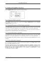
6.2. Enhanced Amplifier Functions
Go to Amplifier Enh with the cursor keys and press Enter.
6.2.1. Operation Mode (optional)
Go to Mode with the cursor keys, select V for Voltage Amplification or A for Current
Amplification and press Enter.
6.2.2. Internal Resistance at Pulse Output (optional)
Go to RI by pulse with the cursor keys, select OFF or ON and press Enter. Leave the dialog
with Enter to accept the adjustments. Leave the dialog with Esc to reject the adjustments.
At the output of the amplitude pulse (A/AF-Pulse) or of the PCL the internal resistance is
switched for the adjusted duration (A/AF-Pulse Duration).
6.2.3. Internal Resistance (optional)
Go to RI with the cursor keys, adjust the requested value and press Enter. Leave the dialog
with Enter to accept the adjustments. Leave the dialog with Esc to reject the adjustments.
RI is the value of the internal resistance which is switched when the amplitude pulse or PCL
is output.
6.2.4. Pulse Operation (optional)
For switching on/off the pulse operation (switch power supply), go to Pulse with the cursor
keys, select Off or On and press Enter.
The pulse operation has to be reset manually. Although the amplifier switches off the
pulse operation automatically after approximately two seconds voltage distortions are
possible. In any case a waiting period (a few seconds) is recommended to avoid
overheating of the power supply.
16.07.2013 E_SYC_V6_11.doc
Spitzenberger & Spies GmbH & Co. KG
Page 32
User Manual SyCore
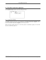
6.3. Parallel Connection (optional)
Go to Parallel Conn with the cursor keys and press Enter.
6.3.1. Operation Mode
Go to Par, with the cursor keys, select Off, L12 for Parallel Connection Amplifier 1-2 or
L123 for Parallel Connection Amplifier 1-2-3 and press Enter.
When selecting parallel mode L12 or L123 the system is controlled via phase L1. The EUT
has to be connected to phase L1.
16.07.2013 E_SYC_V6_11.doc
Spitzenberger & Spies GmbH & Co. KG
Page 33
User Manual SyCore
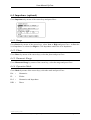
6.4. Impedance (optional)
Go to Impedance by means of the cursor keys and press Enter.
6.4.1. Range
Go to Device by means of the cursor keys, select Low or High and press Enter. At Low the
16A-Impedance is selected; at High the 32A-Impedance and/or the 63A-Impedance.
6.4.2. Phase
Go to Phase by means of the cursor keys, select the phase and press Enter.
6.4.3. Harmonic Range
Go to Harmonic Range by means of the cursor key, select the range and press Enter.
6.4.4. Operation Mode
Go to Mode by means of the cursor keys, select the mode and press Enter.
HA =
Harmonics
FL
Flicker
=
H+I =
Harmonics and Impedance
DIR =
Direct
16.07.2013 E_SYC_V6_11.doc
Spitzenberger & Spies GmbH & Co. KG
Page 34
User Manual SyCore
6.5. Current Limitation (optional)
Go to Current Limitation by means of the cursor keys and press Enter.
6.5.1. Switching on
For switching off and/or on the current limitation go to Control by means of the cursor keys,
select Off or On and press Enter.
6.5.2. Operation Mode
Go to Mode by means of the cursor keys, select Limit (current limitation) or Switch off
(switching off) and press Enter.
6.5.3. Current Value
To adjust the limitation value and/or switching-off value of the current limitation go to
Current by means of the cursor keys, feed the current value and press Enter.
6.5.4. Status
The status is indicated by the 2 LED’s of the Func 4 button.
The LED’s mean:
LED off
=
no limit/switch off
LED on
=
limit
LED off+on =
switch off
6.5.5. Synchronized Amplitude Phases
Go to Sync Phases with the cursor keys, set the phases and press Enter.
The value Sync Phases indicates which amplitude phases are synchronized.
Adjust e.g. 123 to synchronize amplitude 1+2+3.
16.07.2013 E_SYC_V6_11.doc
Spitzenberger & Spies GmbH & Co. KG
Page 35
User Manual SyCore
Description:
Operating mode Limit
When exceeding the adjusted current value, the output voltage is reduced to 0V and then
increased until the pre-set current flows. The status LED (LED on Func 4-push-button)
indicates the limiting.
Operating mode Switch Off
When exceeding the adjusted current value, the output is switched off. The status LED’s
(LED off+on Func 4-pushbutton) indicate the switching-off.
Reference:
The current control is working with r.m.s.-values.
The reaction time is approx. 40ms.
6.6. Resistor Load (optional)
Go to R-Load with the cursor keys and press Enter.
Select the requested load. The values are accepted by pressing the Enter key.
The specification of the power refers to 230V sink mode. When using other voltages the
power has to be converted accordingly. Even though the load can be used in normal operation
it is actually designed for the sink mode to increase the consumable power.
16.07.2013 E_SYC_V6_11.doc
Spitzenberger & Spies GmbH & Co. KG
Page 36
User Manual SyCore
6.7. Amplifier Selection (optional)
Go to Use with the cursor keys and press Enter. The following is displayed:
6.7.1. Oscillator Card Selection
Go to Osc with the cursor keys, select 1 or 2 and press Enter (if available).
All following changes in the oscillator menu refer to the selected oscillator card.
6.7.2. Measurement Card Selection
Go to Meas with the cursor keys, select 1 or 2 and press Enter (if available).
All following changes in the measurement menu refer to the selected measurement card.
6.7.3. Amplifier Selection
Go to Amp with the cursor keys, select 1, 2, 3, 4 or all and press Enter (if available).
All following changes in the amplifier control dialog refer to the selected amplifier.
16.07.2013 E_SYC_V6_11.doc
Spitzenberger & Spies GmbH & Co. KG
Page 37
User Manual SyCore
6.8. Safe Communication with Amplifier (optional)
This function can not be switched via menu. It is enabled by the manufacturer when the used
amplifier supports the protocol.
Background: advanced safety, the amplifier/amplifiers are switched off safely when the
communication between SyCore and amplifier fails.
6.8.1. Reaction of the SyCore to incorrect Response from the Amplifier
When the adjustment of one or several amplifier fails three times in a row all amplifiers are
switched off by the SyCore (Power off). The display indicates the message: „Error RS485 –
Switched Power Off“. The message disappears when any key is pressed.
6.8.2. Reaction of the Amplifier to incorrect Checksum of the Adjustmentor Measurement Commands
When an amplifier receives an incorrect command (false checksum) the display indicates an
error message. Additionally, both LEDs (beside the output push-button) are illuminated as
long as the fault applies at the amplifier.
16.07.2013 E_SYC_V6_11.doc
Spitzenberger & Spies GmbH & Co. KG
Page 38
User Manual SyCore
7. Macros
By means of the macro functions key strokes can be stored (Record), executed (Run), listed
(List), loaded (Load), saved (Save) und deleted (Delete).
Go to macros with the cursor-keys and press Enter.
7.1. Execute Macros
Go to run with the cursor keys and press Enter.
Now the recorded or stored key strokes are executed.
7.2. Store Macros
Go to record with the cursor keys and press Enter.
In the right-down corner rec is indicated.
You are in the macro record mode.
Now the key strokes (except the soft keys) are stored.
To end the macro record-mode, please press the Func4-key.
Rec will be deleted in the right-down corner.
7.3. List Macros
Go to list with the cursor keys and press Enter.
Now the recorded or stored key strokes are listed.
16.07.2013 E_SYC_V6_11.doc
Spitzenberger & Spies GmbH & Co. KG
Page 39
User Manual SyCore
7.4. Load Macros
Go to Load with the cursor keys and press Enter.
Feed the number of the macro (0 ... 9), where the key stroke is are stored. Now the loaded
macro can be executed with Run.
7.5. Save Macros
Go to Save with the cursor keys and press Enter.
Feed the number of the macro (0 ... 9), where the key stroke is to be stored. The macro No 0
(Start-Macro) is loaded and executed when starting the device.
Now the key strokes are saved under the fed number of the macro (0 ... 9).
7.6. Overwrite Macros
Reference: Macros can only be overwritten and not deleted.
Macros can be overwritten as described in section 7.5 „Save Macros“. To delete a “StartMacro” (No 0) act as follows:
1. Go to Macros-> Record.
2. Press the key Func4 to finish the macro recording.
3. Go to Macros->Save. Feed the number 0 (Start-Macro).
16.07.2013 E_SYC_V6_11.doc
Spitzenberger & Spies GmbH & Co. KG
Page 40
User Manual SyCore
Example:
At switching-on the device the following fundamental state of the oscillator has to be
executed: the angles of the phases 1 ... 3 of the oscillator have to be at 0°.
Please act as follows:
4. Go to Macros->Record. Now all key strokes are recorded.
5. Go to Oscillator->Amplitude/Angle. Feed an angle (phase 1 ... 3) of 0°.
6. Press the Func4-key to end the macro record.
7. Go to Macros->Save. Feed the number 0 (Start-Macro). Now the angles of the
phases 1 ... 3 are set to 0° when switching on the device.
16.07.2013 E_SYC_V6_11.doc
Spitzenberger & Spies GmbH & Co. KG
Page 41
User Manual SyCore
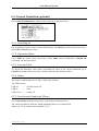
8. Set-up
Open the menu Setup. The display shows:
8.1. Adjustment of the Interface address
Go to Interface with the cursor keys and press Enter.
Go to Address with the cursor keys, feed the requested IEEE-Interface address and press
Enter.
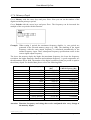
8.2. Info
Go to Info with the cursor keys and press Enter.
This window displays the following information:
-
Copyright and name of the company
-
Version number of the firmware
-
Number of the connected amplifiers and control mode
-
Installed oscillator cards
-
Installed and/or connected measurement cards
-
Configuration Bytes
16.07.2013 E_SYC_V6_11.doc
Spitzenberger & Spies GmbH & Co. KG
Page 42
User Manual SyCore
9. IEEE488 Interface
The device can be controlled via IEEE488 interface. A large number of commands and
queries are available.
This section describes the installation of the IEEE module. IEEE488 is a parallel 8 bit
communication standard that enables the communication of the device with an external
controller e.g. a computer or a terminal.
To each device a single IEEE address is assigned. The application of one address for two
devices is not allowed.
The IEEE address is factory-set to 6.
If required, the IEEE address can be changed in the configuration menu (section 8.1).
Command sequences have to be closed with the final character LF (LINE FEED,
HEX: 0A)+EOI-line.
9.1. Command Syntax
The basic structure of a command is made up of the elements command, space and argument.
Example: AMP:Output 1
AMP:Output is the command, 1 is the argument and between command and argument there is
always a space.
The capital letters of the command must be input, the lower case letters are optional.
If several commands have to be transferred in one transfer sequence the commands have to be
separated with a semicolon.
Example: AMP:Mode 1;AMP:Output 1
The basic structure of a query is made up of a command and a question mark (no space
between command and question mark).
Example: MEAS:Voltage?
The return value is available for transmission in an output buffer.
In section 9.3 all control commands and queries are listed.
The following notation is used for the description of the command syntax:
Symbol
<>
{}
[]
|
... .
Meaning
Defined element
Group, one element is required
Optional, can be omitted
Exclusive Or
Previous element(s) may be repeated
Example:
AMP:Output {0 | 1}
16.07.2013 E_SYC_V6_11.doc
Spitzenberger & Spies GmbH & Co. KG
Page 43
User Manual SyCore
9.2. Command Synchronization
Complex test sequences or device control sequences require the synchronization of the
executed program with the used IEEE-device. This is particularly important for timeconsuming functions.
Example: The SyCore executes an amplitude pulse function for 12 seconds.
During this period the device does not accept device control commands (exception: BREAKcommand). If further commands are sent during this period they are buffered in an input
buffer (256 characters). If more than 256 characters are sent the buffer overflows and the
device does not accept any further character. The LED Func3 at the frontpanel is set to On.
Subsequently, the following might happen:
•
If the system controller releases no time-out the process is continued after finishing
the function – no character is lost.
•
If time-out occurs an incomplete command might remain in the input buffer. For a
normal continuation of the command processing the interface command DCL or SDC
should be sent (don´t mistake with the device command DCL). This command sets the
input buffer to its initial state. If no DCL is sent the device takes the incomplete
command together with the following command (due to the missing end character)
and interprets it wrongly. The next but one command is interpreted correctly again.
In order to avoid these errors the application program and the command processing should be
synchronized. Following is recommended:
•
Wait the stated execution time after sending a command before sending the next one,
particularly for the time consuming functions “amplitude pulse”, frequency pulse”
(and their combinations) and “page control list”.
•
After a group of commands the application could be synchronized by a simple query
(e.g.: send *IDN? and wait for the return).
•
The *OPC-function (or similar) is not available for the present firmware version of the
SyCore.
16.07.2013 E_SYC_V6_11.doc
Spitzenberger & Spies GmbH & Co. KG
Page 44
User Manual SyCore
9.3. List of Commands
The SyCore interface is structured in several sub-systems working more or less independent
from each other. Following the sub-systems are described more closely.
Oscillator
Description
Active Oscillator card
Adder/Multiplier
Amplitude
Amplitude acceptance
Amplitude- and frequency pulse start
Amplitude pulse delay time
Amplitude pulse durationt
Amplitude pulse end-amplitude
Amplitude pulse fall time
Amplitude pulse pulse amplitude
Amplitude pulse repeats
Amplitude pulse rise time
Amplitude pulse start
Amplitudenpuls start amplitude
Frequency
Frequency pulse delay time
Frequency pulse duration
Frequency pulse end frequency
Frequency pulse fall time
Frequency pulse pulse frequency
Frequency pulse repeats
Frequency pulse rise time
Frequency pulse start
Frequency pulse start frequency
Phase angle
Phases
Synchronisation
Trigger angle
Command
OSC:Use
OSC:ADDMult
OSC:AMPlitude
OSC:AMPlitude:ACCept
OSC:AFPuls:GO
OSC:APuls:DElayt
OSC:APuls:DURAT
OSC:APuls:END
OSC:APuls:FALLT
OSC:APuls:PULS
OSC:APuls:REpeats
OSC:APuls:RISET
OSC:APuls:GO
OSC:APuls:START
OSC:FREQuency
OSC:FPuls:DElayt
OSC:FPuls:DURAT
OSC:FPuls:END
OSC:FPuls:FALLT
OSC:FPuls:PULS
OSC:FPuls:REpeats
OSC:FPuls:RISET
OSC:FPuls:GO
OSC:FPuls:START
OSC:ANGle
Conf:Osc:PHases
OSC:Sync
OSC:TRigger
Section
9.4.8
9.4.7
9.4.1
9.4.2
9.4.19
9.4.17
9.4.14
9.4.12
9.4.15
9.4.11
9.4.16
9.4.13
9.4.18
9.4.10
9.4.4
9.4.27
9.4.24
9.4.22
9.4.25
9.4.21
9.4.26
9.4.23
9.4.28
9.4.20
9.4.3
9.4.9
9.4.6
9.4.5
16.07.2013 E_SYC_V6_11.doc
Spitzenberger & Spies GmbH & Co. KG
Page 45
User Manual SyCore
Page Control List
Description
Enable pulse operation
Increase of the maximum frequency range
List cell cycles
List cell paramter
List cell run after “BREAK”-command
PCL clear
PCL interrupt
PCL start
PCL start by trigger
Waveform frequency
Waveform memory amplitude
Waveform memory cycles
Waveform memory number
Waveform memory phase angle
Waveform memory size
Waveform memory trigger angle
Waveform (adjust/query)
Memory depth (adjust/query)
Command
Section
OSC:Page:PULS
9.5.8
OSC:Page:PEriods
9.5.17
OSC:Page:TOtalcycle 9.5.10
s
OSC:Page:PArameter
9.5.16
OSC:Page:STopnumer 9.5.11
OSC:Page:CLear
9.5.15
OSC:BREAK
9.5.14
OSC:Page:GO
9.5.12
OSC:Page:GO
9.5.13
OSC:Page:FRequency
9.5.4
OSC:Page:AMplitude
9.5.7
OSC:Page:CYcles
9.5.1
OSC:Page:NUmber
9.5.5
OSC:Page:ANgle
9.5.6
OSC:Page:SIize
9.5.2
OSC:Page:TRigger
9.5.3
OSC:Page:FUnction
9.5.9
OSC:PAge:MEMory
9.5.18
Measurement
Description
Active Measurement card
Active power (query)
Apparent power (query)
Current crest factor (query)
Current peak value (query)
Current value (query)
Frequency of the voltage (query)
Measurement mode switching
Measuring phase switching
Power factor (query)
Reactive power (query)
Voltage crest factor (query)
Voltage peak value (query)
Voltage value (query)
Command
Meas:Use
MEAS:POWer?
MEAS:S?
MEAS:CFI?
MEAS:IP?
MEAS:CURRent?
MEAS:FREQuency?
Conf:Meas:Mode
Conf:Meas:PH
MEAS:PF?
MEAS:Q?
MEAS:CFU?
MEAS:UP?
MEAS:VOLTage?
Section
9.6.14
9.6.3
9.6.4
9.6.10
9.6.8
9.6.2
9.6.11
9.6.12
9.6.13
9.6.6
9.6.5
9.6.9
9.6.7
9.6.1
16.07.2013 E_SYC_V6_11.doc
Spitzenberger & Spies GmbH & Co. KG
Page 46
User Manual SyCore
Control
Description
Amplifier
Amplifier
Amplifier operation mode
Amplifier output
Amplifier range
Amplifier selection
2/4-quadranten operation
Amplifier status
Amplifier upper range values
Current limitation
Current limitation current value
Current limitation operation mode
Current limitation status
Impedance harmonic range
Impedance operation mode
Impedance phase
Impedance range
Inrush Current Source
Internal resistance adjustment
Internal resistance operation mode
Parallel switching
Pulse operation
Resistor load
Command
AMP:ON
AMP:Power
AMP:Mode
AMP:Output
AMP:Range
AMP:USE
AMP:Quadrants
Status:Amp
Conf:Amp:Range
CURR:Limitation:Control
CURR:Limitation:Level
CURR:Limitation:Mode
Status:Curr
IMP:Harm:Range
IMP:Mode
IMP:Phase
IMP:Range
INRush:Current:Source
RNW:RI
RNW:Mode
AMP:PAR
AMP:PUlse
RLoad:Load
Section
9.7.4
9.7.5
9.7.3
9.7.1
9.7.2
9.7.10
9.7.11
9.7.9
9.7.6
9.7.17
9.7.19
9.7.18
9.7.20
9.7.15
9.7.14
9.7.12
9.7.13
9.7.16
9.7.21
9.7.22
9.7.8
9.7.7
9.7.23
Command
DATA:SET
DATA:SIZE
DATA:WRITE
DCL
Conf:IEee:ADR
*IDN?
GTL
DATA:POINTER
Section
9.9.5.1
9.9.5.2
9.9.5.4
9.9.2
9.9.4
9.9.3
9.9.1
9.9.5.3
Interface
Description
Binary data mode
Binary data size
Binary data transfer
Default setting
Device address
Identification
Manual control
Source pointer / destination pointer
16.07.2013 E_SYC_V6_11.doc
Spitzenberger & Spies GmbH & Co. KG
Page 47
User Manual SyCore
9.4. Oscillator
The Oscillator-sub-system is structured as follows:
Conf
:Osc
:PHases
OSC
:AMPlitude
:ANGle
:FREQuency
:TRigger
:Sync
:ADDMult
:Use
:APuls
:START
:PULS
:END
:RISET
:DURAT
:FALLT
:DELAYT
:REPEATS
:GO
:FPuls
:START
:PULS
:END
:RISET
:DURAT
:FALLT
:DELAYT
:REPEATS
:GO
:AFPuls
:GO
:Page
:FUnction
:MEMory
:CYcles
:SIze
:TRigger
:FREQuency
:NUmber
:ANngle
:AMplitude
:TOtalcycles
:STopnumber
:PArameter
:CLear
:GO
BREAK
16.07.2013 E_SYC_V6_11.doc
Spitzenberger & Spies GmbH & Co. KG
Page 48
User Manual SyCore
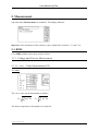
9.4.1. OSC:AMPlitude
This command is required for adjustment or query of the amplitude.
The amplitude determines the value to be multiplied with the value of the waveform memory.
The amplitude value is accepted at the adjusted trigger angle (see 9.4.5).
Execution time: approx. 20ms+1/frequency e.g. 20ms+1/50Hz=40ms
Default value = 0
Group
Oscillator
Syntax
OSC:AMPlitude <INT1>,<FLOAT1><LABEL1>
OSC:AMPlitude <INT1>?
Arguments
<INT1> is the phase number.
Phase: 1 ... 4.
<FLOAT1> is the amplitude value.
Range: +- adjusted range end value (setup:amplifier).
Resolution: range end value/65536, e.g. 270V/65536=0.00412V.
<LABEL1> is the dimension of the amplitude value.
Range: V/A/%.
Return
<FLOAT1>
Examples
osc:amp 1,100%
With this command the amplitude of the first phase is set to 100% of the adjusted amplifier
range.
osc:amp 2,270V
With this command the amplitude of the second phase is adjusted to 270V.
(only at voltage amplifiers)
osc:amp 3,20A
With this command the amplitude of the third phase is adjusted to 20A.
(only at current amplifiers)
osc:amp 1?
Return:
123.4
This query returns an amplitude of 123.4 in the adjusted dimension.
16.07.2013 E_SYC_V6_11.doc
Spitzenberger & Spies GmbH & Co. KG
Page 49
User Manual SyCore
9.4.2. OSC:AMPlitude:ACCept
With this command the acceptance mode for amplitude changes can be switched on/off.
The acceptance mode determines whether an amplitude change is accepted immediately.
Execution time: approx. 20ms
Default= 1 (changes are accepted immediately)
Group
Oscillator
Syntax
OSC:AMPlitude:ACCept <INT1>
OSC:AMPlitude:ACCept?
Arguments
<INT1> is the value for the acceptance mode
1
Acceptance mode on, amplitude changes are accepted immediately.
0
Acceptance mode off, amplitude changes are only accepted when the acceptance
mode is switched on again. Thus it is possible to enable simultaneous changes at
different phases with varying amplitude.
Range:
0-1
Return
<FLOAT1>
Examples
osc:amp:acc 1
With this command the acceptance mode is switched on. Amplitude changes are accepted
immediately.
osc:amp:acc?
Return:
1
The acceptance mode is switched on.
16.07.2013 E_SYC_V6_11.doc
Spitzenberger & Spies GmbH & Co. KG
Page 50
User Manual SyCore
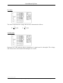
9.4.3. OSC:ANGle
This command is required for the adjustment or query of the phase angle.
The phase angle determines the offset of the waveform memory readout.
The phase angle value is accepted at the adjusted trigger angle. (see 9.1.4).
Execution time: approx. 20ms+1/frequency e.g. 20ms+1/50Hz=40ms
Default value = 0°,120°,240,0°
Group
Oscillator
Syntax
OSC:ANGle <INT1>,<FLOAT1>
OSC:ANGle <INT1>?
Arguments
<INT1> is the phase number.
Range: 1 ... 4.
<FLOAT1> is the phase angle value.
Range: +- 360 in degree.
Resolution: 360/memory depth, e.g. 360/1k=0.35°.
Return
<FLOAT1>
Examples
osc:ang 1,0
With this command the phase angle of the first phase is adjusted to 0°.
osc:ang 2,120
With this command the phase angle of the second phase is adjusted to 120°.
osc:ang 3,240
With this command the phase angle of the third phase is adjusted to 240°.
osc:ang 2?
Return:
120
This query returns a phase angle of 120°.
16.07.2013 E_SYC_V6_11.doc
Spitzenberger & Spies GmbH & Co. KG
Page 51
User Manual SyCore
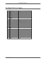
9.4.4. OSC:FREQuency
This command is required for adjustment or query of the frequency.
The frequency determines the clock pulse of the waveform memory.
Execution time: approx. 20ms
Default value = 50 Hz
Group
Oscillator
Syntax
OSC:FREQuency <FLOAT1>
OSC:FREQuency?
Arguments
<FLOAT1> is the frequency value.
Range: fres-fmax (see table below).
Resolution: fres (see table below).
Phase number
Memory depth [B]
1
1
1
1
2
2
2
2
4
4
4
4
1
1
256
1024
4096
16384
256
1024
4096
16384
256
1024
4096
16384
256 (2 Periods)
256 (4 Periods)
Max-Frequency
[Hz]
39062.50
9765.62
2441.40
610.35
19531.25
4882.81
1220.70
305.18
9765.62
2441.40
610.35
152.59
78131.00
156262.00
Frequency resolution
= Min.-Frequency [Hz]
0.298023
0.074506
0.018626
0.004657
0.149012
0.037253
0.009313
0.002328
0.074506
0.018626
0.004657
0.001164
0.596046
1.192092
Return
<FLOAT1>
Examples
osc:freq 50
With this command the frequency is adjusted to 50Hz.
osc:freq?
Return:
50
50Hz are adjusted.
16.07.2013 E_SYC_V6_11.doc
Spitzenberger & Spies GmbH & Co. KG
Page 52
User Manual SyCore
9.4.5. OSC:TRigger
This command is required for adjustment or query of the trigger angle.
The trigger angle determines the moment of acceptance of adjustments like amplitude or
phase angle.
Execution time: approx. 20ms
Default value = 0°
Group
Oscillator
Syntax
OSC:TRigger <FLOAT1>
OSC:TRigger?
Arguments
<FLOAT1> is the phase angle value.
Range: +- 360 in degree.
Resolution: 360/memory depth, e.g. 360/1k=0.35°.
Return
<FLOAT1>
Example
osc:tr 90
With this command the trigger angle is adjusted to 90°.
osc:tr?
Return:
90
This query returns a trigger angle of 90°.
16.07.2013 E_SYC_V6_11.doc
Spitzenberger & Spies GmbH & Co. KG
Page 53
User Manual SyCore
9.4.6. OSC:Sync
This command is required for adjustment and query of the synchronisation between the
oscillator cards.
Execution time: approx. 20ms
Default value = OUT
If there are several oscillator cards in one device, they can be synchronized.
In:
the oscillator is synchronised with the synchronizing pulse of the other internal
oscillator.
Out: the oscillator sets the synchronizing pulse for the other internal oscillator.
Line: the oscillator is synchronised with line signal (only at option “mains synchronous”). If
several oscillators are available all oscillators are set to Line in this operation mode.
Reference: Never set all oscillators to In because this may cause undefined operation modes.
When switching off the operation mode Line, firstly Out has to be set.
Afterwards one of the oscillators can be set to In again.
Group
Oscillator
Syntax
OSC:Sync <STRING1>
OSC:Sync?
Arguments
<STRING1> is the synchron-mode.
Range:
"IN" adjusts to „Synchron in“.
"OUT" adjusts to „Synchron out“.
"LINE" adjusts to „Synchron line“ (optional).
Return
<STRING1>
Example
osc:use 1
osc:sync "OUT"
osc:use 2
osc:sync "IN"
With this command
- the first oscillator card is selected and the synchronisation set to „Out“
- the second oscillator card is selected and the synchronisation set to „In“.
16.07.2013 E_SYC_V6_11.doc
Spitzenberger & Spies GmbH & Co. KG
Page 54
User Manual SyCore
9.4.7. OSC:ADDMult
With this command the adder and multiplier of the oscillator can be adjusted (if multiplier
available).
Execution time: ca. 50ms
Default value = Adder on
Group
Oscillator
Syntax
OSC:ADDMult { 0 | 1}
OSC:ADDMult?
Arguments
0=Adder on
1=Multiplier on
Return
<INT1> (0 or 1)
Examples
osc:addmult 1,0
The adder is switched on in the 1st Phase.
16.07.2013 E_SYC_V6_11.doc
Spitzenberger & Spies GmbH & Co. KG
Page 55
User Manual SyCore
9.4.8. OSC:Use
This command is required for the selection of the active oscillator card.
Execution time: approx. 100ms
Default value = 1
If in one device several oscillator cards are available you can select to which oscillator card
the following adjustments and queries refer.
Group
Oscillator
Syntax
OSC:Use <INT1>
OSC:Use?
Arguments
<INT1> is the number of the oscillator card.
Range: 1 ... 2.
Return
<INT1>
Examples
osc:use 1
osc:amp 4,0%
With this command the first oscillator card is selected and the amplitude of the fourth phase is
adjusted to 0%.
osc:use 2
osc:freq 50
With this command the second oscillator card is selected and the frequency is adjusted to
50Hz.
16.07.2013 E_SYC_V6_11.doc
Spitzenberger & Spies GmbH & Co. KG
Page 56
User Manual SyCore
9.4.9. Conf:Osc:PHases
This command is required for adjustment and query of the number of phases.
The number of phases determines whether the waveform memory is read out for one, two or
four phases.
Execution time: approx. 20ms
Default value = 4 (1 at some special devices)
This command can be used to increase the maximum frequency of four-phase oscillators
when only one phase is required. (See table 9.1.3.)
Syntax
Conf:Osc:PHases <INT1>
Conf:Osc:PHases?
Arguments
<INT1> is the number of phases.
Range: 1, 2, 4.
Return
<INT1 >
Examples
conf:osc:phases 4
With this command the number of phases is adjusted to 4.
conf:osc:phases?
Return:
4
This query returns a phase number of 4.
16.07.2013 E_SYC_V6_11.doc
Spitzenberger & Spies GmbH & Co. KG
Page 57
User Manual SyCore
9.4.10. OSC:APuls:START
This command is required for adjustment and query of the start amplitude of a amplitude
pulse (see 4.4.1).
Execution time: approx. 20ms
Default value = 0
Group
Oscillator
Syntax
OSC:APuls:START <FLOAT1><LABEL1>
OSC:APuls:START?
Arguments
<FLOAT1> is the amplitude value.
Range: +- adjusted range end value (setup:amplifier).
Resolution: range end value/65536, e.g. 270V/65536=0.00412V.
<LABEL1> is the dimension of the amplitude value.
Range: V/A/%.
Return
<FLOAT1>
Examples
osc:apuls:start 230V
With this command the start amplitude is adjusted to 230V.
osc:apuls:start?
Return:
230
This query returns a start amplitude of 230V.
16.07.2013 E_SYC_V6_11.doc
Spitzenberger & Spies GmbH & Co. KG
Page 58
User Manual SyCore
9.4.11. OSC:APuls:PULS
This command is required for adjustment and query of the pulse amplitude of an amplitude
pulse (see 4.4.1).
Execution time: approx. 20ms
Default value = 0
Group
Oscillator
Syntax
OSC:APuls:PULS <FLOAT1><LABEL1>
OSC:APuls:PULS?
Arguments
Amplitude value and dimension (see above).
Return
<FLOAT1>
Examples
osc:apuls:puls 0V
With this command the pulse amplitude is set to 0V.
osc:apuls:puls?
Return:
0
This query returns a pulse amplitude of 0V.
16.07.2013 E_SYC_V6_11.doc
Spitzenberger & Spies GmbH & Co. KG
Page 59
User Manual SyCore
9.4.12. OSC:APuls:END
This command is required for adjustment and query of the end-amplitude of an amplitude
pulse (see 4.4.1).
Execution time: approx. 20ms
Default value = 0
Group
Oscillator
Syntax
OSC:APuls:END <FLOAT1><LABEL1>
OSC:APuls:END?
Arguments
Amplitude value and dimension (see above).
Return
<FLOAT1>
Examples
osc:apuls:end 230V
With this command the end-amplitude is adjusted to 230V.
osc:apuls:end?
Return:
230
This query returns an end-amplitude of 230V.
16.07.2013 E_SYC_V6_11.doc
Spitzenberger & Spies GmbH & Co. KG
Page 60
User Manual SyCore
9.4.13. OSC:APuls:RISET
This command is required for adjustment and query of the rise time of an amplitude pulse (see
4.4.1).
Execution time: approx. 20ms
Default value = 1s
Group
Oscillator
Syntax
OSC:APuls:RISET <FLOAT1>
OSC:APuls:RISET?
Arguments
<FLOAT1> is the time value in seconds
Range: 0 ... 3600.
Return
<FLOAT1>
Examples
osc:apuls:riset 0
With this command the rise time is adjusted to 0s.
osc:apuls:riset?
Return:
0
This query returns a rise time of 0s.
16.07.2013 E_SYC_V6_11.doc
Spitzenberger & Spies GmbH & Co. KG
Page 61
User Manual SyCore
9.4.14. OSC:APuls:DURAT
This command is required for adjustment and query of the pulse duration of an amplitude
pulse (see 4.4.1).
Execution time: approx. 20ms
Default value = 1s
Group
Oscillator
Syntax
OSC:APuls:DURAT <FLOAT1>
OSC:APuls:DURAT?
Arguments
<FLOAT1> is the time value in seconds
Range 0 ... 3600
Return
<FLOAT1>
Examples
osc:apuls:durat 0.02
With this command the pulse time is adjusted to 0.02s.
osc:apuls:durat?
Return:
0.02
This query returns a pulse time of 0.02s.
16.07.2013 E_SYC_V6_11.doc
Spitzenberger & Spies GmbH & Co. KG
Page 62
User Manual SyCore
9.4.15. OSC:APuls:FALLT
This command is required for adjustment and query of the fall time of an amplitude pulse (see
4.4.1).
Execution time: approx. 20ms
Default value = 1s
Group
Oscillator
Syntax
OSC:APuls:FALLT <FLOAT1>
OSC:APuls:FALLT?
Arguments
<FLOAT1> is the time value in seconds
Range 0 ... 3600
Return
<FLOAT1>
Examples
osc:apuls:fallt 0
With this command the fall time is adjusted to 0s.
osc:apuls:fallt?
Return:
0
This query returns a fall time of 0s.
16.07.2013 E_SYC_V6_11.doc
Spitzenberger & Spies GmbH & Co. KG
Page 63
User Manual SyCore
9.4.16. OSC:APuls:REpeats
This command is required for adjustment and query of the number of repeats of an amplitude
pulse (see 4.7.1).
Execution time: approx. 20ms
Default value = 1s
Group
Oscillator
Syntax
OSC:APuls:REpeats <INT1>
OSC:APuls:REpeats?
Arguments
<INT1> is the number of repeats
Range 0 ... 1000 (0 = continuous operation)
Return
<INT1>
Examples
osc:apuls:repeats 2
With this command the number of repeats is adjusted to 2.
osc:apuls:repeats?
Return:
0
This query returns 2 repeats.
16.07.2013 E_SYC_V6_11.doc
Spitzenberger & Spies GmbH & Co. KG
Page 64
User Manual SyCore
9.4.17. OSC:APuls:DElayt
This command is required for adjustment and query of the delay time between the amplitude
pulses (see 4.7.1).
Execution time: approx. 20ms
Default value = 1s
Group
Oscillator
Syntax
OSC:APuls:DElayt <FLOAT1>
OSC:APuls:DElayt?
Arguments
<FLOAT1> is the time value in seconds
Range 0 ... 3600
Return
<FLOAT1>
Examples
osc:apuls:delayt 1
With this command the delay time is adjusted to 1 second.
osc:apuls:delayt?
Return:
1
This query returns a delay time of 1 second.
16.07.2013 E_SYC_V6_11.doc
Spitzenberger & Spies GmbH & Co. KG
Page 65
User Manual SyCore
9.4.18. OSC:APuls:GO
This command is required for the starting of an amplitude pulse (see 4.7.1).
Execution time: ca. 20ms+Risetime+Durationtime+Falltime (see section 9.2)
Default value = none
During the pulse no commands (except BREAK) can be sent (see section 9.5.14).
Group
Oscillator
Syntax
OSC:APuls:GO <INT1>
Arguments
<INT1> is the phase number and/or a combination of the phases
Range: 1 … 4
Return
<INT1>
Example
osc:apuls:go 1234
With this command the amplitude pulse is started on the phases 1, 2, 3 and 4.
osc:apuls:go?
Return:
1234
This query returns the phase numbers 1234; that means the amplitude pulse is executed on
each phase.
16.07.2013 E_SYC_V6_11.doc
Spitzenberger & Spies GmbH & Co. KG
Page 66
User Manual SyCore
9.4.19. OSC:AFPuls:GO
This command is required for the starting of an amplitude and frequency pulse (see 4.7.1).
Execution time: ca. 20ms+Risetime+Durationtime+Falltime (see section 9.2)
Default value = none
During the pulse no commands (except BREAK) can be sent (see section 9.5.14).
Group
Oscillator
Syntax
OSC:AFPuls:GO <INT1>
Arguments
<INT1> is the phase number and/or a combination of the phases
Range: 1 … 4
Return
<INT1>
Example
osc:afpuls:go 1234
With this command the amplitude and frequency pulse is started on the phases 1, 2, 3 and 4.
osc:afpuls:go?
Return:
1234
This query returns the phase numbers 1234; that means the amplitude and frequency pulse is
executed on each phase.
16.07.2013 E_SYC_V6_11.doc
Spitzenberger & Spies GmbH & Co. KG
Page 67
User Manual SyCore
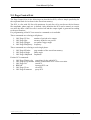
9.4.20. OSC:FPuls:START
This command is required for adjustment and query of the start frequency of a frequency
pulse (see 4.4.2).
Execution time: approx. 20ms
Default value = 50 Hz
Group
Oscillator
Syntax
OSC:FPuls:START <FLOAT1>
OSC:FPuls:START?
Arguments
<FLOAT1> is the frequency value in Hertz.
Range: fres-fmax (see section 9.4.4)
Resolution: fres (see section 9.4.4)
Return
<FLOAT1>
Examples
osc:fpuls:start 50
With this command the start frequency is adjusted to 50Hz.
osc:fpuls:start?
Return:
50
This query returns a start frequency of 50Hz.
16.07.2013 E_SYC_V6_11.doc
Spitzenberger & Spies GmbH & Co. KG
Page 68
User Manual SyCore
9.4.21. OSC:FPuls:PULS
This command is required for adjustment and query of the pulse-frequency of a frequency
pulse (see 4.4.2).
Execution time: approx. 20ms
Default value = 50 Hz
Group
Oscillator
Syntax
OSC:FPuls:PULS <FLOAT1>
OSC:FPuls:PULS?
Arguments
<FLOAT1> is the frequency value in Hertz.
Range: fres-fmax (see section 9.4.4)
Resolution: fres (see section 9.4.4)
Return
<FLOAT1>
Examples
osc:fpuls:puls 150
With this command the pulse-frequency is adjusted to 150Hz.
osc:fpuls:puls?
Return:
150
This query returns a pulse frequency of 150Hz.
16.07.2013 E_SYC_V6_11.doc
Spitzenberger & Spies GmbH & Co. KG
Page 69
User Manual SyCore
9.4.22. OSC:FPuls:END
This value is required for adjustment and query of the end-frequency of a frequency pulse
(see 4.4.2).
Execution time: ca. 20ms
Default value = 50 Hz
Group
Oscillator
Syntax
OSC:FPuls:END <FLOAT1>
OSC:FPuls:END?
Arguments
<FLOAT1> is the frequency value in Hertz.
Range: fres-fmax (see section 9.4.4)
Resolution: fres (see section 9.4.4)
Return
<FLOAT1>
Examples
osc:fpuls:end 50
With this command the end-frequency is adjusted to 50Hz.
osc:fpuls:end?
Return:
50
This query returns an end-frequency of 50Hz.
16.07.2013 E_SYC_V6_11.doc
Spitzenberger & Spies GmbH & Co. KG
Page 70
User Manual SyCore
9.4.23. OSC:FPuls:RISET
This command is required for adjustment and query of the rise time of a frequency pulse (see
4.4.2).
Execution time: approx. 20ms
Default value = 1s
Group
Oscillator
Syntax
OSC:FPuls:RISET <FLOAT1>
OSC:FPuls:RISET?
Arguments
<FLOAT1> is the time value in seconds
Range: 0 ... 3600.
Return
<FLOAT1>
Examples
osc:fpuls:riset 0
With this command the rise time is adjusted to 0s.
osc:fpuls:riset?
Return:
0
This query returns a rise time of 0s.
16.07.2013 E_SYC_V6_11.doc
Spitzenberger & Spies GmbH & Co. KG
Page 71
User Manual SyCore
9.4.24. OSC:FPuls:DURAT
This command is required for adjustment and query of the duration of a frequency pulse (see
4.4.2).
Execution time: approx. 20ms
Default value = 1s
Group
Oscillator
Syntax
OSC:FPuls:DURAT <FLOAT1>
OSC:FPuls:DURAT?
Arguments
<FLOAT1> is the time value in seconds
Range: 0 ... 3600.
Return
<FLOAT1>
Examples
osc:fpuls:durat 0.02
With this command the duration is adjusted to 0.02s.
osc:fpuls:durat?
Return:
0.02
This query returns a duration of 0.02.
16.07.2013 E_SYC_V6_11.doc
Spitzenberger & Spies GmbH & Co. KG
Page 72
User Manual SyCore
9.4.25. OSC:FPuls:FALLT
This command is required for adjustment and query of the fall time of a frequency pulse (see
section 4.7.2).
Execution time: ca. 20ms
Default value = 1s
Group
Oscillator
Syntax
OSC:FPuls:FALLT <FLOAT1>
OSC:FPuls:FALLT?
Arguments
<FLOAT1> is the time value in seconds
Range: 0 ... 3600.
Return
<FLOAT1>
Examples
osc:fpuls:fallt 0
With this command the fall time is adjusted to 0s.
osc:fpuls:fallt?
Return:
0
This query returns a fall time of 0s.
16.07.2013 E_SYC_V6_11.doc
Spitzenberger & Spies GmbH & Co. KG
Page 73
User Manual SyCore
9.4.26. OSC:FPuls:REpeats
This command is required for adjustment and query of the number of repeats of a frequency
pulse (see 4.7.2).
Execution time: approx. 20ms
Default value = 1s
Group
Oscillator
Syntax
OSC:FPuls:REpeats <INT1>
OSC:FPuls:REpeats?
Arguments
<INT1> is the number of repeats
Range 0 ... 1000 (0 = continuous mode)
Return
<INT1>
Examples
osc:fpuls:repeats 2
With this command the number of repeats is adjusted to 2.
osc:fpuls:repeats?
Return:
0
This query returns 2 repeats.
16.07.2013 E_SYC_V6_11.doc
Spitzenberger & Spies GmbH & Co. KG
Page 74
User Manual SyCore
9.4.27. OSC:FPuls:DElayt
This command is required for adjustment and query of the delay time between the frequency
pulses (see 4.7.2).
Execution time: approx. 20ms
Default value = 1s
Group
Oscillator
Syntax
OSC:FPuls:DElayt <FLOAT1>
OSC:FPuls:DElayt?
Arguments
<FLOAT1> is the time value in seconds
Range 0 ... 3600
Return
<FLOAT1>
Examples
osc:fpuls:delayt 1
With this command the delay time is adjusted to 1 second.
osc:fpuls:delayt?
Return:
1
This query returns a delay time of 1 second.
16.07.2013 E_SYC_V6_11.doc
Spitzenberger & Spies GmbH & Co. KG
Page 75
User Manual SyCore
9.4.28. OSC:FPuls:GO
This command is required for the starting of a frequency pulse (see section 4.7.2).
Execution time: approx. 20ms+Risetime+Durationtime+Falltime (see section 9.2)
Default value = none
During the pulse no commands (except BREAK) can be sent (see section 9.5.14).
Group
Oszillator
Syntax
OSC:FPuls:GO
Arguments
Return
Example
osc:fpuls:go
With this command the frequency pulse is started.
16.07.2013 E_SYC_V6_11.doc
Spitzenberger & Spies GmbH & Co. KG
Page 76
User Manual SyCore
9.5. Page Control List
The Page Control List (in the following text described as PCL) offers a simple possibility for
the sequential link of waveform in the waveform memory.
The PCL is a list with 256 list cells maximum. In each list cell a waveform with its features
like amplitude, phase angle etc. is defined. After definition the PCL can be started, as a result,
one after the other of the list cells is worked off and the output signal is generated according
to the specifications.
For programming of the PCL an extensive command set is available.
These commands are referring to all phases:
1.
2.
3.
4.
OSC:Page:CYcles
number of periods to be output
OSC:Page:SIze
memory depth for one period
OSC:Page:TRigger
acceptance trigger angle
OSC:Page:FRequency frequency
These commands are referring to each single phase:
1. OSC:Page:NUmber
2. OSC:Page:ANngle
3. OSC:Page:AMplitude
page number of the waveform memory
phase angle
amplitude
Further PCL commands:
1.
2.
3.
4.
5.
6.
OSC:Page:TOtalcycles
OSC:Page:STop-number
OSC:Page:GO
BREAK
OSC:Page:CLear
OSC:Page:PArameter
repetitions for the whole PCL
defines continuation of PCL after execution
start PCL
interrupt PCL run
clear PCL
query PCL
16.07.2013 E_SYC_V6_11.doc
Spitzenberger & Spies GmbH & Co. KG
Page 77
User Manual SyCore
Schematic memory division of the PCL in relation with the waveform memory:
NOTICE: Once activated, an adjustment keeps its validity until it is overwritten in a later list
cell.
Example: If in list cell 1 a frequency of 50Hz is defined, this frequency remains valid for all
following list cells until a new frequency is defined in a later list cell.
This is also valid at PCL start: The settings made by using normal commands (or manual
settings) like osc:amplitude or osc:frequency remain valid until they are overwritten by the
PCL.
For the programming of the PCL the following scheme should be used:
1. Clear PCL (command: OSC:Page:Clear)
2. Program the PCL with the requested function.
3. Deposit the requested waveform in the waveform memory
4. Start PCL (OSC:Page:GO)
16.07.2013 E_SYC_V6_11.doc
Spitzenberger & Spies GmbH & Co. KG
Page 78
User Manual SyCore
9.5.1. OSC:Page:CYcles
This command defines how often the contents of a waveform memory (page) are output.
Syntax
OSC:Page:CYcles <INT1>,<INT2>
Arguments
<INT1>
List cell number
Valid range: 1 ... 256
<INT2>
Number of repeats (periods)
Valid range: 1 ... 32767
(the valid range of some older devices is 1 ... 1000)
Default value after „osc:page:clear“: 0
0 means no execution of the current list cell
Examples
osc:page:cycles 2,5
With this command a repeat value of 5 is stored in the list cell 2.
After starting the PCL and reaching the list cell 2 the current waveform memory is output five
times.
16.07.2013 E_SYC_V6_11.doc
Spitzenberger & Spies GmbH & Co. KG
Page 79
User Manual SyCore
9.5.2. OSC:Page:SIze
With this command the memory depth (pagesize) for a waveform output is defined.
Syntax
OSC:Page:Size <INT1>,{ 0 | 1 | 4 | 16 | 64 | 256 | 1024 }
Arguments
<INT1>
List cell number
Valid range: 1-256
{ 0 | 1 | ... }
Memory depth for a waveform
Valid arguments:
0
= 0.25Kbyte / 256 points
1
= 1Kbyte / 1024 points
4
= 4Kbyte / 4096 points
16 = 16Kbyte / 16384 points
64 = 64Kbyte / 65536 points
256 = 256Kbyte / 264144 points
1024 = 1024Kbyte / 1048576 points
(only at 64kB or 1MB Oscillator)
(only at 64kB or 1MB Oscillator)
(only at 64kB or 1MB Oscillator)
(only at 1MB Oscillator)
(only at 1MB Oscillator)
The whole waveform memory has a size of 1K (1024), 64K (65536) or 1M (1048576) points
(dependent on its configuration)
The maximum number of waveform memories (pages) is calculated from the size of the
whole waveform memory and the adjusted memory depth.
e.g. 1M (1048576)/1K (1024)=1K (1024) pages.
Examples
osc:page:size
1,1
With this command a waveform memory depth of 1024 points is adjusted for the list cell 1.
16.07.2013 E_SYC_V6_11.doc
Spitzenberger & Spies GmbH & Co. KG
Page 80
User Manual SyCore
9.5.3. OSC:Page:TRigger
This command defines the trigger angle for the acceptance of the next list cell values.
Syntax
OSC:Page:TRigger <INT1>,<FLOAT1>
Arguments
<INT1>
List cell number
Valid range: 1 ... 256
<FLOAT1>
Trigger angle value for the acceptance of the next list cell values.
Valid range: 0 ... 360° (floating-point number)
The possible angle resolution depends on the waveform memory depth. By means of the
following formula the angle resolution can be calculated:
Smallest possible resolution = 360 / waveform memory depth.
e.g. 360°/1024 = 0.351°
Example
osc:page:trigger 1,90
With this command a trigger angle of 90° is stored in the list cell 1.
9.5.4. OSC:Page:FRequency
With this command the frequency for a waveform output can be programmed.
Note: The frequency adjustment is valid for all phases of the current oscillator card.
Syntax
OSC:Page:FRequency <INT1>,<FLOAT1>
Arguments
<INT1>
List cell number
Valid range: 1 ... 256
<FLOAT1>
Defines the frequency
The minimum frequency, the maximum frequency and the frequency resolution depend on
several factors, e.g. the waveform memory depth or the number of phases. See also section
„memory depth“ for further details.
Examples
osc:page:frequency 1,50
With this command a frequency of 50Hz is stored in the list cell 1.
16.07.2013 E_SYC_V6_11.doc
Spitzenberger & Spies GmbH & Co. KG
Page 81
User Manual SyCore
9.5.5. OSC:Page:NUmber
This command assigns a waveform memory page to the requested phase in a list cell.
Note: The same waveform memory (page) can be assigned to several list cells.
Syntax
OSC:Page:NUmber <INT1>,<INT2>,<INT3>
Arguments
<INT1>
List cell number
Valid range: 1 ... 256
<INT2>
Phase number
Valid range: 1 ... 4
<INT3>
Page number: 1 ... XXX
The maximum page number depends on several factors.
(see: OSC:Page:SIze)
Example:
osc:page:number 1,1,1
osc:page:number 1,2,1
osc:page:number 1,3,1
osc:page:angle 1,1,0
osc:page:angle 1,2,120
osc:page:angle 1,3,240
The same waveform memory is assigned to the three phases of list cell 1. The different phase
angles result in a three-phase system.
16.07.2013 E_SYC_V6_11.doc
Spitzenberger & Spies GmbH & Co. KG
Page 82
User Manual SyCore
9.5.6. OSC:Page:ANgle
This value indicates the phase angle of the waveform memory (page) is output.
Syntax
OSC:Page:ANgle <INT1>,<INT2>,<FLOAT1>
Arguments
<INT1>
List cell number
Valid range: 1 ... 256
<INT2>
Phase number
Valid range: 1 ... 4
<FLOAT1>
Start angle the output of the waveform memory is started with. Corresponds
to a phase shift against pseudo-phase 0.
Valid range: 0 ... 360° (floating-point number)
The maximally possible angle resolution depends on the waveform memory depth. With the
following formula the angle resolution can be calculated:
Smallest possible resolution = 360 / waveform memory depth.
e.g. 360/1024 = 0.351 degree.
Examples:
osc:page:angle 1,1,90
With this command a phase angle of 90° is stored in the list cell 1.
16.07.2013 E_SYC_V6_11.doc
Spitzenberger & Spies GmbH & Co. KG
Page 83
User Manual SyCore
9.5.7. OSC:Page:AMplitude
This command defines the amplitude for a waveform output.
Syntax
OSC:Page:AMplitude <INT1>,<INT2>,<FLOAT1>
Arguments
<INT1>
List cell number
Valid range: 1 ... 256
<INT2>
Phase number
Valid range: 1 ... 4
<FLOAT1>
Proportional amplitude value with which the content of the waveform
memory is output.
Valid range: 0 ... 100 (floating-point number)
A proportional amplitude value of 100 corresponds to the current amplifier range end value.
Proportional amplitude = amplitude / range end value * 100
For adjusting an output voltage of 230V AC at a 270V AC-standard amplifier a amplitude
value of 81.18% has to be programmed.
Examples
osc:page:amplitude 1,3,50
With this command an amplitude of 50% for phase 3 is stored in list cell 1.
16.07.2013 E_SYC_V6_11.doc
Spitzenberger & Spies GmbH & Co. KG
Page 84
User Manual SyCore
9.5.8. OSC:Page:PULS
With this command the pulse operation can be enabled (see section 9.5.1) within the
PageControlList (if available).
Before using the pulse operation a 30ms pre-lead time is required during PCL-cycle (for
shifting-up of the power supply by hardware).
This command shall also be sent in a preceding page.
Execution time: ca.30ms
Default:
0
Syntax
OSC:PAGE:PULSE <INT1>,<INT2>
Argumente
<INT1>
List cell number
Valid range: 1 … 256
<INT2>
Switch pulse operation
Valid range: 0 = OFF , 1 = positive, 2 = negative
Examples
osc:page:pulse 3,1
Switches the positive pulse operation in the 3rd page. After 30ms it can be used.
osc:page:pulse 6,0
Switches off the pulse operation in the 6th page.
16.07.2013 E_SYC_V6_11.doc
Spitzenberger & Spies GmbH & Co. KG
Page 85
User Manual SyCore
9.5.9. OSC:Page:FUnction
This command is required for generation and query of a waveform.
Execution time: approx. 0.25s per 1k depth
Default value = SINE
Note: amplitude 1 ... 4 is adjusted to 0.
Syntax
OSC:Page:FUnction <INT1>,<STRING1>
OSC:Page:FUnction?
Arguments
<INT1> is the phase number.
<STRING1> is the type of function.
Possible values:
"SINE" generates a sine waveform.
"PULS" generates a pulse waveform.
"TRIA" generates a triangle waveform.
"RAMP" generates a ramp waveform (saw-tooth).
"RECT" generates a rectangle waveform.
"DC" generates a DC waveform.
Return
<STRING1>
Examples
osc:page:function 1,"SINE"
With this command a sine-waveform is generated.
osc:page:function 1?
Return:
"SINE"
This query returns a sine-waveform.
16.07.2013 E_SYC_V6_11.doc
Spitzenberger & Spies GmbH & Co. KG
Page 86
User Manual SyCore
9.5.10. OSC:Page:TOtalcycles
This value indicates how often the output of the whole PCL is repeated.
Syntax
OSC:Page:TOtalcycles <INT1>
Arguments
<INT1>
Number of repetitions
Valid range: 1 ... 1000
Default value after „osc:page:clear“: 0
Examples:
osc:page:totalcycles 2
With this command the value 2 is stored.
The complete PCL is running twice.
9.5.11. OSC:Page:STopnumber
This value indicates which list cell is running after a „BREAK“-command before PCL is
stopped. 0 means output of the current list cell at the moment of the BREAK command.
Syntax
OSC:Page:Stop-number <INT1>
Arguments
<INT1>
List cell number
Valid range: 0 ... 256
Above all, this command is useful for the program development e.g. for defined interrupting
of many repetitions (cycles).
Examples
osc:page:stop-number 10
With this command list cell 10 is defined as stop list cell.
9.5.12. OSC:Page:GO
With this command the PCL run is started (see section 9.2).
Syntax
OSC:Page:GO
Arguments
None
NOTICE: During the PCL run no commands should be sent to the SyCore.
Exception: „BREAK“
Examples
osc:page:go
Start of PCL
16.07.2013 E_SYC_V6_11.doc
Spitzenberger & Spies GmbH & Co. KG
Page 87
User Manual SyCore
9.5.13. OSC:Page:GOBY trigger (optional)
With this command the PCL is armed for the start with an external trigger. (only when
trigger card is installed). Now the run can be started by a start-trigger (please see section
10.6).
Syntax
OSC:Page:GOBYtrigger
Arguments
None
Reference: During the run of the PLC no commands can be sent to the SyCore (except
„BREAK“ and „OSC:Page:STopnumber“).
Examples
osc:page:gobytrigger
The PCL is armed for the start by trigger.
9.5.14. BREAK
With this command a running PCL run can be interrupted.
Syntax
BREAK
Arguments
None
At „BREAK“ the run of the current list cell is interrupted. If stop-number=0 is programmed
an immediate interrupt happens. Otherwise the list cell defined by stop-number runs and the
PCL is finished.
Examples
BREAK
With this command the running PCL is interrupted.
9.5.15. OSC:Page:CLear
This command is meant for clearing the complete PCL.
Syntax
OSC:Page:CLear
Arguments
None
Examples
osc:page:clear
With this command all adjustments in the list are cleared.
9.5.16. OSC:Page:PArameter
With this command the content of a list cell can be read out.
16.07.2013 E_SYC_V6_11.doc
Spitzenberger & Spies GmbH & Co. KG
Page 88
User Manual SyCore
Syntax
OSC:Page:PArameter <INT1>?
Arguments
<INT1>
List cell number
Valid range: 1 ... 256
Return
<String>
Format:
TO=[TotalCycles],ST=[Stop],CY=[Cycles],
SI=[Size],TR=[Trigger],FR=[Frequency],
NU=[1][Number P1],[2][Number P2],[3][Number P3],[4][Number P4],
AN=[1][Angle P1],[2][Angle P2],[3][Angle P3],[4][Angle P4],
AM=[1][Amplitude P1],[2][Amplitude P2],[3][Amplitude P3],[4][Amplitude P4]
Examples
osc:page:parameter 1?
Return:
TO=1,ST=0,CY=1,
SI=1,TR=90,FR=50,
NU=[1]1,[2]1,[3]1,[4]1,
AN=[1]0,[2]120,[3]240,[4]0,
NU=[1]230,[2]230,[3]230,[4]1
9.5.17. OSC:Page:PEriods
With this command the frequency can be multiplied with the factor x in order to increase the
maximum frequency range.
Syntax
OSC:Page:PEriods <INT1>
Arguments
<INT1>
Multiplication factor x
valied factors: 1, 2, 4, 8
Example
osc:page:periods 4
The maximum frequency is increased by the factor 4.
Current maximum frequency range: 2441Hz
Increased maximum frequency range: 9764Hz
16.07.2013 E_SYC_V6_11.doc
Spitzenberger & Spies GmbH & Co. KG
Page 89
User Manual SyCore
9.5.18. OSC:Page:MEMory
This command is required for adjustment and query of the memory depth.
The memory depth determines the size of the waveform memory to be read out.
Execution time: approx. 20ms
Default value = 1k points
After the adjustment the waveform has to be re-generated.
Note: amplitude 1 ... 4 is adjusted to 0.
Group
Oszillator
Syntax
OSC:Page:MEMory <INT1>
OSC:Page:MEMory?
Arguments
<INT1> is the memory depth.
Possible values:
0 = 256 points .
1 = 1024 points .
4 = 4096 points
(only at 64kB or 1MB Oscillator)
16 = 16384 points
(only at 64kB or 1MB Oscillator)
64 = 65536 points
(only at 64kB or 1MB Oscillator)
256 = 264144 points
(only at 1MB Oscillator)
1024 = 1048576 points
(only at 1MB Oscillator)
Return
<INT1>
Examples
osc:page:mem 1
With this command a memory depth of 1 (1024 points) is adjusted.
osc:page:mem?
Return:
1
This query returns a memory depth of 1 (1024 points).
16.07.2013 E_SYC_V6_11.doc
Spitzenberger & Spies GmbH & Co. KG
Page 90
User Manual SyCore
9.5.19. Examples
Example 1:
Generate a 10% amplitude magnification for one period (20ms).
Proceeding 1
A page with a stored sine is required. When using a standard oscillator the page 1 is already
initialised with sine (50Hz) after switching on. This is the standard page for the output of the
waveform (see section 4.2). The first PCL list cell is used for the rise, the second one for the
remaining state.
Example with SPS-Scriptmanager:
send 6,10,"osc:amplitude 1,85%"
send 6,10,"osc:page:clear"
send 6,10,"osc:page:cycles 1,1"
send 6,10,"osc:page:amplitude 1,1,93.7"
send 6,10,"osc:page:cycles 2,1"
send 6,10,"osc:page:amplitude 2,1,85"
send 6,10,"osc:page:totalcycles 1"
send 6,10,"osc:page:go"
//Amplitude of phase 1 at 85%
//in 270V range=230V
//PCL clear
//List cell 1: output 1x page
//List cell 1: amplitude of Phase 1 at 93.7%
//in 270V range=253V
//List cell 2: output 1x page *
//List cell 2: amplitude of phase 1 again
//at 85% in 270V range=230V
//output 1x PCL
//start PCL
* After this cycle the output remains on this page. However, the smallest possible value ( 1 )
should be adjusted to make the fixed run of the PCL as short as possible.
Measured signal at oscillator output:
16.07.2013 E_SYC_V6_11.doc
Spitzenberger & Spies GmbH & Co. KG
Page 91
User Manual SyCore
Proceeding 2
For a better illustration of the functionality the same rise is generated in another way.
A page with a stored sine is required as well. Page 1 is used for standard page for the output
of the waveform (see section 4.2) as well. The first PCL list cell is used for the adjustment of
the operation voltage, the second for the rise.
Example with SPS-Scriptmanager:
send 6,10,"osc:page:clear"
//PCL clear
send 6,10,"osc:page:cycles 1,1"
//List cell 1: output page 1x
send 6,10,"osc:page:amplitude 1,1,85"
//List cell 1: amplitude of phase 1 at 85%
//in 270V range=230V
send 6,10,"osc:page:cycles 2,1"
//List cell 2: output page 1x
send 6,10,"osc:page:amplitude 2,1,93.7"
//List cell 2: amplitude of phase 1 at 93.7%
//in 270V range=253V
send 6,10,"osc:page:stopnumber 1"
//after run of the PCL List cell 1
//is output
send 6,10,"osc:page:totalcycles 1"
//output 1x PCL
send 6,10,"osc:page:go"
//start PCL
Because 230V should be output again after the cycle a stop number is defined here.
16.07.2013 E_SYC_V6_11.doc
Spitzenberger & Spies GmbH & Co. KG
Page 92
User Manual SyCore
Example 2:
Generation of a ring-waveform (for 64k oscillator).
Duration: one period (20ms) .
First of all the following waveform has to be transferred into phase 2 (page 17).
Example in C:
Ieee.SendString(6, "DATA:POINTER 1,32768");
Wait(10);
Ieee.SendString(6, DATA:SIZE 2048");
Wait(10);
Ieee.SendString(6,"DATA:SET");
Wait(10);
Ieee.Transmit("UNL UNT MTA LISTEN6");
Wait(10);
Ieee.TransmitArray(Value,(uint)ActTransferPoints*2);
Wait(10);
Ieee.SendString(6,"DATA:WRITE");
Wait(1000);
//Set data destination at phase 2
//Set data size for 1K curve
//Set transfer mode
//Address SyCore as Listener
//Transfer data into IEEE-Buffer
//Copy data from IEEE-Buffer
//to oscillator-waveform memory
16.07.2013 E_SYC_V6_11.doc
Spitzenberger & Spies GmbH & Co. KG
Page 93
User Manual SyCore
Proceeding
A page with a stored sine is required. When using a standard oscillator the page 1 is already
initialised with sine (50Hz) after switching on. This is the standard page for the output of the
waveform (see section 4.2). The transferred ring-waveform is now in page 17. The first PCL
list cell is used for the ring-waveform, the second one for the remaining state.
Example with SPS-ScriptManager:
send 6,10,"osc:amplitude 1,50%"
send 6,10,"osc:page:clear"
send 6,10,"osc:page:cycles 1,1"
send 6,10,"osc:page:number 1,1,17"
send 6,10,"osc:page:amplitude 1,1,100"
send 6,10,"osc:page:cycles 2,1"
send 6,10,"osc:page:number 2,1,1"
send 6,10,"osc:page:amplitude 2,1,50"
send 6,10,"osc:page:totalcycles 1"
send 6,10,"osc:page:go"
//Amplitude of Phase 1 at 50%
//in 270V range=135V
//PCL clear
//List cell 1: output page 1x
//List cell 1: waveform memory of phase 1
//(Page 1) set to waveform memory of phase 2
//(Page 17) , (at 64kByte oscillators)
//List cell 1: amplitude of phase 1 at 100%
//List cell 2: output page 1x *
//List cell 1: waveform memory of Phase 1
//(Page 17) re-set waveform memory to phase 1
//(Page 1)
//List cell 2: amplitude of phase 1 at 50%
//in 270V range=135V
//output a PCL
//start PCL
* After this cycle the output remains on this page. However, the smallest possible value ( 1 )
should be adjusted to make the fixed run of the PCL as short as possible.
16.07.2013 E_SYC_V6_11.doc
Spitzenberger & Spies GmbH & Co. KG
Page 94
User Manual SyCore
Example in C:
Ieee.SendString(6,"osc:amplitude 1,50%");
Wait(10);
Ieee.SendString(6,"osc:page:clear");
Wait(10);
Ieee.SendString(6,"osc:page:cycles 1,1");
Wait(10);
Ieee.SendString(6,"osc:page:number 1,1,17");
Wait(10);
//amplitude of phase 1 at 50%
//in 270V range=135V
//clear PCL
//List cell 1: output page 1x
//List cell 1: set waveform memory of
//phase 1 (page 1) to waveform memory
//of phase 2 (page 17)
Ieee.SendString(6,"osc:page:amplitude 1,1,100"); //List cell 1: amplitude of phase 1
Wait(10);
//at 100% in 270V range=270V
Ieee.SendString(6,"osc:page:cycles 2,1");
//List cell 2: output page 1x *
Wait(10);
Ieee.SendString(6,"osc:page:number 2,1,1");
//List cell 1: re-set waveform memory of
Wait(10);
//phase 1 (Page 17) to waveform memory
//of phase 1 (Page 1)
Ieee.SendString(6,"osc:page:amplitude 2,1,50"); //List cell 2: amplitude of phase 1
Wait(10);
//at 50% in 270V range=135V
Ieee.SendString(6,"osc:page:totalcycles 1");
//output a PCL
Wait(10);
Ieee.SendString(6,"osc:page:go");
//start PCL
Wait(10);
* After this cycle the output remains on this page. However, the smallest possible value ( 1 )
should be adjusted to make the fixed run of the PCL as short as possible.
Measured signal at oscillator output:
16.07.2013 E_SYC_V6_11.doc
Spitzenberger & Spies GmbH & Co. KG
Page 95
User Manual SyCore
9.6. Measurement
The measurement sub-system is structured as follows:
MEAS
:VOLTage?
:CURRent?
:POWer?
:S?
:Q?
:PF?
:UP?
:IP?
:CFU?
:CFI?
:FREQuency?
Conf
:Meas
:Mode
:ac
:dc
:acdc
:PH
:Use
16.07.2013 E_SYC_V6_11.doc
Spitzenberger & Spies GmbH & Co. KG
Page 96
User Manual SyCore
9.6.1. MEAS:VOLTage
With this command the voltage value can be queried.
Execution time: approx. 200ms for the first query; 20 ms for the following queries
Default value = None
Group
Measurement
Syntax
MEAS:VOLTage?
Arguments
Query only
Return
<FLOAT1>
Example
meas:voltage?
Return:
230.000
This query returns a voltage value of 230V.
9.6.2. MEAS:CURRent
With this command the current value can be queried.
Execution time: approx. 200ms for the first query; 20 ms for the following queries
Default value = None
Group
Measurement
Syntax
MEAS:CURRent?
Arguments
Query only
Return
<FLOAT1>
Example
meas:current?
Return:
50.000
This query returns a current value of 50A.
16.07.2013 E_SYC_V6_11.doc
Spitzenberger & Spies GmbH & Co. KG
Page 97
User Manual SyCore
9.6.3. MEAS:POWer
With this command the power value can be queried.
Execution time: approx. 200ms for the first query; 20 ms for the following queries
Default value = None
Group
Measurement
Syntax
MEAS:POWer?
Arguments
Query only
Return
<FLOAT1>
Example
meas:power?
Return:
500.000
This query returns an active power value of 500W.
9.6.4. MEAS:S
With this command the apparent power value can be queried.
Execution time: approx. 200ms for the first query; 20 ms for the following queries
Default value = None
Group
Measurement
Syntax
MEAS:S?
Arguments
Query only
Return
<FLOAT1>
Example
meas:s?
Return:
500.000
This query returns an apparent power value of 500VA.
16.07.2013 E_SYC_V6_11.doc
Spitzenberger & Spies GmbH & Co. KG
Page 98
User Manual SyCore
9.6.5. MEAS:Q
With this command the reactive power value can be queried.
Execution time: approx. 200ms for the first query; 20 ms for the following queries
Default value = None
Group
Measurement
Syntax
MEAS:Q?
Arguments
Query only
Return
<FLOAT1>
Example
meas:q?
Return:
50.000
This query returns a reactive power value of 50VAr.
9.6.6. MEAS:PF
With this command the power factor value can be queried.
Execution time: approx. 200ms for the first query; 20 ms for the following queries
Default value = None
Group
Measurement
Syntax
MEAS:PF?
Arguments
Query only
Return
<FLOAT1>
Example
meas:pf?
Return:
0.75
This query returns power factor 0.75.
16.07.2013 E_SYC_V6_11.doc
Spitzenberger & Spies GmbH & Co. KG
Page 99
User Manual SyCore
9.6.7. MEAS:UP
With this command the voltage peak value can be queried.
Execution time: approx. 200ms for the first query; 20 ms for the following queries
Default value = None
Group
Measurement
Syntax
MEAS:UP?
Arguments
Query only
Return
<FLOAT1>
Example
meas:up?
Return:
325.000
This query returns a voltage value of 325p.
9.6.8. MEAS:IP
With this command the current peak value can be queried.
Execution time: approx. 200ms for the first query; 20 ms for the following queries
Default value = None
Group
Measurement
Syntax
MEAS:IP?
Arguments
Query only
Return
<FLOAT1>
Example
meas:ip?
Return:
70.000
This query returns a current value of 70Ap.
16.07.2013 E_SYC_V6_11.doc
Spitzenberger & Spies GmbH & Co. KG
Page 100
User Manual SyCore
9.6.9. MEAS:CFU
With this command the voltage crest-factor value can be queried.
Execution time: approx. 200ms for the first query; 20 ms for the following queries
Default value = None
Group
Measurement
Syntax
MEAS:CFU?
Arguments
Query only
Return
<FLOAT1>
Example
meas:cfu?
Return:
1.41
This query returns a crest factor of 1.41.
9.6.10. MEAS:CFI
With this command the current crest-factor value can be queried.
Execution time: approx. 200ms for the first query; 20 ms for the following queries
Default value = None
Group
Measurement
Syntax
MEAS:CFI?
Arguments
Query only
Return
<FLOAT1>
Example
meas:cfi?
Return:
1.75
This query returns a crest factor of 1.75.
16.07.2013 E_SYC_V6_11.doc
Spitzenberger & Spies GmbH & Co. KG
Page 101
User Manual SyCore
9.6.11. MEAS:FREQuency
With this command the frequency value of the voltage can be queried.
Execution time: approx. 200ms for the first query; 20 ms for the following queries
Default value = None
Group
Measurement
Syntax
MEAS:FREQuency?
Arguments
Query only
Return
<FLOAT1>
Example
meas:frequency?
Return:
50.000
This query returns a frequency value of 50Hz.
9.6.12. Conf:Meas:Mode
This command selects the current measurement mode (coupling).
Execution time: approx. 200ms
Default value = AC
The input of the measurement card is equipped with a coupling capacitor which is bridged in
ACDC and DC mode but not in AC mode.
Group
Measurement
Syntax
Conf:Meas:Mode:{ AC | DC | ACDC }
Arguments
AC switches to AC measurement mode for voltage and current
DC switches to DC measurement mode for voltage and current
ACDC switches to ACDC measurement mode for voltage and current
Return
-Example
conf:meas:mode:acdc
This command switches to mixed signal measurement (AC and DC) for voltage and current.
16.07.2013 E_SYC_V6_11.doc
Spitzenberger & Spies GmbH & Co. KG
Page 102
User Manual SyCore
9.6.13. Conf:Meas:PH
This command selects the current measurement phase.
Execution time: approx. 200ms
Default value = 1
If you have got several measurement inputs you can route the input pair (U/I) to the input pair
of the measurement card.
Group
Measurement
Syntax
Conf:Meas:PH <INT1>
Conf:Meas:PH?
Arguments
<INT1> no. of measurement phase.
Range: 1 ... 3
Return
<INT1>
Example
conf:meas:ph 1
This example switches the current measurement phase to phase 1.
16.07.2013 E_SYC_V6_11.doc
Spitzenberger & Spies GmbH & Co. KG
Page 103
User Manual SyCore
9.6.14. Meas:Use
This command selects the currently active measurement card
Execution time : approx. 200ms
Default value = 1
If you have got several measurement cards installed in your system you can select the
currently active card with this command. All the following settings and queries are related to
this card until you select a different one.
Group
Measurement
Syntax
Meas:Use <INT1>
Meas:Use?
Arguments
<INT1> no. of the measurement card
Range: 1 ... 2
Return
<INT1>
Examples
meas:use 1
meas:voltage?
This command selects measurement card 1 and queries the currently measured voltage.
meas:use 2
meas:voltage?
This command selects measurement card 2 and queries the currently measured voltage.
16.07.2013 E_SYC_V6_11.doc
Spitzenberger & Spies GmbH & Co. KG
Page 104
User Manual SyCore
9.7. Control
The control subsystem is structured as follows:
Conf
:Amp
:Range
Status
:Amp
AMP
:Output
:Range
:Mode
:ON
:Power
:Pulse
:Par
:Q
IMP
:Phase
:Range
:Mode
:Harm
:Range
INRush
:Current
:Source
Status
:Curr
CURR
:Limitation
:Control
:Mode
:Level
16.07.2013 E_SYC_V6_11.doc
Spitzenberger & Spies GmbH & Co. KG
Page 105
User Manual SyCore
9.7.1. AMP:Output
This command switches the amplifier output.
Execution time: max. 2s
Default value=0
Group
Amplifier
Syntax
AMP:Output { 0 | 1 }
AMP:Output?
Arguments
0 switches the output off
1 switches the output on
Return
0 or 1
Example
amp:output 1
This example switches the output on.
9.7.2. AMP:Range
This command selects the amplifier range. When the amplifier range is changed the output
and the control are reset.
Execution time: min. 2s (depends on type of amplifier)
Default value = lowest range which is higher than 230V
Group
Amplifier
Syntax
AMP:Range <INT1>
AMP:Range?
Arguments
<INT1> range number
Return
<INT1>
Example
amp:range 1
This command switches the amplifier range to range 1.
16.07.2013 E_SYC_V6_11.doc
Spitzenberger & Spies GmbH & Co. KG
Page 106
User Manual SyCore
9.7.3. AMP:Mode
This command switches the amplifiers input mode.
Execution time: approx. 50ms
Default value = AC
Group
Amplifier
Syntax
AMP:Mode:{ AC | DC }
Arguments
AC switches to AC mode
DC switches to DC mode
Return
-Example
amp:mode:dc
This command switches the amplifier to DC mode.
9.7.4. AMP:ON
This command switches the amplifier on or off.
Execution time: approx. 500ms
Default value = 1
This command can be used to switch on the amplifier after a security switch off.
Group
Amplifier
Syntax
AMP:ON { 0 | 1 }
AMP:ON?
Arguments
0 switches the amplifier off
1 switches the amplifier on
Return
0 or 1
Example
amp:on 1
This command switches the amplifier on.
16.07.2013 E_SYC_V6_11.doc
Spitzenberger & Spies GmbH & Co. KG
Page 107
User Manual SyCore
9.7.5. AMP:Power
This command switches the amplifier on or off.
Execution time: approx. 500ms
Default value = 1
This command can be used to switch on the amplifier after a security switch off.
Group
Amplifier
Syntax
AMP:Power { 0 | 1 }
AMP:Power?
Arguments
0 switches the amplifier off
1 switches the amplifier on
Return
0 or 1
Example
amp:power 1
This command switches the amplifier on.
Reference: This command is similar to the command AMP:ON (section 9.7.4)
9.7.6. Conf:Amp:Range
This command defines the amplifier range value.
Execution time: approx. 20ms
Default value = depends on the hardware
Group
Amplifier
Syntax
Conf:Amp:Range <INT1>,<FLOAT1><LABEL1>
Conf:Amp:Range?
Arguments
<INT1> is the range number
<FLOAT1> is the range end value
<LABEL1> is the dimension of the range value.
Possible values: V / A / %.
Return
Range limit value of the inividual values
Examples
conf:amp:range 1,270V
This command adjusts a range value of 270V for range 1.
16.07.2013 E_SYC_V6_11.doc
Spitzenberger & Spies GmbH & Co. KG
Page 108
User Manual SyCore
9.7.7. AMP:Pulse
The power supply of the amplifier can be switched to pulse operating voltage (if available).
Execution time: ca. 20ms
Default= 0
Group
Amplifier
Syntax
AMP:Pulse { 0 | 1 }
AMP:Pulse?
Arguments
0 switches off the pulse operation.
1 switches on the pulse operation.
Return
0 or 1
Examples
amp:pulse 1
The pulse operation is switched on.
The pulse operation has to be reset manually. Although the amplifier switches off the
pulse operation automatically after approx. 2 seconds voltage distortions are possible. In
any case a waiting period (a few seconds) is recommended to avoid overheating of the
power supply.
16.07.2013 E_SYC_V6_11.doc
Spitzenberger & Spies GmbH & Co. KG
Page 109
User Manual SyCore
9.7.8. AMP:PAR
The amplifier can be switched to parallel operation (if available).
Execution time: approx. 10sec (we recommend a 15 sec waiting period)
Default value=0
Reference: If you want to switch between both parallel modes you first have to switchoff the parallel operation (AMP:PAR 0).
Group
Amplifier
Syntax
AMP:PAR { 0 | 1 | 2 | 3 }
AMP:PAR?
Arguments
0 Switching off the parallel operation.
1 Switching off the parallel operation (conterminously to 0)
2 Parallel switching of amplifier 1 and amplifier 2
3 Parallel switching of amplifier1, amplifier 2 and amplifier 3
Return
<INT1> is the mode (0 ... 3)
Examples
amp:par 2
The amplifiers 1 and 2 are connected in parallel.
9.7.9. Status:Amp
This command queries the amplifier status.
Execution time: approx. 20ms
Default value = None
Group
Amplifier
Syntax
Status:Amp?
Arguments
Return
<INT1> is the current status
Possible values:
16 = the amplifier has switched off
Examples
Status:Amp?
Return:
16
This query returns the status Byte 16, the amplifier has switched off.
16.07.2013 E_SYC_V6_11.doc
Spitzenberger & Spies GmbH & Co. KG
Page 110
User Manual SyCore
9.7.10. AMP:USE
This command selects the active amplifier that means the subsequent commands refer to the
selected amplifier only. This command is only available for systems with more than one
amplifier and the corresponding option.
Execution time: approx. 20ms
Default value= 0 (corresponds to „all“)
Group
Amplifier
Syntax
AMP:USE { 0 | 1 | 2 | 3 }
AMP:USE?
Arguments
0 corresponds to „all“ (all amplifiers are addressed)
1 the subsequent commands refer to amplifier 1
2 the subsequent commands refer to amplifier 2
3 the subsequent commands refer to amplifier 3
Return
<INT 1>
1 = Amplifier 1
2 = Amplifier 2
3 = Amplifier 3
4 = Amplifier 4
5 = All amplifiers are addressed
Examples
amp:range 1
All amplifiers are set to range 1.
amp:use 1
Amplifier 1 is selected.
amp:range 0
Amplifier 1 is set to range 2.
amp:use 0
All amplifiers are addressed.
16.07.2013 E_SYC_V6_11.doc
Spitzenberger & Spies GmbH & Co. KG
Page 111
User Manual SyCore
9.7.11. AMP:Quadrants
This command switches between 2- and 4-quadrant operation .
The 2-quadrant mode enables only positive voltages ( > +20V typ. ). The advantage of the
2-quadrant mode compared to the 4-quadrant mode is the significantly lower power
dissipation in DC sink mode.
Reference: During DC recuperation the amplifier has to be set to the 2-quadrant mode.
Execution time: approx. 2.5s (depends on amplifier type)
Default = 4 (4-quadrant mode)
Group
Amplifier
Syntax
AMP:Quadrants { 2 | 4 }
AMP:Quadrants?
Argumente
2 switches to 2-quadrant mode.
4 switches to 4-quadrant mode.
Return
2 or 4
Example
amp:q 4
The 4-quadranten mode is switched on.
16.07.2013 E_SYC_V6_11.doc
Spitzenberger & Spies GmbH & Co. KG
Page 112
User Manual SyCore
9.7.12. IMP:Phase
This command selects the measurement phase of the line impedance simulating network (if
available).
Execution time: approx. 200ms
Default value = 0
Group
Impedance
Syntax
IMP:Phase { 0 | 1 | 2 | 3 }
Arguments
0
switch to neutral phase
1
switch to phase L1
2
switch to phase L2
3
switch to phase L3
Return
-Example
imp:phase 3
This command switches the measurement to phase 3.
9.7.13. IMP:Range
This command switches the range of the line impedance simulating network (if available).
Execution time: approx. 200ms
Default value = LOW
Group
Impedance
Syntax
IMP:Range { "LOW" | "HIGH" }
Arguments
"LOW"
switch to 16A range
"HIGH"
switch to high current range (e.g. 32A)
Return
-Examples
imp:range "HIGH"
This command switches the impedance to high current mode.
16.07.2013 E_SYC_V6_11.doc
Spitzenberger & Spies GmbH & Co. KG
Page 113
User Manual SyCore
9.7.14. IMP:Mode
This command switches the mode of the line impedance simulating network (if available).
Execution time: approx. 200ms
Default value = DIRECT
Group
Impedance
Syntax
IMP:Mode { "HARM" | "FLICK" | "HARMIMP" | "DIRECT" | "NONE" }
IMP:Mode?
Arguments
"HARM"
switch to harmonics mode (impedance off)
"FLICK"
switch to flicker mode (impedance on)
"HARMIMP" switch to harmonics mode with impedance switched on
"DIRECT" switch to direct mode (no measurement)
"NONE"
switch to no mode (no measurement)
Return
Adjusted operation mode
Examples
imp:mode "HARM"
This command sets the impedance to harmonics measurement mode.
16.07.2013 E_SYC_V6_11.doc
Spitzenberger & Spies GmbH & Co. KG
Page 114
User Manual SyCore
9.7.15. IMP:Harm:Range
This command switches the harmonics measurement range of the line impedance simulating
network (if available).
Execution time: approx. 200ms
Default value = 1
Group
Impedance
Syntax
IMP:Harm:Range { 1 | 2 | 3 | 4 | 5 | 6 }
Arguments
1
switch to 20A range
2
switch to 4A range
3
switch to 0.8A range
4
switch to 0.16A range
5
switch to 32A range
6
switch to 63A range
Return
-Examples
imp:harm:range 1
This command switches the harmonic measurement of the impedance to the 20A range.
9.7.16. INRush:Current:Source
This command switches the Inrush Current Source (if available).
Execution time: approx. 200ms
Default value = 0
Group
Inrush Current Source
Syntax
INRush:Current:Source { 0 | 1 }
INRush:Current:Source?
Arguments
0
switch off the Inrush Current Source
1
switch on the Inrush Current Source
Return
0 or 1
Examples
inrush:current:souce 1
This command switches on the inrush current source.
16.07.2013 E_SYC_V6_11.doc
Spitzenberger & Spies GmbH & Co. KG
Page 115
User Manual SyCore
9.7.17. CURR:Limitation:Control
This command switches the current limitation (if available).
Execution time: approx. 20ms
Default value = 0
Group
Current limitation
Syntax
CURR:Limitation:Control { 0 | 1 }
CURR:Limitation:Control?
Arguments
0
switch off the current limitation
1
switch on the current limitation
Return
0 or 1
Examples
curr:limitation:control 1
This command switches the current limitation on.
9.7.18. CURR:Limitation:Mode
This command selects the limitation mode of the current control (if available).
Execution time: approx. 20ms
Default value = LIM
Group
Current limitation
Syntax
CURR:Limitation:Mode { "LIM" | "SWI" }
CURR:Limitation:Mode?
Arguments
"LIM"
switch to limiting mode
"SWI"
switch to switch off mode
Return
Adjusted operation mode
Examples
curr:limitation:mode "SWI"
This command switches the current limitation to switching off mode.
16.07.2013 E_SYC_V6_11.doc
Spitzenberger & Spies GmbH & Co. KG
Page 116
User Manual SyCore
9.7.19. CURR:Limitation:Level
With this command the current value of the current limitation can be adjusted (if available).
Execution time: approx. 20ms
Default value = 15
Group
Current limitation
Syntax
CURR:Limitation:Level <INT1>,<FLOAT1>
CURR:Limitation:Level <INT1>?
Arguments
<INT1> is the phase number.
Phase: 1-3.
<FLOAT1> is the current value.
Range: 0-15.
Resolution: 8bit.
Return
<FLOAT1>
Example
curr:limitation:level 1,5
With this command the current value is adjusted to 5A in phase 1.
16.07.2013 E_SYC_V6_11.doc
Spitzenberger & Spies GmbH & Co. KG
Page 117
User Manual SyCore
9.7.20. Status:Curr
With this command the status of the current limitation can be queried (if available).
Execution time: ca. 20ms
Default value = none
Group
Current limitation
Syntax
Status:Curr?
Arguments
Return
<INT1> is the status.
Range:
1 = current limitation has new status.
2 = current limitation has limited.
4 = current limitation has switched off.
Examples
Status:Curr?
Return:
4
This query returns a status of 4; that means, the current limitation has switched off.
16.07.2013 E_SYC_V6_11.doc
Spitzenberger & Spies GmbH & Co. KG
Page 118
User Manual SyCore
9.7.21. RNW:RI
With this command the internal resistance can be adjusted (if available) .
Execution time: approx. 50ms
Default value=none
Group
RNW
Syntax
RNW:RI <FLOAT1>
RNW:RI?
Arguments
<FLOAT1> is the internal resistance which is switched when the amplitude pulse or the PCL
is output.
Range:
0.5 ... 8 Ohm
Return
<FLOAT1> Adjusted resistance in Ohm
Examples
rne:ri 1
9.7.22. RNW:Mode
With this command the operation mode of the internal resistance of the amplifier can be
adjusted (if available).
Execution time: approx. 50ms
Default value=none
Group
RNW
Syntax
RNW:Mode <STRING1>
RNW:Mode?
Arguments
<STRING1> is the operation mode of the internal resistance
Range:
“DIR“ Internal resistance is not switched on when the amplitude pulse or the PCL is output.
“P5“ Internal resistance is switched on when the amplitude pulse or the PCL is output.
Return
Mode-String
Examples
rnw:mode "p5"
16.07.2013 E_SYC_V6_11.doc
Spitzenberger & Spies GmbH & Co. KG
Page 119
User Manual SyCore
9.7.23. RLoad:Load
With this command the resistor load can be adjusted (if available).
Execution time: approx. 200ms
Default value=0W
Group
RLoad
Syntax
RLoad:Load <FLOAT1>
RLoad:Load?
Arguments
<FLOAT1> is the power of the switched-on resistors referring to 230V.
Range:
0 ... 4000W (internally rounded to 1000W)
Return
<FLOAT1> Adjusted power in Watt
Examples
rload:load 2100
The power of the load resistor is adjusted to 2000W (corresponds to approx. 26.5 Ohm).
rload:load?
Return:
2000W
16.07.2013 E_SYC_V6_11.doc
Spitzenberger & Spies GmbH & Co. KG
Page 120
User Manual SyCore
9.8. Input-/Output Port (optional)
9.8.1. Status:Sps
With this command the outputs can be adjusted and the inputs at the socket SPS can be
interrogated.
The output OUT1 is engaged for the oscilloscop trigger (see section9.8.2). The inputs IN1 and
IN2 are engaged as trigger inputs. For releasing the input trigger the respective pin has to be
pulled to GND.
Group
Syntax
Status:Sps <INT1>,<INT2>
Status:Sps <INT1>?
Arguments
<INT1> is the number of the port
1
= output port
2
= Input port
<INT2> is the bit value
1
= 1 Output (Pin 1 is engaged for the oscilloscope trigger)
2
= 2 Output (Pin 2)
4
= 3 Output (Pin 3)
8
= 4 Output (Pin 4)
16 = 5 Output (Pin 5)
32 = 6 Output (Pin 6)
64 = 7 Output (Pin 7)
128 = 8 Output (Pin 8)
16.07.2013 E_SYC_V6_11.doc
Spitzenberger & Spies GmbH & Co. KG
Page 121
User Manual SyCore
Return
<INT1>
1
2
4
8
16
32
64
128
=
=
=
=
=
=
=
=
1
2
3
4
5
6
7
8
input (Pin 9) is connected to GND (Pin 25) (break-trigger)
input (Pin 10) is connected to (Pin 25)
(start/stop-trigger)
input (Pin 11) is connected to (Pin 25)
input (Pin 12) is connected to (Pin 25)
input (Pin 13) is connected to (Pin 25)
input (Pin 14) is connected to (Pin 25)
input (Pin 15) is connected to (Pin 25)
input (Pin 16) is connected to (Pin 25)
Example
status:sps 1,128
The 8. output is connected to GND.
status:sps 2?
Return:
1
The first input is connected to GND.
9.8.2. Event Trigger (Oscilloscope trigger)
This trigger is released automatically by the oscillator at each voltage change (amplitude
change). Thereby the trigger signal is set from 5V to 0V for approx. 2 periods (approx. 40ms
at 50Hz) via an „open-collector circuit“. At the moment of the amplitude change the voltage
is set to 5V again.
Curve 1: Sine with
voltage drop
Curve 2:
Trigger pulse
t start
This picture shows the curve shape of the oscilloscope trigger.
Pin assignment please see section 10.6.
16.07.2013 E_SYC_V6_11.doc
Spitzenberger & Spies GmbH & Co. KG
Page 122
User Manual SyCore
9.9. Interface
The Interface-sub-system structured as follows:
GTL
DCL
*IDN?
Conf
:IEeee
:ADR
DATA
:SET
:SIZE
:POINTER
:WRITE
16.07.2013 E_SYC_V6_11.doc
Spitzenberger & Spies GmbH & Co. KG
Page 123
User Manual SyCore
9.9.1. GTL
This command switches the device back to local mode.
Execution time: ca. 20ms
Default value = none
You can switch back from remote control to local mode.
Group
Interface
Syntax
GTL
Arguments
Return
Example
GTL
With this command you can switch back from remote control to local control.
9.9.2. DCL
This command resets the device to its default settings.
Verarbeitungszeit: ca. 1s
Default value = none
Group
Interface
Syntax
DCL
Arguments
Return
Examples
GTL
This command resets the device to its default settings.
16.07.2013 E_SYC_V6_11.doc
Spitzenberger & Spies GmbH & Co. KG
Page 124
User Manual SyCore
9.9.3. *IDN?
This command queries the identification (type of device, number of version)
Execution time: approx. 20ms
Default value = none
Group
Interface
Syntax
*IDN?
Arguments
Return
<String>
Examples
*IDN?
Return:
SPS SyCore V1.01.000
This query returns a identification of SPS SyCoreV1.01.000.
9.9.4. Conf:IEee:ADR
This command adjusts the device address.
Execution time: approx. 20ms
Default value = 6
Group
Interface
Syntax
Conf:IEee:ADR <INT1>
Arguments
<INT1> is the device address
Range: 0-31.
Return
-Examples
conf:ieee:adr 6
With this command the device address is adjusted to 6.
16.07.2013 E_SYC_V6_11.doc
Spitzenberger & Spies GmbH & Co. KG
Page 125
User Manual SyCore
9.9.5. IEEE Binary Transfer
The IEEE binary transfer is required to transfer specific data e.g. for the oscillator (waveform)
. (Examples: please see section 9.5.17; Example 2 or 9.9.5.5)
9.9.5.1. DATA:SET
This command is required for the switching to the binary mode.
Execution time: approx. 20ms
After switching to the binary mode data in the range 0 ... 255 can be transferred. When an
EOI (End or Identify) is set or the number of the transferred data is equal to the binary data
size (DATA:SIZE) the normal data mode is set.
Group
Interface
Syntax
Syntax : DATA:SET
Arguments
Return
-Examples
DATA:SET
This command switches to the binary mode.
16.07.2013 E_SYC_V6_11.doc
Spitzenberger & Spies GmbH & Co. KG
Page 126
User Manual SyCore
9.9.5.2. DATA:SIZE
This command is required for the adjustment of the binary data size.
Execution time: approx. 20ms
After switching to the binary mode the normal data mode is set when the number of the
transferred bytes is equal to the binary data size.
Note: 2 Byte are required for each amplitude point.
Group
Interface
Syntax
Syntax : DATA:SIZE <INT1>
Syntax : DATA:SIZE?
Arguments
<INT1> is the binary data size.
Range: 1-2097152(2^20*2).
Return
<INT1>
Example
DATA:SIZE 2048
The binary data size 2048 is adjusted.
16.07.2013 E_SYC_V6_11.doc
Spitzenberger & Spies GmbH & Co. KG
Page 127
User Manual SyCore
9.9.5.3. DATA:POINTER
This command is required for the adjustment of the destination pointer or the source pointer
of the binary data. The address of the memory range of oscillator cards >1kB can be
calculated according to the following formula:
Address = (Phase number – 1) * total memory of the oscillator card / 4
For 1kB oscillators always the address 0 is used.
Execution time: approx. 20ms
Group
Interface
Syntax
Syntax : DATA:POINTER <INT1>,<INT2>
Arguments
<INT1> is the segment address
Range: 1 = Oscillator memory
<INT2> is the offset address
Range: 0-2097151(2^20*2).
Return
-Example
DATA:POINTER 1,0
With this command the segment address is adjusted to the oscillator and the offset address to
Page 0.
9.9.5.4. DATA:WRITE
This command is required for the Transfer of the binary date from the IEEE buffer to the
destination pointer (DATA:POINTER).
Execution time: approx. 100ms per 1k
Group
Interface
Syntax
Syntax : DATA:WRITE
Arguments
Return
-Example
DATA:WRITE
With this command the binary data are transferred from the IEEE buffer to the destination
pointer.
16.07.2013 E_SYC_V6_11.doc
Spitzenberger & Spies GmbH & Co. KG
Page 128
User Manual SyCore
9.9.5.5. Example
Example for transferring a waveform with memory depth 1kB (1024 points with 16bit each
(2 Byte) ) to phase 1 of the oscillator.
1.
D:PO 1,0
2.
D:SI 2048
3.
D:SE
4.
transfer of the values with binary transfer command ( transmitarray ( ) o.ä. )
5.
D:WR
Explanation:
1.
The destination address in the oscillator memory is set; address 0 stands for the address
of the memory range of the first phase. The address of the memory range of other phases
(for oscillator cards >1kB) can be calculated according to the following formula:
Address = (Phase number – 1) * total memory of the oscillator card / 4
For 1kB oscillators always the address 0 is used.
2.
The size of the data block to be transmitted is set.
3.
Switching to binary mode.
4.
Transmitting of the values (function made available by the driver of the interface card).
5.
Copying of the transmitted data into the oscillator memory.
Note: Data blocks >64kB must be dissected in blocks < 64kB; repeat point 1 to 5 (the
address has to be increased correspondingly).
16.07.2013 E_SYC_V6_11.doc
Spitzenberger & Spies GmbH & Co. KG
Page 129
User Manual SyCore
10. Pin Assignment
10.1. Link In/Out
This interface is only available with firmware version < V2.0.
Pin
1
2
3
4
5
6
7
8
9
10
11
12
13
14
15
16
17
18
19
20
21
22
23
24
25
Labelling
LinkOut0
LinkIn0
LinkOut1
LinkIn1
LinkOut2
LinkIn2
LinkOut3
LinkIn3
ErrorIn
ResetOut
ErrorOut
Analyse
ResetIn
GND
GND
GND
GND
GND
GND
GND
GND
GND
BFR
+5V
+5V
16.07.2013 E_SYC_V6_11.doc
Spitzenberger & Spies GmbH & Co. KG
Page 130
User Manual SyCore
10.2. IEEE488
Pin
1
2
3
4
5
6
7
8
9
10
11
12
13
14
15
16
17
18
19
20
21
22
23
24
25
Labelling
DIO1
DIO2
DIO3
DIO4
EOI (end or identify)
DAV (data valid)
NRFD (not ready for data)
NDAC (not data accepted)
IFC (interface clear)
SRQ (service request)
ATN (attention)
SHIELD
DIO5
DIO6
DIO7
DIO8
REN (remote enable)
GND (TW PAIR W/DAV)
GND (TW PAIR W/NRFD)
GND (TW PAIR W/NDAC)
GND (TW PAIR W/IFC)
GND (TW PAIR W/SRQ)
GND (TW PAIR W/ATN)
SIGNAL GROUND
16.07.2013 E_SYC_V6_11.doc
Spitzenberger & Spies GmbH & Co. KG
Page 131
User Manual SyCore
10.3. Control
Pin
1
2
3
4
5
6
7
8
9
10
11
12
13
14
15
16
17
18
19
20
21
22
23
24
25
Labelling
Remote (obsolete)
Overload
Release
A – RS485
B – RS485
+24V Control voltage
GND
Control ground
16.07.2013 E_SYC_V6_11.doc
Spitzenberger & Spies GmbH & Co. KG
Page 132
User Manual SyCore
10.4. Analog I/O
Pin
1
2
3
4
5
6
7
8
9
10
11
12
13
14
15
16
17
18
19
20
21
22
23
24
25
Labelling
Osc Osc +
U-Meas U-Meas +
I-Meas I-Meas +
U-Mon U-Mon +
I-Mon I-Mon +
obsolete
obsolete
obsolete
obsolete
Osc shield
obsolete
U-Mess shield
obsolete
I-Mess shield
obsolete
U-Mon shield
obsolete
I-Mon shield
DOUT1
+5V
GND
obsolete
only when Ri is adjustable
only when Ri is adjustable
only when Ri is adjustable
10.5. RU_Control
Pin
1
2
3
4
5
6
7
Labelling
N
c.l. mains
PE
16.07.2013 E_SYC_V6_11.doc
Spitzenberger & Spies GmbH & Co. KG
Page 133
User Manual SyCore
10.6. Digital I/O (Event Trigger)
Pin
1
2
3
4
5
6
7
8
9
10
11
12
13
14
15
16
17
18
19
20
21
22
23
24
25
Labelling
OUT1
OUT2
OUT3
OUT4
OUT5
OUT6
OUT7
OUT8
IN1
IN2
IN3
IN4
IN5
IN6
IN7
IN8
GND
Trigger output oscilloscope +5V
Trigger input 1 (Pause)
Trigger input 2 (Stop)
GND
16.07.2013 E_SYC_V6_11.doc
Spitzenberger & Spies GmbH & Co. KG
Page 134
User Manual SyCore
10.6.1. Oscilloscope Trigger and Trigger Input
The oscilloscope trigger will only be released when voltage and frequency adjustments
are made at oscillator 1. When voltage and frequency are adjusted at oscillator 2
oscilloscope trigger is not released. .
Note: VCC-EXT is galvanical isolated from the internal side. But the GND-EXT may be
earthed if an oscilloscope is connected to the oscilloscope trigger. Even if the scope is not
connected to earth directly it may be earthed via the IEEE488 interface !
VCC-INT (5V)
VCC-EXT (5V)
10k
10k
270
1
Intern1
Oscilloscope-Trigger
4
2
3
GND-EXT
VCC-INT (5V)
VCC-EXT (5V)
10k
1k
Intern2
4
10k
1
Pause-Trigger
2
3
GND-INT
GND-EXT
VCC-INT (5V)
VCC-EXT (5V)
10k
1k
Intern3
4
10k
1
Stop-Trigger
2
3
GND-INT
GND-EXT
Schematic diagram of trigger output and trigger inputs
16.07.2013 E_SYC_V6_11.doc
Spitzenberger & Spies GmbH & Co. KG
Page 135
User Manual SyCore
10.6.2. “Extern Output Switch” (optional)
The option „Extern Output Switch“ enables the switching of the amplifier output by an
externally connected switch contact. For this, a switch contact has to be connected between
contact 11 and 24 at the socket “DIGITAL I/O”. The output is switched at each contacting
(on/off).
16.07.2013 E_SYC_V6_11.doc
Spitzenberger & Spies GmbH & Co. KG
Page 136
User Manual SyCore
11. Technical Data
11.1. Oscillator
Technical Data
Number of phases:
Wave forms:
Internal:
External:
1, 2 ,4 or n
sine, triangle, rectangle, saw-tooth, pulse, DC
free programmable signal shapes
in connection with the software package “SignalManager”
Input impedance
“EXT. INPUT”:
Memory:
Horizontal resolution
Vertical resolution
Output:
Amplitude resolution:
Voltage accuracy:
Voltage stability:
Output impedance:
Offset:
Frequency:
Phase number
approx. 10kΩ
256; 1024; 4096; 16384; 65536; 1048576 points
± 32768 points / 16 bit (1.024 points)
3,53Vrms / 10Vpp
0.01%
< 1 x 10⁻³ / < 0,1% (10 ... 100% modulation)
< 2 x 10⁻⁴ - 10min
< 1 x 10⁻³ - 24h
approx. 50Ω
< 1mV
Memory depth [B]
1
1
1
1
2
2
2
2
4
4
4
4
1
1
Frequency accuracy:
Frequency stability:
Sampling frequency:
256
1024
4096
16384
256
1024
4096
16384
256
1024
4096
16384
256 (2 Periods)
256 (4 Periods)
Max-Frequency
[Hz]
39062.50
9765.62
2441.40
610.35
19531.25
4882.81
1220.70
305.18
9765.62
2441.40
610.35
152.59
78131.00
156262.00
Frequency resolution
= Min.-Frequency [Hz]
0.298023
0.074506
0.018626
0.004657
0.149012
0.037253
0.009313
0.002328
0.074506
0.018626
0.004657
0.001164
0.596046
1.192092
please see table “frequency resolution”
< 2 x 10⁻⁵
max. 10MHz
16.07.2013 E_SYC_V6_11.doc
Spitzenberger & Spies GmbH & Co. KG
Page 137
User Manual SyCore
11.2. Multiplier
Voltage input:
Frequency range:
Multiplication error:
max. 5Vp
DC … 100Hz
±2% DC; ±10% AC
11.3. Measurement
Voltage input
Measuring range:
300V
max. voltage:
500Vp and/or 500V DC
Frequency range:
DC; 15Hz ... 5kHz
Measuring error (AC):
(30V...300V)
15Hz ... 40Hz: ±2%
of measured value ±3digit
40Hz ... 450Hz: ±0.5% of measured value ±3digit
450Hz ... 5kHz: ±1%
of measured value ±3digit
Measuring error (DC):
±0.3% of measured value ±3 digit (30V...300V)
Indication:
5 digit, 99999 digit
Impedance:
Current input
1MΩ
Amplifier type:
Meauring range:
Amplifier type:
Meauring range:
Frequency range:
Measuring error (AC):
(10%…100% of measured range)
Measuring error (DC):
PAS1k
20A
PAS10k
200A
PAS2k
40A
PAS15k
300A
PAS2k5
40A
PAS20k
400A
PAS5k
100A
PAS25k
450A
PAS7k5
150A
PAS30k
500A
DC; 15Hz ... 5kHz
Measurement with Shunt
(when using amplifier type PAS 1000, PAS 2000, PAS2500
and Automotive Systems)
15Hz ... 40Hz: ±2% of measured value
±30 digit
40Hz ... 450Hz: ±0.5% of measured value
±30 digit
450Hz ... 5kHz: ±1.6% of measured value
±30 digit
Measurement with LEM-module
(when using amplifiers ≥ PAS 5000;
exception: Automotive systems always with Shunt-measurement)
15Hz ... 40Hz: ±2% of measured value
±30 digit
40Hz ... 450Hz: ±0.5% of measured value
±30 digit
450Hz ... 2kHz: ±2% of measured value
±30 digit
2kHz ... 5kHz: ±5% of measured value
±30 digit
±0.5% of measured value ±30 digit
(10%…100% of measured range)
Indication:
5 digit, 99999 digit
16.07.2013 E_SYC_V6_11.doc
Spitzenberger & Spies GmbH & Co. KG
Page 138
User Manual SyCore
Power (P; Q; S)
Measuring error (AC):
Measurement with Shunt
(when using amplifier type PAS 1000, PAS 2000, PAS 2500
and Automotive Systems)
15Hz ... 40Hz: ±3% of measured value
40Hz ... 450Hz: ±1% of measured value
450Hz ... 5kHz: ±2.5% of measured value
±50digit
±50digit
±50digit
Measurement with LEM-module
(when using amplifiers ≥ PAS 5000;
exception: Automotive systems always with Shunt-measurement)
15Hz ... 40Hz: ±3%
40Hz ... 450Hz: ±1%
450Hz ... 2kHz: ±2.5%
2kHz ... 5kHz: ±6%
Measuring error (DC):
of measured value
of measured value
of measured value
of measured value
±50digit
±50digit
±50digit
±50digit
±1% of measured value ±50digit
(10%...100% of measured range)
Power factor (PF)
Measuring error:
±0.1
(10%...100% of measured range)
Peak value (Up, Ip)
technical data see voltage/current measurement
Crest factor (CFU, CFI)
Measuring error:
±0.3
(10%...100% of measured range)
Frequency
Frequency range:
Reference frequency:
Measuring error:
fMeas = 3Hz ... 20kHz
fRef = 10MHz
fMess
· 100 = error in %
f Re f
for f =50Hz ⇒ 0.1% error
Oscilloscope
Signal representation:
0Hz ... 2kHz
Time base:
0.5ms ... 2s
Vertical deflection:
voltage channel (CH1): 1V, 2V, 5V, 10V, 20V, 50V, 100V,200V,
5000V
current channel (CH2): 1A, 2A, 10A, 20A, 50A
Trigger:
Trigger level
+/- edge triggering
Trigger channel:
CH1 or CH2
16.07.2013 E_SYC_V6_11.doc
Spitzenberger & Spies GmbH & Co. KG
Page 139
User Manual SyCore
Phase angle:
0° to 360° (referring to the pseudo phase)
Angle resolution:
Memory Depth
[points]
256
1.024
4.096
16.384
Angle resolution
[°]
1.41
0.35
0.09
0.02
Angle accuracy
[°]
2
0.5
0.2
0.05
Reference: When the SyCore is integrated in a three-phase system (e.g. DM 15000/PAS) the
angular error of the complete system increases (e.g. max. ±1° at 1024 points memory depth).
Trigger:
Angle resolution:
0° to 360°
please see table “phase angle”
11.4. General
Interface:
IEEE-488 (Listener-Talker)
Mains supply:
230Vrms (±10%) 50/60Hz
Ambient temperature:
0°C to +40°C
Housing:
colour: light grey (RAL 7035)
19”-plug-in-unit (3U)
approx. H=135mm; B=483mm; T=450mm
Desk-top-casing (3U)
approx. H=180mm; B=540mm; T=550mm
Weight:
approx. 10kg
16.07.2013 E_SYC_V6_11.doc
Spitzenberger & Spies GmbH & Co. KG
Page 140
User Manual SyCore
12. Index
*
*IDN? 126
+
+ Angle 12
2
2-quadrant operation 113
4
4-quadrant operation 113
A
AC Mode 108
Active Amplifier 112
Active Measurement Card 105
Active Power 27
Adder 15, 56
AMP:Mode 108
AMP:ON 108
AMP:Output 107
AMP:PAR 111
AMP:Power 109
AMP:Pulse 110
AMP:Range 107
AMP:USE 112
Amplifier 32, 108, 109
Amplifier Output 32, 107
Amplifier Range 32, 107
Amplifier Range Value 109
Amplifier Selection 38
Amplitude 12, 50, 51, 85
Amplitude Adjustment 30
Amplitude- and Frequency Pulse 18
Amplitude Pulse 18
Angle 12
Angle Resolution 22
Apparent Power 27
Apparent Power Value (Query) 99
Averaging Factor 26
B
Basic Adjustment 11
Basic Functions 12
Binary Data Size 128
Binary Data Transfer 127
Binary Mode 127
BREAK 89
C
Card Selection 15
Channel Selection 30
Command Synchronization 45
Command Syntax 44
Commands 46
Conf:Amp:Range 109
Conf:IEee:ADR 126
Conf:Meas:Mode 103
Conf:Meas:PH 104
Conf:Osc:PHases 58
Content of a List Cell 90
Control 32, 48, 106
Crest-Factor Measurement 25
CURR:Limitation:Control 117
CURR:Limitation:Level 118
CURR:Limitation:Mode 117
Current Crest-Factor Value (Query) 102
Current Limitation 36, 117
Current Limitation Mode 117
Current Peak Value (Query) 101
Current Switch- off Mode 117
Current Value (Query) 98
Cursor Keys 8
D
DATA:POINTER 129
DATA:SET 127
DATA:SIZE 128
DATA:WRITE 129
DC Mode 108
DCL 125
Default 125
Delay Time between Amplitude Pulses 66
Delay Time between Frequency Pulses 76
Destination Pointer 129
Device Address 126
Dialog Window 7
Digital Keys 8
Display 6
Display Contrast 6
Duration of a Frequency Pulse 73
E
Edge Selection 31
Edit Keys 8
End-Amplitude 61
End-Frequency of a Frequency Pulse 71
Enhanced Amplifier Functions 33
Event Trigger 123, 135
External Control 5
F
Fall Time 64
Fall Time of a Frequency Pulse 74
Flicker Mode 115
Frequency 13, 53, 82
Frequency Measurement 29
Frequency Pulse 19
Frequency Value of the Voltage (Query) 103
16.07.2013 E_SYC_V6_11.doc
Spitzenberger & Spies GmbH & Co. KG
Page 141
User Manual SyCore
Front Panel 4
Function Diagram 10
Function Keys 8
G
General Instructions 3
Generation and Query of a Waveform 87
GTL 125
H
Harmonic Range 35
Harmonics Mode 115
High-Frequency AC Voltages 11
I
N
Identification 126
IEEE Buffer 129
IEEE488 44
IMP:Harm:Range 116
IMP:Mode 115
IMP:Phase 114
IMP:Range 114
Impedance 35
Impedance Harmonics Measurement Range 116
Impedance Measurement Phase 114
Impedance Operation Mode 35
Impedance Phase 35
Impedance Range 35, 114
Incremental Switch 4
Info 43
Input Lines 7
Input-/Output Port 122
Inrush Current Source 116
INRush:Current:Source 116
Interface 44, 48, 124
Interface Address 43
Internal Resistance 33, 120
K
Keys 8
L
LEM-module 139, 140
List Cell 83
Local Control 125
Low-Frequency AC Voltages 11
M
Macros 40
Mains Supply 141
Mains Synchronous 14, 55
MEAS:CFI 102
MEAS:CFU 102
MEAS:CURRent 98
MEAS:FREQuency 103
MEAS:IP 101
MEAS:PF 100
MEAS:POWer 99
MEAS:Q 100
MEAS:S 99
MEAS:UP 101
Meas:Use 105
MEAS:VOLTage 98
Measurement 23, 47, 97
Measurement Mode 103
Measurement Phase 104
Memory Depth 21, 81, 91
Menu 6
Menu Sequence 6
Menu Tree 9
Multiplier 14, 16, 56, 139
Number of Phases 58
Number of Repeats of a Frequency Pulse 75
Number of Repeats of an Amplitude Pulse 65
O
Offset Compensation 25
Operation 6
Operation Mode 32, 33
Options 3
OSC:AddMult 56
OSC:AFPuls:GO 68
OSC:AMPlitude 50, 51
OSC:ANGle 52
OSC:APuls:DElayt 66
OSC:APuls:DURAT 63
OSC:APuls:END 61
OSC:APuls:FALLT 64
OSC:APuls:GO 67
OSC:APuls:PULS 60
OSC:APuls:REpeats 65
OSC:APuls:RISET 62
OSC:APuls:START 59
OSC:FPuls:DElayt 76
OSC:FPuls:DURAT 73
OSC:FPuls:END 71
OSC:FPuls:FALLT 74
OSC:FPuls:GO 77
OSC:FPuls:PULS 70
OSC:FPuls:REpeats 75
OSC:FPuls:RISET 72
OSC:FPuls:START 69
OSC:FREQuency 53
OSC:Page:AMplitude 85
OSC:Page:ANgle 84
OSC:Page:CLear 89
OSC:Page:CYcles 80
OSC:Page:FRequency 82
OSC:Page:FUnction 87
OSC:Page:GO 88
OSC:Page:GOBYtrigger 89
OSC:Page:MEMory 91
OSC:Page:NUmber 83
OSC:Page:PArameter 90
16.07.2013 E_SYC_V6_11.doc
Spitzenberger & Spies GmbH & Co. KG
Page 142
User Manual SyCore
OSC:Page:PEriods 90
OSC:Page:PULS 86
OSC:Page:SIze 81
OSC:Page:STopnumber 88
OSC:Page:TOtalcycles 88
OSC:Page:TRigger 82
OSC:Sync 55
OSC:TRigger 54
OSC:Use 57
Oscillator 11, 46, 49
Oscillator Card 57
Oscilloscope 30
Oscilloscope Trigger 123, 136
Rise Time of a Frequency Pulse 72
RLoad:Load 121
RNW:Mode 120
RNW:RI 120
S
P
Page Control List 47, 78
Parallel Connection 34
Parallel Operation 111
PCL Clear 89
PCL Repetitions 88
PCL Run interrupt 89
PCL Run start 88
PCL Run start by trigger 89
PCL Stop 88
Peak Value Measurement 25
Phase Angle 52, 84
Phase Selection 30
Pin Assignment 131
Power Factor 28
Power Factor Value (Query) 100
Power Measurement 27
Power Value (Query) 99
Pulse Amplitude 60
Pulse Duration 63
Pulse Operation 33, 110
Pulse-Frequency of a Frequency Pulse 70
Safety 3
Set-up 43
Shunt 139, 140
Signal Representation 30
Softkeys 6
Source Pointer 129
Special Functions 18
Start Amplitude 59
Start Frequency of a Frequency Pulse 69
Starting of a Frequency Pulse 77
Starting of an Amplitude and Frequency Pulse 68
Starting of an Amplitude Pulse 67
Status 111
Status:Amp 111
Status:Curr 119
Status:Sps 122
Supply 32
Synchronized Amplitude Phases 13
Synchronizing 14, 55
T
Technical Data 138
Time Base 31
Transportation Damage 3
Trigger 14
Trigger Adjustment 30, 31
Trigger Angle 54, 82
Trigger Input 136
Trigger Level 31
Trigger Pulse 123
V
R
r.m.s. - Value Measurement (U/I) 23
Radio Buttons 7
Reactive Power 27
Reactive Power Value (Query) 100
Rear Panel 5
Remote Control 125
Repeats 65, 75, 80
Resistor Load 37, 121
Rise Time 62
Version Number of the Firmware 43
Voltage Crest-Factor Value (Query) 102
Voltage Peak Value (Query) 101
Voltage Value (Query) 98
W
Waveform 20
Waveform Transfer 127
16.07.2013 E_SYC_V6_11.doc
Spitzenberger & Spies GmbH & Co. KG
Page 143
User Manual SyCore
13. Annex
16.07.2013 E_SYC_V6_11.doc
Spitzenberger & Spies GmbH & Co. KG
Page 144