1
Silverlight Process Designer in SharePoint WSS
Development of a Silverlight 2.0 Process Designer tool with
integration in SharePoint WSS
Master of Science Thesis in the Programme Software Engineering and
Technology
Wincent Papousek
University of Gothenburg
Department of Computer Science and Engineering
Göteborg, Sweden, June 2009
The Author grants to Chalmers University of Technology and University of Gothenburg
the non-exclusive right to publish the Work electronically and in a non-commercial
purpose make it accessible on the Internet.
The Author warrants that he/she is the author to the Work, and warrants that the Work
does not contain text, pictures or other material that violates copyright law.
The Author shall, when transferring the rights of the Work to a third party (for example a
publisher or a company), acknowledge the third party about this agreement. If the Author
has signed a copyright agreement with a third party regarding the Work, the Author
warrants hereby that he/she has obtained any necessary permission from this third party to
let Chalmers University of Technology and University of Gothenburg store the Work
electronically and make it accessible on the Internet.
Silverlight Process Designer in SharePoint WSS
Development of a Silverlight 2.0 Process Designer tool with integration in SharePoint
WSS
Wincent Papousek
© Wincent Papousek, June 2009.
Examiner: Jan Skansholm
Department of Computer Science and Engineering
Chalmers University of Technology
SE-412 96 Göteborg
Sweden
Telephone + 46 (0)31-772 1000
Department of Computer Science and Engineering
Göteborg, Sweden June 2009
Abstract
SharePoint WSS is an information portal from Microsoft. It helps employees communicate
and collaborate within the company. SharePoint lets people share documents and files by
storing them in a central site making cooperation within the company trouble-free.
Silverlight is a technology for building Rich Internet Applications. It uses a browser plug-in
that downloads and executes Silverlight code within the browser. It is designed to offer the
user a richer experience than the traditional mixture of HTML and scripting languages.
The Process Designer tool brings these two technologies together. Completely developed in
Silverlight the Process Designer tool takes advantage of out-of-the-box functionality of
SharePoint WSS. In conjunction the Silverlight tool brings a visual user experience to
SharePoint that the technology itself cannot accomplish.
Following a couple of integration steps Silverlight can be used within SharePoint. By using
Web Service technology communication between the two frameworks is established making
them benefit from each other.
The focus of the thesis is the integration of Silverlight in SharePoint WSS, evaluating the
process and the Silverlight technology. Integration and implementation issues will be outlined
that helps development of future Silverlight applications.
Sammanfattning
SharePoint WSS är en informationsportal från Microsoft som hjälper anställda att
kollaborera och kommunicera inom företaget. SharePoint låter människor dela dokument och
filer genom att spara dem på en central hemsida. Detta underlättar kommunikation inom
företaget.
Silverlight är en teknologi för att bygga Rika Internet Applikationer. Det använder sig av ett
plugin i webläsaren som laddar ner Silverlight kod och exekverar den. Det är designat för att
erbjuda användaren en rikare användarerfarenhet än den traditionella blandningen av
HTML och skriptspråk.
Process Design verktyget sammanför dessa teknologier. Verktyget är helt utvecklat i
Silverlight och använder out-of-the-box funktionalitet från SharePoint, samtidigt som
verktyget ger en rikare användarkänsla till SharePoint som inte kan skapas med SharePoint
teknologi självt.
Genom att följa ett par integrationssteg så kan Silverlight användas i SharePoint. Med hjälp
av Web Service teknologi så kan de båda ramverken kommunicera och dra fördelar av
varandra.
Fokus på rapporten är integreringen mellan Silverlight och SharePoint WSS. Rapporten
evaluerar integrationsprocessen samt Silverlight som teknologi. Integrationen och
implementationen kommer att beskrivas, detta för att underlätta utvecklingen av framtida
Silverlight applikationer inom SharePoint.
Table of Contents
1 Introduction ............................................................................................................................. 1
1.1 Background ....................................................................................................................... 1
1.2 Purpose ............................................................................................................................. 2
1.3 Delimitation ...................................................................................................................... 2
2 The Process Designer Tool an Introduction ............................................................................ 3
2.1 The Graphical User Interface ........................................................................................... 3
2.2 Functional Overview ........................................................................................................ 5
2.2.1 User Group and Process Owners ............................................................................... 5
2.2.2 Checking in and out of Processes .............................................................................. 5
2.2.3 Versioning .................................................................................................................. 5
2.2.4 Process Visibility ....................................................................................................... 5
3 Windows SharePoint Services ................................................................................................ 6
3.1 WSS and Microsoft Office SharePoint Server 2007 ........................................................ 6
3.2 WSS Site Provisioning ..................................................................................................... 6
3.3 WSS Farm......................................................................................................................... 6
3.4 Databases .......................................................................................................................... 6
3.5 Internet Information Service ............................................................................................. 7
3.6 Site and Site Collections ................................................................................................... 7
3.7 Web Parts .......................................................................................................................... 8
4 Silverlight 2.0 .......................................................................................................................... 9
4.1 Silverlight and Windows Presentation Foundation .......................................................... 9
4.2 Silverlight and HTML DOM .......................................................................................... 10
4.3 The Silverlight Object Model ......................................................................................... 11
4.4 XAML ............................................................................................................................ 11
4.5 Code behind .................................................................................................................... 12
4.6 UI Class Hierarchy ......................................................................................................... 13
4.6.1 DependencyObject ................................................................................................... 13
4.6.2 UIElement ................................................................................................................ 13
4.6.3 FrameworkElement .................................................................................................. 13
4.6.4 Layout Controls ....................................................................................................... 14
4.7 Silverlight Application Architecture .............................................................................. 14
4.7.1 The Silverlight XAP File ......................................................................................... 14
4.7.2 Testing a Silverlight Application ............................................................................. 14
5 Windows Communication Foundation.................................................................................. 15
5.1 Messaging and Endpoints ............................................................................................... 15
5.2 Services and Clients........................................................................................................ 15
5.3 Setting up a Service ........................................................................................................ 15
6 Integrating Silverlight in SharePoint ..................................................................................... 18
6.1 Visual Studio Configuration ........................................................................................... 18
6.2 SharePoint Runtime Configuration ................................................................................ 18
6.3 Integrating Silverlight in a SharePoint Web Part ........................................................... 19
6.3.1 The Web Part Class .................................................................................................. 19
6.3.2 The Web Part Feature .............................................................................................. 19
6.3.3 The Element Manifest File....................................................................................... 20
6.3.4 The Feature File ....................................................................................................... 20
6.3.5 The SharePoint Solution File ................................................................................... 20
6.3.6 Hosting Silverlight in the Web Part ......................................................................... 21
6.4 Passing data from SharePoint to Silverlight ................................................................... 22
6.5 A SharePoint Custom Field Type interacting with Silverlight ....................................... 22
6.5.1 The Field Type Class ............................................................................................... 23
6.5.2 The Field Control ..................................................................................................... 23
6.5.3 Deploying a Custom Field Type .............................................................................. 24
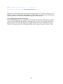
7 Business Process Terminology.............................................................................................. 25
7.1 Business Process ............................................................................................................. 25
7.2 Business Process Management ....................................................................................... 25
7.3 BPM Life-Cycle ............................................................................................................. 25
7.4 Business Process Modeling ............................................................................................ 26
8 The Process Designer Tool ................................................................................................... 27
8.1 The SharePoint Object Model ........................................................................................ 27
8.2 The Web Part Implementation ........................................................................................ 30
8.2.1 Passing data to Silverlight ........................................................................................ 30
8.2.2 Passing data with an XML Data Island .................................................................... 30
8.2.3 The Silverlight Control ............................................................................................ 31
8.3 Drag-and-Drop ................................................................................................................ 31
8.4 Data Binding ................................................................................................................... 33
8.5 Using Styles .................................................................................................................... 34
8.6 Using Control Templates ................................................................................................ 35
9 WCF and Silverlight.............................................................................................................. 37
9.1 Creating a Silverlight enabled Service ........................................................................... 37
9.2 Consuming the Web Service .......................................................................................... 37
9.3 Calling the Web Service ................................................................................................. 37
9.4 WCF and the SharePoint Object Model ......................................................................... 37
9.4.1 The XmlSerializer .................................................................................................... 38
9.5 Error Handling ................................................................................................................ 39
9.6 Other Communication Patterns ...................................................................................... 39
10 The Model-View-ViewModel Pattern ................................................................................ 41
11 Silverlight Testing and Debugging ..................................................................................... 42
11.1 Unit testing ................................................................................................................... 42
11.2 The Silverlight testing framework ................................................................................ 43
11.2.1 Creating a simple test ............................................................................................. 43
11.2.2 Creating UI tests .................................................................................................... 44
12 Result ................................................................................................................................... 47
13 Discussion ........................................................................................................................... 49
14 Conclusion ........................................................................................................................... 50
15 References ........................................................................................................................... 51
Appendix A. User Manual ....................................................................................................... 53
Appendix B. Web Config ......................................................................................................... 59
1 Introduction
Web users today have an increasing demand of using web applications with a richer
experience and with a greater amount of functionality. RIAs (Rich Internet Applications) are
being used everywhere and is gradually replacing HTML applications. Dynamic design in
HTML is accomplished by integrating CSS (Cascading Style Sheets) and scripting languages.
However, HTML does not offer any interactivity and compels multiple page refreshes making
browsing time consuming. RIA’s on the other hand are more robust, visually compelling and
responsive.
Silverlight is a framework released by Microsoft for building RIAs. Silverlight can run on a
variety of devices and desktop operating systems within a browser. When surfing to a page
which contains Silverlight content, the browser will download the Silverlight code and render
the content to the designated place on the page. Silverlight is supposed to offer the user a
richer user experience than the traditional mixture of HTML and JavaScript. The technique is
not new; the most successful browser plug-in is Adobe Flash. The benefits of Silverlight is the
underlying maturity of the .NET programming environment which Flash does not have,
having evolved from being a multimedia player to a programming tool.
SharePoint WSS (Windows SharePoint Services) is another technology released by Microsoft.
It is an information portal that lets people and teams connect, communicate and collaborate.
As companies grow it gets harder to manage the increasing amount of documents and files
that are produced. SharePoint overcomes this issue by allowing the company to store all
documents and files in a central site. Working today often means working on many different
office locations even in other countries. SharePoint lets employees connect and collaborate no
matter where the individual is located.
Being able to develop interactive, user rich and robust applications within a strict business
environment which SharePoint offers has lead to the subject of this thesis. The thesis will
evaluate the benefits of Silverlight when integrated in SharePoint WSS. Any surplus values
will be evaluated in conjunction to what companies and customers gain from the technology.
The thesis will also describe in detail how the integration of Silverlight in SharePoint is
accomplished and describing any problems and difficulties. In conjunction to this report a
Process Designer tool has been implemented and integrated in a SharePoint environment. The
tool has been integrated to get a practical approach to the integration and to be able to
evaluate the technology of Silverlight.
1.1 Background
The thesis has been written at Consignit. Consignit is a consultant company with main office
in Gothenburg. Consignit customers include Volvo, Sweco and AstraZeneca. Their main
business is delivering solutions for Enterprise Content Management, where SharePoint is their
main area of expertise.
SharePoint is often used as the company’s intranet portal where information is gathered in a
central location. Moreover companies often have standardized processes where a collection of
connected activities for describing how to produce a service or product are depicted. To these
processes documents are connected holding detailed information how to accomplish the
activities to the processes. This information is often stored and managed within SharePoint
making SharePoint a good location for central administration of the company’s processes.
1
The process-documents are often not stored in a single location but are rather spread around
the portal making it hard for employees to get a visual picture of the processes as well as
accessing the documents from a central place within the portal. Consignit has thus seen the
need for a tool integrated within SharePoint for designing process hierarchies that the processdocuments can be connected to.
In conjunction to this need Consignit is interested in evaluating any surplus values that
Silverlight brings to SharePoint WSS and to analyze any difficulties and challenges occurring
when doing the integration and the implementation of the Process Designer tool.
1.2 Purpose
The purpose of the thesis is to model, visualize and implement a process-navigation and
designing tool in Silverlight and integrate it on a SharePoint site. By this practical approach
the Silverlight technology can be evaluated when it comes to any surplus values that it brings
to user experience and also how well it cooperates with the SharePoint object model. By a
practical integration any difficulties can be evaluated for future development of other tools.
1.3 Delimitation
The thesis deals with two major areas; Silverlight and SharePoint WSS. Therefore an
introduction of both technologies is given.
The tool that has been integrated is concerning the processes within a company and how these
are structured; a brief overview of different business process terminologies will hence be
outlined.
WCF (Windows Communication Foundation) will be explained in combination with
Silverlight for server client communication. Other server client communication patterns will
be briefly described as a supplement to using WCF.
The tool developed in conjunction to the report will be presented, and how the integration of
the tool is done within a SharePoint site.
Future improvements of the Process Designer tool will be discussed. Implementation oriented
improvements but also potential additions to the tools functionality and graphical user
interface.
An introduction to the Model-View-ViewModel pattern is given that is often used
implementing Silverlight. It is used for decoupling responsibilities between application layers
and for making unit testing easier.
The Silverlight testing framework is discussed with a couple of implementation examples
from the Process Designer tool.
The report will briefly explain Microsoft Office SharePoint Server (MOSS) but will not
dwell into any details concerning the extensions that MOSS is to WSS. WSS is built on top of
ASP.NET; the technology of ASP.NET is beyond the scope of the thesis and is not included.
2
2 The Process Designer Tool an Introduction
Many companies have standardized processes for meeting customer needs. The set of
connected activities that belongs to these processes are often described in a number of
documents. In SharePoint WSS these documents are spread around the intranet portal in
document libraries. Keeping track of which document that belong to what process gets more
and more complicated as companies grow and additional documents are added.
The Process Designer tool is meant to aid employees within the company to get a visual
overview of the processes and which documents that are connected to them. New processes
and links to documents can be added as processes evolve. The user is able to navigate through
a hierarchy of sub processes to get a more detailed view of the building stones of a major
process.
This chapter will give an introduction to the graphical user interface of the application. A
brief functionality overview is also presented. A later chapter will dwell into deeper details
concerning server communication with WCF, working with the SharePoint object model for
interacting with SharePoint document libraries and user groups, and Silverlight specific
implementation techniques.
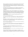
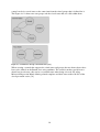
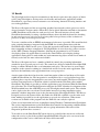
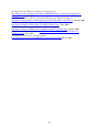
2.1 The Graphical User Interface
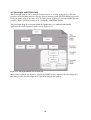
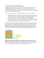
The Silverlight Process Designer tool has been divided into four major presentation areas; a
top toolbar, a tab control to the left, a properties tab control on the bottom and a main
presentation area in the middle where the processes can be dragged and dropped.
Figure 2.1-1 The Process Designer tool
3
The top toolbar consists of four buttons for interacting with the process model; a delete button
for deleting a process, a check in and checkout button for checking in and checking out the
process level in view and a back button to navigate backwards in the process hierarchy.
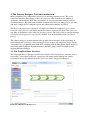
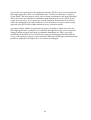
The left tab control consists of a Designer tab and a Viewer tab. In the Designer tab a list box
is used to show the available process figures that can be added to the process model. The
Viewer tab is for navigation purposes. Here a tree control has been implemented that shows
the hierarchy of processes and their activities.
Figure 2.1-2 The Tree View tab
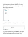
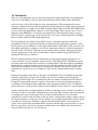
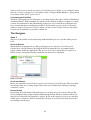
The bottom tab control shows properties to the process level in view. Here there are three
tabs, the first tab is for handling document links connected to the model, the second tab is for
handling metadata values and the last tab shows earlier versions of the process level. Within
all tabs list box controls are being used for presenting the information.
Figure 2.1-3 The Version History tab
On the main presentation area the processes are dragged and dropped. On each corner process
level relevant data is displayed. In the top left corner the SharePoint user group is shown that
is responsible for the process level. On the top right the current version of the process level is
shown. On the bottom left corner the user is informed of which process that has been clicked
and is currently in focus and on the last corner the process levels name is displayed.
4
2.2 Functional Overview
2.2.1 User Group and Process Owners
The Silverlight application makes use of the SharePoint user groups for dividing users in two
main categories. When a user belongs to the owner user group of a process level the user has
designer rights otherwise navigation rights. The users having designer rights can add, delete
and edit processes. Users with navigation rights can only navigate through the part of the
processes hierarchy tree where he does not belong to the owners group of the process level.
By making use of the SharePoint user groups, the management of these groups can be kept
within SharePoint. If a user needs to have designer rights to a certain process he can easily be
added from the SharePoint user interface by a user with the right permission.
2.2.2 Checking in and out of Processes
The Silverlight tool makes use of a SharePoint document library for saving the process levels
within the process hierarchy. It therefore also inherits the SharePoint functionality of being
able to check in and out process levels. Before any changes can be made to the level, it has to
be checked out to make sure that no other user within the owner group is working with the
processes. When the user has finished editing, the process level he can check in his work. If
not checked in it will be locked for all others for editing.
2.2.3 Versioning
In SharePoint an additional versioning feature can be added to any document library. This is
to keep a history of documents as they evolve over time. The versioning is also used for
triggering workflows.
The Process Designer tool makes use of the versioning by giving the designers the possibility
to check in their work as a minor or major version. With the separation of minor and major a
workflow can be designed within SharePoint that is triggered when the designer of a process
level decides to make his changes public by checking them in as a major version. The
workflow can be to send an email message to all users within the same user group that a
major version has been created or to all other users within the portal that new processes can be
viewed.
2.2.4 Process Visibility
The visibility of the processes and their activities are linked to both the versioning and the
user groups.
Firstly a process is visible for any user that is part of the owner user group for that process.
The sub process level of the process can be made public and therefore visible for others by
checking it in as a major version. As long as it is a minor version it will only be seen by its
owners.
An additional feature lets the designer select one or more groups that will see the processes
when the level is checked in as a major version keeping it hidden for others. As default all
user groups will see the major version.
5
3 Windows SharePoint Services
Windows SharePoint Services (WSS) provides capabilities to meet business needs such as
managing content and business processes. This simplifies how people find and share
information within a company. [1]
3.1 WSS and Microsoft Office SharePoint Server 2007
Microsoft Office SharePoint Server (MOSS) 2007 is built on top of WSS 3.0 which is further
built on top on services provided by Microsoft Windows Server 2003. The main platform use
the Microsoft .NET 2.0 Framework. MOSS is provided by several technologies; Internet
Information Service for hosting Web applications, ASP.NET 2.x which support master pages,
content pages, Web Parts and personalization. [9]
MOSS 2007 relies on WSS technology to provide a consistent, familiar framework for lists
and libraries, site administration, and site customization. Any feature that is available in WSS
is also available in MOSS.
MOSS offers additional features that are unavailable in WSS. For example, both MOSS and
WSS include site templates for collaborating with colleagues and setting up meetings.
However, MOSS includes a number of additional site templates related to enterprise and
publishing scenarios. [1]
3.2 WSS Site Provisioning
WSS was designed to create Web sites in a fast manner. The architecture was designed to
work in a Web farm environment. Creating a site can be done by any person within the IT
Department by filling out the required information needed in a web-browser form and
clicking OK. There is no need for a system developer to create a website and no need for an
administrator to copy any files to an application server. The WSS provisioning engine
cooperates with an integrated storage model that uses several SQL Servers to store content
and configuration data. [2]
In this way users can easily design web sites with shared elements such as contact lists and
document libraries. Because of the site provisioning engine it is easier to manage thousands of
Web sites making them accessible to tens of thousands of users. This is achieved with the
Web-farm architecture in mind making WSS very scalable. The architecture is based on
stateless front-end Web server that relies on back-end SQL-Servers for storing content and
configuration data. [3]
3.3 WSS Farm
A farm is a set of one or more servers that provides WSS functionality to its clients. In its
simplest form it consists of a single computer that acts as both a front end Web server and an
SQL Server managing WSS content. A more complicated farm consists of dedicated SQL
Servers and several front-end servers. Each farm has a configuration database that keeps track
of important information concerning the farm environment. E.g. what front-end servers are
associated with the farm and what users have administrative permissions on farm level. [2]
3.4 Databases
WSS relies on two different kinds of databases, one configuration database and content
databases. The configuration database holds deployment-specific information for each Web
server, IIS server and WWS Web site. The content database holds data associated with WSS
Web sites.
6
Each content database stores information of one or more WSS Web sites. The data is stored
on a site-by-site basis with information concerning lists, documents, site customization and
personalization. The fact that the information concerning one site is stored on one SQL Server
makes it easier for back-up and restoring WSS sites when necessary. [4]
3.5 Internet Information Service
WSS is built on Internet Information Service (IIS) and relies on IIS Web sites to handle
incoming HTTP requests. An IIS Web site is an entry point to the IIS Web server
infrastructure. The default web site that IIS creates listen to port 80, additional Web sites can
be created that listen to other ports.
One important feature with IIS Web sites is that the security settings can be configured
differently for different Web sites. One Web site might use Basic Authentication and allowing
anonymous access. Another site may be used as an intranet site and can therefore be
configured to require integrated Windows authentication and to disallow anonymous access.
[2]
In WSS terms an IIS Web site is called a virtual server. A virtual server has to be extended
with WSS to be able to run WSS Web sites. When installing WSS it automatically extends the
default Web site listening to port 80. With SharePoint Central Administration other Web sites
can be extended to support WSS.
Unlike ASP.NET, WSS does not configure each Web site using a Virtual directory. WSS
instead looks for all the configuration information in the configuration database and content
database. This means that when starting creating WSS sites they will not appear in the IIS
metabase. Therefore IIS will not know how many WSS Web sites it is hosting. Because WSS
does not need a new virtual directory for each Web site the scalability and maintenance is
improved. When WSS extends the virtual server it installs an ISAPI filter which intercepts
each request and determines if it should be handled by IIS or WSS. [4]
3.6 Site and Site Collections
A WSS site stores lists, document libraries and child sites. The site has securable entities
which content is only visible for a set of defined users. These set of users can be defined
either on the site itself or be inherited from the parent site. A set of groups and permissions
can also be configured for the site which defines the level of accessibility on lists and
documents libraries.
WSS relies on IIS and the ASP.NET authentication provider infrastructure for user
authentication. When it comes to user authorization WSS provides user interface components
that allow privileged users to configure authorization to different elements within a site.
A WSS site provides a fully customizable and extendable user interface. The site
administrator can create pages and customize them. The administrator can even change the
navigation structure using the browser.
A WSS site also uses Microsoft Web Part technology. A site administrator can customize
Web Part pages by configuring and adding Web Parts. A user can then personalize the Web
Parts by modifying them. The data needed for showing the Web Parts in a customized manner
is saved automatically in the content database.
7
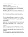
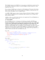
A site has to be provisioned within an existing Web application. The site cannot exist on its
own within the Web application. Instead, each site has to be inside the scope of a site
collection. A site collection works as a container for WSS sites. Each site collection must
have a top-level site. The collection can then further contain a hierarchy of child sites. [2]
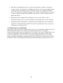
Figure 3.6-1 Site Hierarchy [9]
3.7 Web Parts
As mentioned earlier a Web Part makes it possible for a site owner to customize site pages
with changes that is made visible for users. A user can then personalize these Web Parts; the
changes made by the user will then only be seen by the individual user himself. [2]
The difference between an ordinary ASP.NET page and a Web Part page is that ASP.NET
pages are stored as a text file in the file system of the Web server. The parts needed for a Web
Part are stored in multiple tables in the WSS content database. This makes it possible to
personalize and customize Web Parts for different sites and users.
A Web Part page has several Web Part Zones. A Web Part is added to the page by placing it
in a zone. [8]
8
4 Silverlight 2.0
Silverlight is a framework for building browser hosted applications that can run on several
operating systems. Silverlight runs as a browser plug-in, which means that when surfing to a
page containing Silverlight content the browser will download, execute the code and render
the content to the designated place on the page. Silverlight provides a richer user experience
when used properly than the traditional mixture of HTML and JavaScript.
The technique is not unique, similar technologies exist that use the same browser plug-in
concept. Most successful of them all has been Adobe Flash. Because Flash has just recently
gone from being a multimedia player to a set of programming tools, it lacks the mature
programming environment like .NET.
This is where Microsoft has seen the advantage in Silverlight offering cross-platform support
like Flash but also offering development in the mature environment of .NET. Silverlight has
also architectural benefits to Flash the most significant one is that its base is a thinner version
of .NET’s common language runtime. This makes it possible for a developer to write
Silverlight code using C# or Visual Basic. [10]
4.1 Silverlight and Windows Presentation Foundation
Silverlight uses the model WPF has for building client-side user interfaces. WPF is the
successor of Windows Forms and is the next generation of creating Windows applications.
WPF was first introduced with .NET 3.0. WPF not only makes development of Windows
applications easier but also boosts performance by rendering everything through a DirectX
pipeline.
Silverlight can’t use all of the features available in WPF. Many of WPF’s features rely on
Windows-specific display drivers which makes them impossible to use within Silverlight,
because of the fact that Silverlight is operating system independent. But rather to invent a
whole new model for Silverlight it uses a subset of the WPF features. This makes them very
similar to each other. Here is a listing of some of the similarities:
•
•
•
•
•
Defining a user interface is done in the markup language XAML.
The same syntax can be used when binding data to controls.
Silverlight uses the same basic controls as WPF.
Style and template syntax are similar.
Drawing 2D graphics.
In future releases even more of the features available in WPF will be found in Silverlight. [11]
9
4.2 Silverlight and HTML DOM
The Silverlight plug-in can be integrated with any new or existing web property. The web
property can be anything from a web page, blog or intranet portal. The Silverlight plug-in can
fill up the whole page or just parts of it. It can be placed anywhere it is wanted within the web
property. This is possible because of its relationship with HTML DOM.
The Silverlight plug-in is integrated with the DOM. Once it is embedded the DOM
application tree will expand as can be seen in Figure 4.2-1.
Figure 4.2 1 Silverlight DOM model extension [12]
Most of the available web browsers support the DOM variants supported by Silverlight. It is
therefore possible for Silverlight to be a platform independent plug-in.
10
4.3 The Silverlight Object Model
The Silverlight Object Model is much like the tree structure of the HTML DOM model. The
tree is represented in a Silverlight XAML file. Each file has child elements that represent the
UI. The rendering is done recursively in order from left to right. The rendering is shown in
Figure 4.3-1.
Figure 4.3-1 Silverlight Rendering order [12]
The ordering of the rendering is important for in what order the elements are displayed.
Elements that are rendered later are shown on top of earlier rendered elements. The Silverlight
Object Model extends the HTML Document Object Model. But it is not possible to access
Silverlight elements from the DOM model. This has to be done from within the Silverlight
plug-in.
4.4 XAML
Extensible Application Markup Language or short XAML is a markup language to instantiate
.NET objects in XML format. Similar to the role of HTML, XAML lets one easily visualize
elements in a hierarchal fashion and at the same time separating the content from code.
Separating the code is possible because each XAML element corresponds to a .NET type.
And each attribute to the element corresponds to a .NET property. The short example below
illustrates this.
XAML
<TextBlock Text="Hi there!" FontFamily="Times New Roman" />
C#
Visual Basic
TextBlock tb = new TextBlock();
tb.Text = "Hi there!";
tb.FontFamily = "Times New Roman";
Dim tb as New TextBlock
tb.Text = "Hi there!"
tb.FontFamily = "Verdana"
11
The TextBlock element in the XAML code corresponds to an initialization statement in C# or
in Visual Basic. Each time an element is created in XAML the default constructor is called
behind the scenes. [12]
Every element in XAML maps to an instance of a Silverlight class. The name of the element
maps exactly to the name of the class. For example the <TextBlock> element from the code
above instructs Silverlight to create a TextBlock object.
As in XML, XAML supports nesting of elements. Having a Grid inside a Button is perfectly
legal. Nesting is though often used as containment where usually the case is having a Grid
that has Buttons within it.
Attributes can be set to each element, from the code example above Text and FontFamily are
attributes to the TextBlock element. [11]
4.5 Code behind
To each XAML page there is a belonging code-behind page much like ASP.NET pages.
Having code-behind pages is a good way to separate code from UI related code. XAML code
is stored in files with file suffix .xaml and the code-behind files with the suffix .xaml.cs. The
reference to the code-behind file in the XAML file is through the x:Class attribute. The class
definition is compiled and stored in an assembly and placed in a directory relative to the
application called ClientBin. The class definition is used for handling events that are triggered
from the user interface which are defined in the XAML file. As shown below the Loaded
attribute has an event-handler method specified for it. The compiler will expect that there is a
method with the same name in the code-behind code. [12]
Page.xaml
<UserControl x:Class="XAML01.Page"
xmlns="http://schemes.microsoft.com/winfx/2006/xaml/presentation"
xmlns:x="http://schemes.microsoft.com/winfx/2006/xaml"
Loaded="UserControl_Loaded" Width="400" Height="300">
<Grid x:Name="LayoutRoot" Background="White">
</Grid>
</UserControl>
Page.xaml.cs
using System.Windows.Controls;
namespace XAML01
{
public partial class Page : UserControl
{
public Page()
{
InitializeComponent();
}
private void UserControl_Loaded(object sender,
RoutedEventArgs e) { }
}
}
12
4.6 UI Class Hierarchy
Silverlight has a set of standard controls e.g. list boxes, check boxes, text blocks and others.
These controls are for building user interfaces. But how these are placed on the user interface
is handled by the layout controls (Panels). There is a set of base functionality that every
control in Silverlight offers. Figure 4.6-1 shows a shortened class diagram with a subset of
controls. To be noticed is that not all elements are user interface controls.
Figure 4.6-1 Silverlight control class hierarchy [21]
4.6.1 DependencyObject
The root of all visual elements is the DependencyObject class. This gives the ability to
interact with dependency properties. The dependency properties are special types of
properties that back the .NET property. The value of a dependency property depends on
multiple sources and therefore the .NET property is not enough. Its value can come from data
binding, animation, templates, styles or local values.
4.6.2 UIElement
The UIElement represents a visual component, and gives all elements that inherit from it the
ability to draw themselves on a user interface. The UIElement supports a number of methods,
properties and events.
4.6.3 FrameworkElement
The FrameworkElement adds additional features to the UIElement class like object lifetime
events and data binding support. It is the direct base of the Panel and the Control class which
are the base classes for most controls and for object positioning.
13
4.6.4 Layout Controls
Silverlight provides three layout controls for positioning visual objects and other controls on
the user interface; the Canvas the Grid and the StackPanel. These controls all inherit from the
Panel class. The Canvas has the ability to place a child element to an absolute position. The
Grid uses a tabular configuration with rows and columns for placing the elements and the
StackPanel places its child controls next to each other either horizontally or vertically. Layout
controls can be nested for example having a Grid within a Grid. [21]
4.7 Silverlight Application Architecture
Two XAML files are by default part of a Silverlight project.
•
•
App.xaml, which is used to define styles and resources. The corresponding codebehind file is used for initialization and cleanup code.
Page.xaml is the startup control that is shown when the plug-in is loaded. Here the
user interface of the application is defined either by self created controls or Silverlight
controls.
4.7.1 The Silverlight XAP File
The result of building a Silverlight project is a compressed file with the extension .xap. It
contains compiled XAML and code-behind, an application manifest file and one or more
assemblies containing Silverlight controls that are used by the application.
4.7.2 Testing a Silverlight Application
When creating a Silverlight project a dynamically created HTML page can be included for
testing purposes. A TestPage.html is created when the application is built. The object tag
communicates with the plug-in and asks it to download and execute the XAP file defined with
the source parameter. [16]
<div id="silverlightControlHost">
<object data="data:application/x-silverlight," type="application/xsilverlight-2" width="100%" height="100%">
<param name="source" value="HelloWorld.xap"/>
<param name="onerror" value="onSilverlightError" />
<param name="background" value="white" />
<a href="http://go.microsoft.com/fwlink/?LinkID=115261" style="textdecoration: none;">
<img src="http://go.microsoft.com/fwlink/?LinkId=108181"
alt="Get Microsoft Silverlight" style="border-style: none"/>
</a>
</object>
<iframe style='visibility:hidden;height:0;width:0;border:0px'></iframe>
</div>
14
5 Windows Communication Foundation
Windows Communication Foundation (WCF) is a set of APIs for creating distributed
applications that can communicate with each other. The same set of APIs is used when two
different applications communicate on the same computer or over the Internet.
5.1 Messaging and Endpoints
WCF is based on communication with messages. Therefore anything that can be formed as a
message can be represented in the programming model.
The communication model separates clients which initiate the communication and services
which are waiting and responding to the client’s request.
The client and service communicate using endpoints. The service defines a set of endpoints
which is all information that is necessary for exchanging messages. The client will then
generate an endpoint that is compatible with the service endpoint.
An endpoint is a standard description of how a message should be sent and how the message
looks like. This is done by letting the service expose metadata to the client. [13]
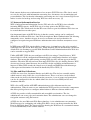
5.2 Services and Clients
A service can be both local and remote, and the client consuming the service can be literally
anything – a Windows Forms class, an ASP.NET page or another service. All messages in
WCF are SOAP messages. The messages are independent of transport protocol, unlike Web
services WCF can communicate over a set of protocols not only HTTP.
Figure 5.2-1 WCF proxy model [14]
The client will never communicate with the service directly not even when run on the local
machine instead a proxy is used to forward the call to the service. The proxy exposes the same
methods as of the service. This programming model approach is good for making the location
of the service transparent. It enables the possibility to switch service location without
affecting the client but also simplifies the application programming model. [14]
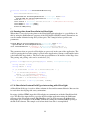
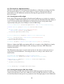
5.3 Setting up a Service
When setting up WCF for communication an address, a binding and a contract is needed.
With this information either a service-side endpoint can be created which the client will
access or a client-side channel which the client will use to communicate with the service.
15
WCF services are setup in three steps. First, create a service contract with one or more service
contracts. Second, create the service contract implementation. Third, configure the host with
an endpoint to the service.
An example service contract with one operation contract is specified below. The service
contract is a .NET interface with the System.ServiceModel.ServiceContractAttribute attribute
applied to it. The operation contracts are simple method signatures.
using System;
using System.ServiceModel;
//+
namespace Contact.Service
{
[ServiceContract(Namespace = Information.Namespace.Contact)]
public interface IPersonService
{
//- GetPersonData -//
[OperationContract]
Person GetPersonData(String personGuid);
}
}
A good practice is to keep the WCF service interfaces short, between 3 to 7 methods per
contract. The namespace property is for logically organizing services much like how the .NET
namespace works for separating classes and interfaces.
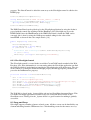
The GetPersonData operation contract has a Person as return value. Person is a data contract.
Data contracts are classes which have the
System.Runtime.Serialization.DataContractAttribute attribute applied to them with one or
more private or public data members.
[DataContract(Namespace = Information.Namespace.Contact)]
public class Person
{
//- @Guid -//
[DataMember]
public String Guid { get; set; }
//- @FirstName -//
[DataMember]
public String FirstName { get; set; }
//- @LastName -//
[DataMember]
public String LastName { get; set; }
}
Above is an example of a Person data contract. It is important to keep in mind only to specify
as many members as is needed. Because all information is sent over a wire the amount of data
can affect performance. When it comes to Silverlight this is even more important. Firstly, the
information that is sent has to be delegated through a browser before the plug-in can process
it. And secondly, the more information that has to be sent over the wire the more
unresponsive the Silverlight application gets.
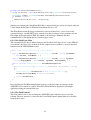
16
The second step is to create an implementation to the contract. The implementation is put in
an ordinary class as shown below.
using System;
namespace Contact.Service
{
public class PersonService : Contact.Service.IPersonService
{
//- @GetPersonData -//
public Person GetPersonData(String personGuid)
{
return new Person
{
Guid = personGuid,
FirstName = "John",
LastName = "Doe"
};
}
}
}
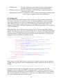
Step three is to configure the host of the service with the corresponding endpoints. This is
done by creating a Person.svc file. The below line of code is added in the file which specifies
the service implementation.
<%@ ServiceHost Service="Contact.Service.PersonService" %>
In addition the service host in itself has to be configured. It is done by declaring a service and
adding it to the endpoint. The declaration is done in the service web site’s web.config file.
The entire file looks as shown below.
<?xml version="1.0" encoding="UTF-8"?>
<configuration>
<system.serviceModel>
<services>
<service name="Contact.Service.PersonService">
<endpoint address="" binding="basicHttpBinding"
contract="Contact.Service.IPersonService" />
</service>
</services>
</system.serviceModel>
</configuration>
The configuration says that there can be “basicHttpBinding” communication through the
Contact.Service.IPersonService at address Person.svc to Contact.Service.PersonService. [15]
17
6 Integrating Silverlight in SharePoint
6.1 Visual Studio Configuration
A couple of extensions have to be downloaded for Silverlight 2.0 to work properly in the
development environment.
•
•
•
Download and install the Silverlight 2.0 browser plug-in.
Download and install Visual Studio 2008 Service Pack 1 and .NET Framework 3.5
Service Pack if not already installed on the system.
Download and install Microsoft Silverlight 2 Tools for Visual Studio 2008.
6.2 SharePoint Runtime Configuration
For SharePoint to be able to host Silverlight applications a couple of steps have to be taken.
•
•
•
•
•
The .NET 3.5 Framework has to be installed on the SharePoint Web front-end.
When hosting Silverlight in WSS, Windows SharePoint Services 3.0 with service
Pack 1 has to be installed. If hosting the Silverlight application in MOSS, MOSS 2007
Service Pack 1 has to be installed.
The System.Web.Silverlight.dll assembly has to be deployed in the GAC. This dll is
part of the Silverlight 2 SDK.
The IIS hosting the SharePoint sites has to be extended. This is done by registering the
XAP MIME type in the IIS Manager.
The web.config file of the targeted Web application has to be extended with a number
of configuration elements. Please see Appendix A for the extensions that have to be
made to the web.config file. [16]
18
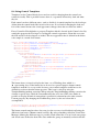
6.3 Integrating Silverlight in a SharePoint Web Part
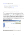
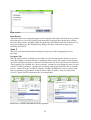
One way of creating a Web Part project for SharePoint is to use the Visual Studio Extension
for Windows SharePoint Services 3.0. The extension contains a project template which has
the initial infrastructure and a list of referenced assemblies. It also contains a WSS 3.0 Feature
for advertising the Web Part in a SharePoint site collection. In addition a Web Part class is
created and the possibility to edit the SharePoint solution (WSP file) which is generated when
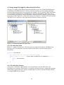
the project is built. Figure 6.3-1 shows how the project template is structured in Visual Studio.
The WSP View is depicted on the right and the Solution is shown to the left.
Figure 6.3-1 Visual Studio WSP and Solution View
6.3.1 The Web Part Class
Below is a sample web part class. The web part has to inherit from the base WebPart class.
Here the code is located that is executed when the Web Part is activated and loaded in
SharePoint.
namespace HelloWorld
{
[Guid("d359c723-89b0-4224-8d30-ee4f72898c4f")]
public class HelloWorld : System.Web.UI.WebControls.WebParts.WebPart
{
public HelloWorld()
{
}
}
}
6.3.2 The Web Part Feature
To advertise a Web Part a WSS Feature is used, the Feature adds the Web Part to the
SharePoint site collection. The Feature is an xml file with the extension .webpart that contains
information regarding the class and the assembly that is needed to load the Web Part. Below
is a sample XML file of a Feature.
19
<?xml version="1.0" encoding="utf-8"?>
<webParts>
<webPart xmlns="http://schemas.microsoft.com/WebPart/v3">
<metaData>
<type name="d359c723-89b0-4224-8d30-ee4f72898c4f" />
<importErrorMessage>Cannot import HelloWorld Web
Part.</importErrorMessage>
</metaData>
<data>
<properties>
<property name="Title" type="string">Silverlight Web
Part</property>
<property name="Description" type="string">A sample</property>
</properties>
</data>
</webPart>
</webParts>
6.3.3 The Element Manifest File
The WSP also contains an element manifest file for the Feature. This XML file is executed
when the Feature is activated. It is constructed by two elements; the module element which
has information about where the destination library is located and the file element which has
information about the actual file that is put in the Web Part gallery.
<Elements Id="d359c723-89b0-4224-8d30-ee4f72898c4f"
xmlns="http://schemas.microsoft.com/sharepoint/" >
<Module Name="WebParts" List="113" Url="_catalogs/wp">
<File Path="HelloWorld.webpart" Url="HelloWorld.webpart"
Type="GhostableInLibrary" >
<Property Name="Group" Value="Silverlight in
SharePoint"></Property>
</File>
</Module>
</Elements>
6.3.4 The Feature File
The solution also contains a feature.xml file which holds metadata regarding the Feature that
is advertising the Web Part.
<Feature Id="d3432223-787e-461f-82df-2bca9882e3f4"
Title="Silverlight 2 Hello World Web Part Feature"
Description="Sample Silverlight Web Part
for SharePoint"
Scope="Site" Version="1.0.0.0" Hidden="FALSE"
DefaultResourceFile="core"
xmlns="http://schemas.microsoft.com/sharepoint/">
<ElementManifests>
<ElementManifest Location="HelloWorld\HelloWorld.xml" />
<ElementFile Location="HelloWorld\HelloWorld.webpart" />
</ElementManifests>
</Feature>
6.3.5 The SharePoint Solution File
The actual deployment of the Web Part assembly and the Feature files is done by the
SharePoint Solution file. The file with the extension .WSP is a CAB file which contains the
folder structure with all the solution components that is needed to deploy the solution to the
front-end Web servers.
20
<Solution SolutionId="15c907cc-651b-4c52-86ac-db5ec04097e3"
xmlns="http://schemas.microsoft.com/sharepoint/">
<FeatureManifests>
<FeatureManifest Location="HelloWorld\feature.xml" />
</FeatureManifests>
<Assemblies>
<Assembly Location="HelloWorld.dll"
DeploymentTarget="GlobalAssemblyCache" />
</Assemblies>
</Solution>
6.3.6 Hosting Silverlight in the Web Part
To be able to host the Silverlight plug-in in the Web Part a couple of steps have to be taken.
Two assemblies need to be referenced in the Web Part project. Firstly the
System.Web.Extensions.dll contains ASP.NET AJAX 1.0 extension layer. And secondly
System.Web.Silverlight.dll which contains the Silverlight server-side ASP.NET control.
A ScriptManager is required by the Silverlight ASP.NET control to be able to access the
ASP.NET AJAX 1.0 script library. There can only be one instance of the ScriptManager on
the page, therefore a check is done before creating it. By overriding the OnLoad method of
the base class the below piece of code adds the ScriptManager to the page.
protected override void OnLoad(EventArgs e)
{
base.OnLoad(e);
ScriptManager sm = ScriptManager.GetCurrent(this.Page);
if (sm == null)
{
sm = new ScriptManager();
Controls.AddAt(0, sm);
}
}
The XAP file created when building a Silverlight project containing the files and assemblies
that are needed to execute the Silverlight application within SharePoint can be downloaded
from a number of different locations. The example here uses a SharePoint document library
named XAPS to store it. By adding a Module element to the Element Manifest file SharePoint
is told to place the XAP file in the XAPS library when the Feature is activated. When any
changes are being done to the Silverlight application the only thing that has to be exchanged
is the XAP file, which can be done in SharePoint itself. The Feature doesn’t have to be
activated again. Below is the module element that has to be added to accomplish this.
<Module Url="XAPS" RootWebOnly="TRUE">
<File Path="HelloWorld.xap" Url="HelloWorld.xap"
Type="GhostableInLibrary"></File>
</Module>
The last step is to create a child control for the Web Part which will create an object tag that
tells the Silverlight plug-in to download and execute the XAP file. By overriding the base
class method CreateChildControls the Silverlight ASP.NET control can be created. The
Source property specifies where the XAP file is located for download. [17]
21
protected override void CreateChildControls()
{
base.CreateChildControls();
System.Web.UI.SilverlightControls.Silverlight ctrl = new
System.Web.UI.SilverlightControls.Silverlight();
ctrl.ID = "HelloWorld";
ctrl.Source = SPContext.Current.Site.Url + "/XAPS/HelloWorld.xap";
ctrl.Width = new Unit(400);
ctrl.Width = new Unit(300);
Controls.Add(ctrl);
}
6.4 Passing data from SharePoint to Silverlight
When there is a need of passing data to the Silverlight application there is a possibility to do
this by using the InitParameters property of the Silverlight ASP.NET control. Parameters are
sent in comma-delimited string of key/value pairs. The example below specifies two
parameters.
System.Web.UI.SilverlightControls.Silverlight ctrl = new
System.Web.UI.SilverlightControls.Silverlight();
ctrl.InitParameters = "webURL=" + SPContext.Current.Web.Url +
",siteURL=" + SPContext.Current.Site.Url;
The parameters that are passed to Silverlight are processed in the start of the application. The
code for parsing the key/value string is placed in the Application_Startup event handler in the
code-behind file App.xaml.cs. The data is then passed further to an instance of the Page class.
The parsing and passing code can be seen below. [18]
private void Application_Startup(object sender, StartupEventArgs e)
{
string siteurl = null;
string weburl = null;
if (e.InitParams != null && e.InitParams.Count > 0)
{
if (e.InitParams["webURL"] != null)
weburl = e.InitParams["webURL"];
if (e.InitParams["siteURL"] != null)
siteURL = e.InitParams["siteURL"];
}
this.RootVisual = new Page(siteURL, webURL);
}
6.5 A SharePoint Custom Field Type interacting with Silverlight
A SharePoint field type is used to define columns in lists and document libraries. But can also
be used when developing rich survey animations.
By using a hidden HTML input field Silverlight can communicate with the SharePoint field
type. The ID of the input field is passed to the Silverlight application using the InitParams
property of the Silverlight control. The HtmlPage class is used to access the hidden field.
Silverlight gets a reference to the HTML element by calling the GetElementById passing it
the ID of the element. The sample code below shows how this is accomplished.
22
private void SetValueInHiddenControl()
{
string valuestring = this.SelectedValue.ToString(CultureInfo.InvariantCulture);
HtmlElement element = HtmlPage.Document.GetElementById(valueControlId);
if (element != null)
{
element.SetAttribute("value", valuestring);
}
}
Similar to developing the SharePoint Web Part a custom field type can be developed using the
Visual Studio Extensions for Windows SharePoint Services 3.0.
The SharePoint custom field type architecture consists of three files; a core class for the
custom field type, an ASP.NET server control class that is acting as a host container for the
Silverlight application and an XML file which is the field type definition file that
communicates to SharePoint that an extra field type exists.
6.5.1 The Field Type Class
The custom field type has to inherit from one of the built in field type classes or the SPField
class which is the base class of them all. In the sample below a number is stored it therefore
inherits from the SPFieldNumber class.
public class SliderControlField : SPFieldNumber
{
public SliderControlField(SPFieldCollection fields, string fieldName)
: base(fields, fieldName) { }
public SliderControlField(SPFieldCollection fields, string typeName,
string displayName) : base(fields, typeName, displayName) { }
public override BaseFieldControl FieldRenderingControl
{
[SharePointPermission(SecurityAction.LinkDemand, ObjectModel = true)]
get
{
BaseFieldControl fieldControl = new SliderFieldControl();
fieldControl.FieldName = this.InternalName;
return fieldControl;
}
}
}
By overriding the FieldRenderingControl property of the base class an instance of the
ASP.NET server control is created. This will tell SharePoint to display the Silverlight
application using the custom field type.
6.5.2 The Field Control
The field control class is for rendering the ASP.NET control when the user creates the
column. The user interface is created in the CreateChildControls method that is overridden
form the base class.
23
public class SliderFieldControl : NumberField
{
protected override void CreateChildControls() { }
}
Within the CreateChildControls method the Silverlight control is created in exactly the same
manner as when overriding the same method in the Web Part class shown earlier. Passing any
needed parameters is done with the InitParams property of the control.
6.5.3 Deploying a Custom Field Type
The SharePoint field types are compiled in an assembly and deployed in the global assembly
cache. Using an XML file SharePoint is informed of the new type. By using the generation
functionality of Visual Studio Extensions for WSS 3.0 this file can be dynamically created.
The file is deployed under the 12\Template\XML folder with the file prefix .fldtypes. [20]
24
7 Business Process Terminology
7.1 Business Process
A business process is a collection of connected activities that produce a service or product that
meet the needs of a customer. A business process is vital to any organization and generates
revenue and represents a significant part of the cost for the company. There are three kinds of
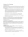
business processes.
• Management processes. These processes oversee the operation of the system. Typical
management processes include Corporate Governance which is the set of processes,
policies, laws and institutions affecting the way a corporation is directed and
administered. Another management process is Strategic Management which is the
ability to formulate, implement and evaluate cross-functional decisions that will
enable an organization to achieve its long-term goals.
•
Operational processes are processes that represent the core business. Typical
operational processes are Purchasing, Manufacturing, Sales and Marketing.
•
Supporting processes. These processes support the core processes. I.e. Accounting,
Recruitment and Technical support.
A typical process starts with a customer need and ends with the fulfillment of this need. A
business process is often divided into sub-processes which have their own attributes.
Analyzing business processes includes mapping sub-processes belonging to a business
process down to an activity level, focusing only on the activities that are needed to
accomplish the process. [7]
7.2 Business Process Management
BPM was from the beginning mostly focusing on the automation of mechanistic business
processes; it has evolved and extended to integrate human-driven processes in which humans
interact with the mechanistic processes. Normally steps in a business process that are
performed by humans are assigned to the appropriate people of an organization (similar to
workflow systems).
7.3 BPM Life-Cycle
The BPM life-cycle splits the activities in BPM in five categories: design, modeling,
execution, monitoring and optimization.
• Design. Identification of existing and future processes is an essential part in this lifecycle category. Here focus lies on representing the flow of the workflow and
determining which actors are participating. A good design is important for reducing
the problems over the lifetime of the process.
•
Modeling. The modeling stage in the cycle takes the design into account and
introduces a set of variables, I.e. when there are changes in the cost of materials that
can change how the process operates under different scenarios.
25
•
Execution. Automating the process can be done by having a software system that
executes all the steps in the process. Human interaction can also be used though often
resulting in more complicated system. Software systems are available that lets the
process be defined in a computer language. The system will communicate via services
to remote applications that perform business operations or when to complex ask for
human interaction.
•
Monitoring. Here tracking of the running processes are done. This to collect
information of the processes state and statistics of the performance can be evaluated.
•
Optimization. Here information is collected from the monitoring step to identify the
potential or actual bottlenecks, which is then used to optimize processes in respect to
saving time or saving costs. [6]
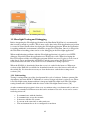
7.4 Business Process Modeling
The purpose of this activity is to represent the processes of an organization. These models can
then be changed to improve the efficiency and quality of the process. A graphical
representation of business process information is an effective way for presenting the processes
to business stakeholders. The stakeholders are represented by; the business analyst who
creates and optimizes the processes, the developer that implements the processes, and the
business manager who monitor and manage the processes. For these visual languages such as
the Business Process Modeling Notation and the Unified Modeling Language are used. [5]
26
8 The Process Designer Tool
The Process Designer tool that has been developed and integrated in SharePoint uses the same
basic integration steps that are described in a previous chapter with some minor
modifications. It is integrated as a Web Part that communicates with SharePoint WSS via a
WCF service. This chapter will describe the WCF communication pattern that has been used
but also other approaches that can be used for the interaction between the client plug-in of
Silverlight and the server side of SharePoint.
The direct communication with SharePoint WSS is done through the WSS object model. The
object model is accessed in the implementation of the WCF service as well as in the Web Part
class that initializes the Silverlight control. Some basic issues when programming against the
object model for accessing lists, document libraries and user group information will be taken
into consideration.
Silverlight make use of some powerful implementation patterns for data binding and when
using styles and templates. By using styles the work of the GUI designer and the web logic
programmer can be separated. A number of out-of-the box controls are shipped with
Silverlight, the controls that have been used will be described.
8.1 The SharePoint Object Model
WSS consists of a server-side object model that makes it easier for the developer to access
objects that represent different items of a SharePoint Web site. A hierarchy of objects is
available which makes it easy to access objects on lower levels.
Depending on the application that is created different entry points to the object model can be
used to start from. For example, when customizing administration and configuration for
deployment the static ContentService property can be used to get the current Web service
object and its collection of Web applications. Or when modifying settings in the
administrative Web application the AdministrationService property is used.
When developing a Web Part or Web application and within them working with site
collections, individual sites or lists the SPContext class can obtain this information. When a
Web application is created and put in the /_layouts virtual directory the functionality is
available to all sites on the Web server. Outside an HTTP context a constructor of the SPSite
class has to be used to get specific site collections and objects within it.
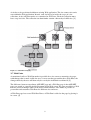
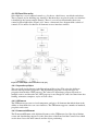
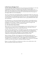
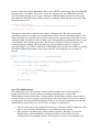
Figure 8.1-1 shows the WSS server architecture in relation to the available objects of the
Microsoft.SharePoint.Administration namespace.
27
Figure 8.1-1 WSS Server Architecture [22]
1. The SPFarm object is located on the highest level of the WSS object model. The Servers
property gets a collection of all deployed servers and the Services property gets a
collection of all the services.
2. Each SPServer object represents each server computer within the server farm. The
ServiceInstances property gets each service instance on the computer.
3. Each SPService object represents a service or application that is installed on the server
farm.
4. SPWebService object provides access to configuration settings for a service or an
application.
5. The SPDatabaseServiceInstance object represents a single instance of a database service
running on the server or application.
6. The SPWebApplication is representing each of the Web applications in the IIS; it
provides credentials and other server farm wide application settings.
7. The SPContentDatabase represents a database that contains data for the SharePoint Web
Application.
8. The SPSiteCollection represents the site collection within the Web application.
28
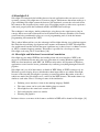
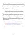
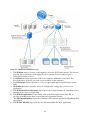
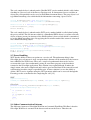
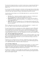
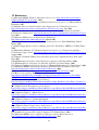
The WSS site architecture is shown in Figure 8.1-2 in relation to the objects of the
Microsoft.SharePoint namespace.
Figure 8.1-2 Site Architecture and Object Model Overview [22]
1. Each SPSite object represents a set of SPWeb objects. Such a set is called a site collection
but the SPSite object can do more than the SPWebCollection object having the ability to
manage the site collection.
2. Each site has a number of SPWeb objects these are for managing a site. For example, by
accessing files and folders on the site. The Webs property returns the all the sub-sites of a
certain site.
3. The SPList object is for managing lists and accessing items within them. The Fields
property returns a SPFieldCollection object which represents all fields or columns in the
list. The Items property returns an object the represents all the items or rows in the list.
4. SPField has members that contain settings for the field.
5. SPListItem represents a single row in the list [22]
29
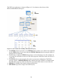
8.2 The Web Part Implementation
The Process Designer has been integrated in SharePoint as a Web Part according to the Web
Part integration chapter seen earlier. In this chapter a couple of different approaches are
shown how to use the InitParams and thereby showing the approach that is used by the
Process Designer.
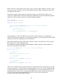
8.2.1 Passing data to Silverlight
In the chapter Integrating Silverlight in SharePoint the InitParams are described as a method
to communicate with the Silverlight plug-in at startup from the SharePoint Web Part. Below is
a piece of code from the Process Designer tool. Instead of passing a string with comma
separated key/value pairs it uses XLinq to create an XML string.
Collection<XElement> siteUserGroupElements = new Collection<XElement>();
foreach (SPGroup group in SPContext.Current.Web.Groups)
{
XElement item = new XElement("SiteUserGroup",
new XElement("Name", group.Name));
siteUserGroupElements.Add(item);
}
Collection<XElement> elements = new Collection<XElement>();
XElement siteUserGroups = new XElement("SiteUserGroups",
siteUserGroupElements);
elements.Add(siteUserGroups);
XDocument document = new XDocument(new XElement("Root", elements));
XLinq is a lightweight XML programming API and is a member of the LINQ Project family.
XLinq is an in-memory API designed to take advantage of the latest .NET Framework
language innovations.
The XDocument object that is created on the last line of code above is then converted to a
string and passed the InitParams. Converting the object to a string is done with the code
shown below.
StringBuilder stringBuilder = new StringBuilder();
XmlWriterSettings xmlWriteSettings = new XmlWriterSettings();
using (XmlWriter xmlWriter = XmlWriter.Create(stringBuilder,
xmlWriteSettings))
{
document.Save(xmlWriter);
}
string xmlString = stringBuilder.ToString();
8.2.2 Passing data with an XML Data Island
Instead of passing an XML string directly with the InitParams method of the Silverlight
control a LiteralControl can be used, within this control an XML Data Island is created. The
id of the Data Island is then passed as a parameter to the Silverlight plug-in via the InitParams
30
property. The LiteralControl is added the same way as the Silverlight control is added to the
HTML page.
Controls.Add(silverlightControl);
string xmlDataIsland = "<XML id='INIT_DATA'>{0}</XML>";
LiteralControl literalXMLIsland = new LiteralControl
(string.Format(xmlDataIsland, xmlString));
Controls.Add(literalXMLIsland);
The XML Data Island can be picked up by the Silverlight application by using the id that is
passed with the control. By working with the HtmlPage class Silverlight can access the
HTML DOM. Once the HtmlElement of the XML Data Island is found the XML can be
extracted, this is done by using the GetProperty method asking for the value of the
innerHTML as shown in the code sample below. [19]
public Page(string controlid)
{
InitializeComponent();
string xmlstring = string.Empty;
if (controlid != null)
{
HtmlElement ctl = HtmlPage.Document.GetElementById(controlid);
if (ctl != null)
xmlstring = (string)ctl.GetProperty("innerHTML");
}
}
8.2.3 The Silverlight Control
The Silverlight control is created in the overridden CreateChildControls method of the Web
Part base class. Here information is set concerning where the Silverlight application can find
the XAP file which is loaded and executed by the Silverlight plug-in in the browser. The size
of the control is set using the Width and Height property and the appropriate parameters are
passed to the InitParameters property.
protected override void CreateChildControls()
{
ctrl = new Silverlight();
ctrl.ID = "SilverlightNavigation";
ctrl.Source = "/_layouts/NavigationWebPart/SilverlightNavigation.xap";
ctrl.Width = new System.Web.UI.WebControls.Unit(876);
ctrl.Height = new System.Web.UI.WebControls.Unit(631);
ctrl.InitParameters = "initXml=" + CreateXMLString();
Controls.Add(ctrl);
}
The XAP file is placed in the _layouts folder and not in a SharePoint document library. This
is to make Silverlight application available in any site collection that is hosted on the
SharePoint server. Having it in the _layouts folder is a good location for making it globally
accessible.
8.3 Drag-and-Drop
Silverlight support a number of mouse related events. All these events can be handled by any
element inheriting from the UIElement class. Click-handling events for the mouse are very
31
similar to key-board events. Click related mouse events associated with the mouse are;
MouseLeftButtonDown and MouseLeftButtonUp which are self explanatory. When the left
mouse button is selected its corresponding event handlers receive a MouseButtonEventArgs
object. It inherits from the MouseEventArgs class which gives information concerning the
mouse when the event was triggered. By calling the GetPosition method the location of the
cursor in relation to a specific UIElement is received. In addition Silverlight supports mouse
movement related event handlers. These are the MouseEnter, the MouseMove and
MouseLeave events, which are triggered when the mouse enters, moves within and leaves a
UIElement. These events are also passed a MouseEventArgs parameter so that the position of
the element can be captured.
When implementing the drag-and-drop feature the first step to be taken is to listen to the
MouseLeftButtonDown event.
processCanvas.MouseLeftButtonDown += new
MouseButtonEventHandler(processCanvas_MouseLeftButtonDown);
By doing this the original position of the mouse can be captured as well as the fact that the
mouse is depressed. To correctly respond to mouse events, ownership over the mouse has to
be claimed. By calling the CaptureMouse method of the UIElement this is accomplished.
private void processCanvas_MouseLeftButtonDown(object sender,
MouseButtonEventArgs e)
{
ProcessCanvas processCanvas = sender as ProcessCanvas;
this.processCanvas = processCanvas;
startingDragPointImage = e.GetPosition(processCanvas);
processCanvas.CaptureMouse();
processCanvas.MouseMove += new
MouseEventHandler(processCanvas_MouseMove);
processCanvas.MouseLeftButtonUp += new
MouseButtonEventHandler(processCanvas_MouseLeftButtonUp);
}
With this information the objects position can be programmatically changed using the
MouseMove event which updates the position using the GetPosition method.
private void processCanvas_MouseMove(object sender, MouseEventArgs e)
{
ProcessCanvas processCanvas = sender as ProcessCanvas;
MainCanvas mainCanvas = processCanvas.Parent as MainCanvas;
Point CanvasPoint = e.GetPosition(mainCanvas);
Double xPoint = CanvasPoint.X - startingDragPointImage.X;
Double yPoint = CanvasPoint.Y - startingDragPointImage.Y;
if (xPoint >= 0 && (xPoint <= (mainCanvas.ActualWidth –
processCanvas.Width)))
Canvas.SetLeft(processCanvas, xPoint);
if (yPoint >= 0 && (yPoint <= (mainCanvas.ActualHeight processCanvas.Height)))
Canvas.SetTop(processCanvas, yPoint);
}
32
Dropping the object is done with the MouseLeftButtonUp event which restores the mouserelated events. [12]
private void processCanvas_MouseLeftButtonUp(object sender,
MouseButtonEventArgs e)
{
ProcessCanvas processCanvas = sender as ProcessCanvas;
processCanvas.ReleaseMouseCapture();
processCanvas.MouseMove -= new
MouseEventHandler(processCanvas_MouseMove);
processCanvas.MouseLeftButtonUp -= new
MouseButtonEventHandler(processCanvas_MouseLeftButtonUp);
}
8.4 Data Binding
Connecting a data source to a user interface element such as a text block can be done in a oneway or a two way fashion. One way is simply to display data in the UI and two way is to
reflect the user interaction in the underlying data source. In general the data sources in
Silverlight are objects or collections of objects with belonging properties that can be accessed.
The Binding markup extension can be accessed both from the code-behind and the XAML
markup. The extension cannot be set directly a binding class has to be used. The
VersionHistoryListBoxItem class below is used for this purpose when binding data to the
version history list box.
public class VersionHistoryListBoxItem
{
public string Description { get; set; }
public string Name { get; set; }
}
The list box items consist of two text blocks, for binding each of the properties of the class.
When wanting to bind the Description property in one of the TextBlocks the first step is to use
the Binding extension in the XAML markup to the Text property.
<TextBlock x:Name="Description" Text="{Binding Description}"/>
The second step is to set the DataContext property to the VersionHistoryListBoxItem object.
The Binding markup provides three modes OneTime, OneWay and TwoWay. These modes
control how the data is bound and how the data flow between the user interface and the data
source.
• OneTime: The binding is done once. Any changes will not be seen in the UI.
• OneWay: The data flows from the data source to the user interface. When the data
source changes the UI is updated.
• TwoWay: The data flows in both directions. Any changes in the UI are reflected in the
data source and the other way around.
Below is a listing of valid syntax for the Binding Markup Extension. [12]
•
{Binding}
Most commonly used with item templates. The mode of operation
is one way.
33
•
•
•
{Binding path}
Specifies what property that supplies the data. Separating the
properties with a dot for going deeper in the class hierarchy.
{Binding properties} Provides the ability to set data binding configuration properties
using name=value syntax.
{Binding path, properties} A combination of the previous two allowing specifying which
object property supplies the data and configuring it.
8.5 Using Styles
Styling in Silverlight is similar to how CSS properties work. User interface elements can
reuse fonts, colors and sizes specified as styles to a FrameworkElement. When developing
larger applications styles are good for grouping properties and specific values that can be
reused. Properties that are grouped into styles are from different Silverlight controls. For
example are the FontSize, Foreground, Margin and TextWrapping good properties to put into
a style for TextBlocks.
When specifying a style it must be given a name as well as the target type where it will be
applied. The target type is the name of the class that will use the style. The name has to match
directly, it will not automatically apply to descendents of a specified class, making UI styling
predictable. Because styling can be applied to all the relevant controls they are placed in the
application resource dictionary in the App.xaml file.
<Application xmlns="http://schemas.microsoft.com/winfx/2006
/xaml/presentation"
xmlns:x="http://schemas.microsoft.com/winfx/2006/xaml"
x:Class="SilverlightNavigation.App"
xmlns:vsm="clr-namespace:System.Windows;assembly=
System.Windows"
xmlns:d="http://schemas.microsoft.com/expression/blend/2008"
xmlns:mc="http://schemas.openxmlformats.org/
markup-compatibility/2006"
mc:Ignorable="d"
xmlns:controls="clr-namespace:Microsoft.Windows.Controls;
assembly=Microsoft.Windows.Controls"
>
<Application.Resources>
<Style x:Key="ContentDescription" TargetType="TextBlock">
<Setter Property="FontSize" Value="12"/>
<Setter Property="TextWrapping" Value="Wrap"/>
</Style>
</Application.Resources>
</Application>
Each style has an x: Key that is the key of the resource which is applied to the user interface
element. When applying the style the StaticResource markup extension is used for the Style
attribute.
<TextBlock Style="{StaticResource ContentDescription}"/>
A drawback with the styles in Silverlight is the lack of conditional styling and style
inheritance which is supported in WPF. Conditional styles are useful for applying styles to
framework elements depending on certain conditions, for example hovering over an element.
The second drawback is style inheritance. A new style can be defined with a combination of
new setters and inheriting setters from its parent.
34
8.6 Using Control Templates
Templates are for Control-based classes and are used for changing how the controls are
rendered visually. This is possible because there is a separation in how they look and what
they do.
Each control can have different states, such as disabled. A control template lets the developer
define what the control looks like in each of its states. It is a kind of changing the look and
feel of the control because the visual appearance changes when the user interacts with it.
Every Control in Silverlight has a property Template which is located in the Control class. By
setting this property the developer is resetting the controls appearance. From this reset state
the look and feel can be adapted as wished. The new appearance that is defined in the below
code sample is a round close button.
<Style x:Key="CloseButton" TargetType="Button">
<Setter Property="HorizontalAlignment" Value="Right"/>
<Setter Property="Width" Value="15"/>
<Setter Property="Height" Value="15"/>
<Setter Property="Template">
<Setter.Value>
<ControlTemplate>
<Border x:Name="brd1" Width="14" Height="14" CornerRadius="15">
<Border.Background>
<RadialGradientBrush GradientOrigin=".3, .3">
<GradientStop Color="#FFF" Offset=".15"/>
<GradientStop Color="#777" Offset="1"/>
</RadialGradientBrush>
</Border.Background>
<TextBlock x:Name="txt1" Foreground="#222" TextAlignment="center"
Text="r" FontSize="9" VerticalAlignment="center"
FontFamily="Webdings"/>
</Border>
</ControlTemplate>
</Setter.Value>
</Setter>
</Style>
The button above is forced to display the letter r as a Webdings font, which is a
representing close. If the button was to be used as a general purpose button control
template it wouldn’t be a very useful, because a new control template would have to be
defined for each text that the button presents. This issue is solved by using the
TemplateBinding markup extension. When using the TemplateBinding markup extension for
a button a special class called the ContentPresenter has to be used. This class makes it
possible to display all kind of content that is possible for a button but also other controls
Content property. By changing the TextBlock tag above by the one below this is
accomplished.
<ContentPresenter HorizontalAlignment="Center" VerticalAlignment="Center"
Content="{TemplateBinding Content}" />
The button control template above does not give the user any visual feedback reflecting the
different visual states a Button control can have. By using something called the Visual State
Manager defining the different states is possible. Each control has a set of visual state groups
and visual states defined to them. The states within the group are mutually exclusive but the
35
control can be in several states at the same time from the visual groups that is defined for it.
The Figure 8.6-1 shows two state groups and the visual states that are valid within them.
Figure 8.6-1 Visual State Groups and Visual States [21]
When creating a control that supports the visual states and groups that are shown above these
have to be defined on the Button class using attributes. The control can then specify how it
should act in each state; this can be very troublesome when doing it in code. By using
Microsoft Expression Blend defining control templates and their states makes the life of the
developer much easier. [21]
36
9 WCF and Silverlight
The most effective way to communicate with server-side code is using a web service. The
basic concept is to include a web service with an ASP.NET web site and let the Silverlight
application call its methods. The web service will then perform any server-side tasks that are
necessary.
9.1 Creating a Silverlight enabled Service
Creating a WCF service in Visual Studio is pretty straight forward. This is accomplished by
right clicking on the ASP.NET web site and under the Add New Item options choose
”Silverlight-enabled WCF Service”. This will create a service endpoint file with the extension
.svc. This file only contains one line of code that tells ASP.NET where to find the web service
code. This will also create a corresponding .cs file where the implementation of the service
interface is placed.
9.2 Consuming the Web Service
Consuming a web service in Silverlight is much like consuming the service in any other .NET
application. The first thing that has to be done is to create a proxy class by adding a Visual
Studio web reference. By choosing Add Service Reference on the Silverlight project and
adding the URL to the .svc file of the web service and clicking OK this will be accomplished.
This generates a proxy class that the Silverlight application uses to call the web service
methods.
9.3 Calling the Web Service
All web service calls in Silverlight are asynchronous; this means that a service call will not
wait for an immediate response from the server. Instead the call is done and other code can
run in the mean time. When the server is finished executing its part of the code it sends a
response which the proxy class takes care of by triggering the corresponding proxy event,
which has the form MethodNameCompleted, this is where the result has to be processed.
The sample code below is taken from the Process Designer tool for loading the process model
at the startup of the application. This is a typical way for calling the web service. First an
instance of the proxy class is created. An event handler is attached to handle the completed
event. The web service call is then done with the form MethodNameAsync. And finally the
service is closed with the CloseAsync method.
ProcessNavigationClient proxy = new ProcessNavigationClient();
proxy.GetMainCanvasesCompleted += new EventHandler
<GetMainCanvasesCompletedEventArgs>(proxy_GetMainCanvasesCompleted);
proxy.GetMainCanvasesAsync();
proxy.CloseAsync();
To handle the result of the call the completed event and the corresponding EventArgs object
has to be handled. The proxy class will generate different EventArgs objects for each method.
The Result property is then typed to match the response data type. [11]
9.4 WCF and the SharePoint Object Model
To use the SharePoint object model within the web service the Microsoft.SharePoint
namespace has to be added as a reference. By default WCF works outside ASP.NET and
37
because of that also outside SharePoint. The scope of WCF is much larger than just ASP.NET
therefore this is reasonable. To get the current site collection the static SPContext object is
used. To enable the web service to get a reference to SPContext the service has to be told to
run within the ASP.NET context. This is done by adding the following line to the web.config
file of the web service.
<system.serviceModel>
<serviceHostingEnvironment aspNetCompatibilityEnabled="true" />
...
</system.serviceModel>
The sample code below is taken from the Process Designer tool. The call is made at the
application startup to load the process model that has been saved in a Document Library. The
using statements are used when the developer wants to have supervision of when the resource
allocated within it should be released. This is good when handling with limited resources such
as file handles and network connections. The release of memory is otherwise done by the
common language runtime, which does this in a non-deterministic manner. Using the
approach below it is possible to drill down in SharePoint object model, and in this case ending
up with the SPDocumentLibrary object where the files for loading the process model is
located.
[OperationContract]
public Collection<MainCanvasProp> GetMainCanvases()
{
Collection<MainCanvasProp> props = new Collection<MainCanvasProp>();
using (SPSite site = new SPSite(SPContext.Current.Site.ID))
{
using (SPWeb web = site.OpenWeb())
{
SPDocumentLibrary library =
(SPDocumentLibrary)web.Lists["Process Hierarchy"];
if (library != null)
{
...
}
return props;
}
}
}
9.4.1 The XmlSerializer
The XmlSerializer lets the developer serialize and deserialize objects which provides a
higher-level alternative to just reading and writing individual pieces of data. The
XmlSerializer converts objects into a stream of bytes which can be pushed to any stream. It
can also do the reverse by reading a stream of bytes and convert into an object. To be able to
use this feature the System.Xml.Serialization.dll has to be referenced within the project. The
XmlSerializer works with every class but have a couple of requirements:
•
•
The class that wants to be serialized has to have a constructor with no arguments. This
class is used when the XmlSerializer is deserializing the byte stream.
The class has to be built up by public settable properties. By using reflection the
XmlSerializer will read them for serializing an object and set them also using
reflection when deserializing. Private data is ignored as well as any validation.[23]
38
The code sample below is taken from the CheckIn WCF service method which is called when
checking in a process level of the Process Designer tool. It demonstrates how to serialize an
object into a stream which can be saved to SharePoint document library. The prop object is of
type MainCanvasProp class which holds the information concerning a process level.
Stream documentStream = new MemoryStream();
StreamWriter writer = new StreamWriter(documentStream);
XmlSerializer s = new XmlSerializer(prop.GetType());
s.Serialize(writer, prop);
writer.Flush();
The code sample below is taken from the WCF service method which is called when loading
the process model. The file instance which is a SharePoint SPFile object is read into a Stream
object as binary stream. An instance of the XmlSerializer is then created which is customized
to use the MainCanvasProp class. By applying the Deserialize method the stream is converted
into a MainCanvasProp object.
Stream stream = file.OpenBinaryStream();
StreamReader reader = new StreamReader(stream);
XmlSerializer s = new XmlSerializer(typeof(MainCanvasProp));
MainCanvasProp prop;
prop = (MainCanvasProp)s.Deserialize(reader);
reader.Close();
9.5 Error Handling
WCF has the ability to throw exceptions on a service call. The unfortunate thing is that
Silverlight does not support it. Any exception that is thrown will be translated by the browser
into a 404 File Not Found error. There are a couple of workarounds that can be used to
overcome this issue. One workaround is using an extra Error property to the data that is
returned to the Silverlight application. This solution is not optimal though. It makes the
simple return value more complicated and it mixes good and bad data in the same object and
will therefore break the single responsibility rule. A better solution is to use the ability to
define a WCF service signature using the OUT parameter which can be accessed through the
EventArgs on the event handler for completing the call. [12]
WCF
[OperationContract]
SomeObject GetSomeData(String someId, out MyErrorObject myError);
Silverlight
private void proxy_GetSomeDataCompleted(object sender,
GetSomeDataCompletedEventArgs e)
{
if (e.Error != null)
{...}
if (e.myError != null)
{...}
else
{...}
}
9.6 Other Communication Patterns
The difference between a Silverlight Web Part and a normal SharePoint Web Part is that the
Silverlight Web Part is executed in the browser and not on the Server. Therefore the
39
Silverlight application will not have access to the SharePoint object model. The goal is
therefore to be able establish some kind of communication between the UI of Silverlight and
the SharePoint server-side to access objects and data.
The Process Designer tool uses one approach defining a server-side web service which
accesses the SharePoint object model. This web service is then consumed and called from the
Silverlight application. There are other patterns that can be taken into account. Here is a list of
thinkable patterns.
•
•
•
Using the Silverlight WebClient object to communicate with the SharePoint built-in
Web service.
Create a client-side adapter that is embedded in the Web Part. The Silverlight
application can then communicate with the adapter through the browser. The adapter
will then make AJAX-style calls to a built in SharePoint Web service.
The last thinkable solution is to use the above approach. But instead of communicating
with the built in SharePoint Web services it talks to a self implemented service. Figure
9.6-1 shows this approach. [23]
Figure 9.6-1 Communication pattern [23]
40
10 The Model-View-ViewModel Pattern
The Model-View-Control pattern is well known and commonly used when developing
ASP.NET applications with a request/response style. The M-V-VM (Model-ViewViewModel) pattern has not been discussed as much as a formal pattern. However, it works
well for client applications that use interactive or dynamic user interfaces that are data-bound.
This is the case when coming to Silverlight.
The pattern consists of three parts the Model/DataModel, View and the ViewModel.
•
•
•
Model/DataModel. This part represents the data that the application is operating over
as well as the data access mechanism. Analogous to the Model in the MVC pattern.
View. The View is the user interface that displays the data and enables user
interaction. It is typically in a declarative language like XAML or HTML.
ViewModel. Also read as “The View’s Model” this part is responsible to represent the
data in a more suitable way for the view. It also has operations that are performing
work and that often change the data that the view is bound to.
The code-behind pattern that is the natural approach to use when programming Silverlight
applications uses a similar approach. Having UI components that are associated with codebehind that loads data and implementing logic for user input and interaction with eventhandlers. Figure 10-1 represents this pattern. A problem with the pattern is that it mixes
application logic with the visual presentation. This leads to an application that is harder to
test. It also effects the separation of the designers work and the work of the developer.
Figure 10-1 The code-behind pattern [25]
The M-V-VM pattern tries to separate the logic from the presentation. The data that is
displayed are implemented as properties of the ViewModel that the View gets via databinding. Further on, the ViewModel also have methods that have logic that is consumed by
the View using commanding. The key is that the ViewModel is independent from what
controls that build up the View. Figure 10-2 illustrates this pattern. [25]
41
Figure 10-2 The Model-View-ViewModel pattern [25]
11 Silverlight Testing and Debugging
Before integrating the Silverlight application in the SharePoint Web Part it is recommended
that it works as much as possible. This is most easily done in the Web Application project that
is created in Visual Studio when developing the Silverlight application. When the application
is working within this environment it should be wrapped in a Web Part. Once it is wrapped in
the Web Part no breaking points can be set for debugging in the Silverlight application.
When troubleshooting problems with the Silverlight application it is good to use a HTTP
debugger. Especially when the application uses Web Service calls. When developing the
Process Designer tool the web debugging program fiddler2 was used. It gives a clear view of
what data is sent to and from the web browser and the server where the Web Service is
located and what calls fails. It also tells if a cross domain file is being requested.
When the XAP file is downloaded from the server it is cached in the browser. When new
versions of the XAP file is available for download from the server the browser will still use
the cached file. It is therefore necessary to clear the browser cache before testing newer
versions. [24]
11.1 Unit testing
Testing is an important part of the development life-cycle of software. Software patterns like
dependency injection and M-V-VM makes it easier to design code that is easier to test. There
is no Silverlight testing framework that is integrated with Silverlight itself. The Silverlight
testing framework is available with the release of the Silverlight control source. [26]
A rather common misperception is that every test written using a test framework is a unit test,
but there are a number of different tests that can be written to test code. A test can be seen as
not being unit test if:
•
•
•
•
•
It communicates with the database
It communicates across the network
It interacts with the file system
It can run at the same time as other unit tests
The environment has to be re-configured to run them
42
Tests that do the things listed above can easily be written using a testing framework. But it is
important to separate them from the real unit tests that can be run whenever and in a fast
manner. [27]
It is of essence to be able to write unit test code that is easily decoupled from code that makes
cross boundary calls. Instead of making a test that interacts with a database the data has to be
collected in some other mean by for instance using dependency injection or mocks.
A good practice when writing tests to a Silverlight application is to separate them into three
separate categories.
•
•
•
Unit Test. Tests a single unit, normally a method in a single class. It should not do
any cross boundary calls, should run fast without any side effects.
Integration Test. This is testing how multiple classes integrate with each-other or
how the class integrates with the environment. I.e. accessing data over a web service
or accessing the data base.
Smoke Test. This is for testing how the user is interacting with the application. This
leads to cross boundary calls, file system access etc. These tests are usually automated
by the user interface.
There are other kind of tests that can be done as well, like performance- , acceptance-, and
stress- tests. These are often written in other testing frameworks.
It is good to keep the unit tests, integration tests and the smoking tests separate. Having the
unit tests running as fast as possible which is easier to accomplish when they do not make
cross boundary calls. If tests become slow developers tend to not be running them. A good
way of keeping them separate is to create different projects for each test. In the Silverlight
testing framework the separation can be done using tags to test classes and test methods. [26]
11.2 The Silverlight testing framework
The unit test framework for Silverlight was first released in conjunction with the release of the
source code to the Silverlight controls. It runs in the web-browser both on PCs and Macs. The
Microsoft.Silverlight.Testing framework is easy to use and lets the developer create crossplatform, cross-browser tests.
Using unit tests are useful, the more tests the more confident the developer can be that the
code is running correct. The test projects are packaged like any other Silverlight application
so no additional installation is needed to be able to run the tests.
11.2.1 Creating a simple test
The easiest way to start using the unit test framework for Silverlight is to use the two Visual
Studio templates that have been created for the Silverlight testing framework. The first
template is for adding a Silverlight test application to a Visual Studio solution and the second
template is an item template that adds a test class to the test project.
In addition two assemblies are needed which comes with the source code of the Silverlight
controls. These are the Microsoft.VisualStudio.TestTools.UnitTesting.Silverlight.dll and the
Microsoft.Silverlight.Testing.dll.
43
The metadata and assertion types are found in the
Microsoft.VisualStudio.TestTools.UnitTesting namespace. And the tests are made up of test
classes and test methods. The code for a simple test class containing one test method can be
seen below.
using System;
using Microsoft.VisualStudio.TestTools.UnitTesting;
namespace CIT.UnitTest.ProcessDesigner
{
[TestClass]
public class Test
{
[TestMethod]
public void PassTest()
{
Assert.IsTrue(true);
}
}
}
When the test is run a web-browser is shown. This test is without any Silverlight control or
interface therefore nothing will be shown on the plug-in surface to the left. The only thing that
is shown is the log which is seen in Figure 11.2.1-1. The log consists of the test classes and
the test methods that run. Showing any classes or methods that fail and how many tests that
ran.
Figure 11.2.1-1 Running unit tests
11.2.2 Creating UI tests
Using the Silverlight testing framework makes it is possible to simulate user activity by
calling methods that triggers application logic. There is a large set of functionality that can be
tested within the Process Designer project.
To be able to test the Process Designer Tool which is located in a separate Silverlight project
a reference has to be added to Process Designer project in the test project. In addition any
resources that are defined in the App.xaml file have to be placed in the individual .xaml files
44
where they are used. This is because the resources will not be available to the test project
being in a separate app file. Moving the resources is easily done with Expression Blend by
using the Resource tab in the upper right corner.
Since the Silverlight test framework is just another Silverlight application there is no
possibility to do any UI automation tests, like user initiated mouse clicks and key presses.
What can be tested is the code that is connected to for instance button events, that the visual
tree is updated, and that the data source is correctly updated on invocation.
To be able to create more advanced Silverlight specific tests the SilverlightTest base class can
be inherited which is located in the Microsoft.Silverlight.Testing namespace. This class has
support for interacting with the root visual and the HTML DOM bridge. In addition the class
has a number of helper methods that can be used with the [Asynchronous] attribute, which
enables writing tests beyond the scope of the test method until the TestComplete method is
called.
To be able to do UI tests on the Process Designer tool, the InternalsVisibleTo attribute has to
be used which allows the test assembly to view internal types and methods. This is done by
adding the line below to the AssemblyInfo.cs file in the Process Designer project.
[assembly: InternalsVisibleTo("CIT.UnitTest.ProcessDesigner")]
This lets the test project assembly call methods within the Process Designer project having the
keyword internal.
To make the testing scenarios easier a TestInitialize method will be called before the
TestMethod. In this method a new instance of the Page is created and added to the TestPanel.
If the TestPanel is accessed in a test the content will be cleared before the next test is run.
This saves time when writing tests, not having to do any manual cleanup of temporary visuals
that are used within the test. Below a sample code is shown which instantiates a Page with the
parameter null. By doing this a “mock” process model is loaded for testing purposes.
[TestClass]
public class Test : SilverlightTest
{
private Page page;
[TestInitialize]
public void PreparePage()
{
page = new Page(null);
TestPanel.Children.Add(page);
}
}
The test example below will use the instance of the Page to test the logic when a user clicks a
process image which triggers displaying the name of the process in the bottom left corner of
the process design surface.
45
[TestMethod]
public void ClickedProcessTextTest()
{
MainCanvas mainCanvas; ProcessCanvas processCanvas = null;
page.mainCanvasDictionary.TryGetValue(0, out mainCanvas);
foreach (UIElement element in mainCanvas.Children)
{
processCanvas = element as ProcessCanvas; break;
}
mainCanvas.Prop.IsCheckedOut = false;
ClickOnProcessImage(processCanvas);
Assert.AreEqual(page.ClickedProcessTextBoxMain.Text, "Selected: TEST");
}
private void ClickOnProcessImage(ProcessCanvas process)
{
page.processCanvas_MouseLeftButtonDown(process, null);
}
The mainCanvasDictionary holds all information concerning the process model. The
mainCanvas with id 0 is the first level of the process model. By iterating over its children
(foreach (UIElement element in mainCanvas.Children)) each process image can be
reached which is within a ProcessCanvas object. The helper method ClickOnProcessImage
invokes the method which is triggered when a user clicks on a process image. The last row
performs the actual test. The first process is “mocked” to have the value “TEST”. By
comparing the value of the object which displays the text and the expected string the test is
completed. The application interface is added to the TestPanel before each test is run and
removed when the test is finished. Because the tests run very fast, it is possible to run
thousand of tests with this browser experience. Below is what the test would look like if the
screen froze in the middle of the test. The “Selected: TEST” text is seen on the process design
area which is triggered by the test. [28]
Figure 11.2.2-1 The ClickedProcessTextTest test
46
12 Result
The Silverlight tool developed in conjunction to this thesis report meets the purpose of thesis
well. Using Silverlight to develop more user friendly and interactive applications within
SharePoint is a good way to meet customers ever increasing demands of having intuitive and
user rich applications.
The Process Designer tool has an appealing graphical user interface where processes can be
dragged around a designer surface where they can be edited. Metadata and links to documents
within SharePoint can be added to each process level. The tool interacts closely with
SharePoint functionality by using a document library where the built in feature for checking
in and out of processes is used as well as being able to keep a history of the evolution of
processes as they are developed over time.
To create a similar tool in an HTML environment of a browser is possible. This would include
using scripting languages integrated with the HTML for creating interactivity with the
SharePoint object model on the server. Using this approach would make development both
time consuming and more complicated. Silverlight makes it easier by using a subset version
of the .NET Common Language Runtime, allowing the programmer to use C# when
developing client side applications in exactly the same fashion as developing desktop
applications. Being able to work within one environment using object oriented code makes it
not only easier but also more robust and reliable.
The Process Designer tool uses a number of built in controls for presenting information
attached to processes and process levels. The controls are delivered with the Silverlight SDK,
having a standard Windows like set of animations and styles. The tool uses its own control
templates to the controls resulting in a similar look and feel over the entire application. This
increases the familiarity to the application from a user perspective.
A major point of the thesis has been the actual integration of the tool and how well it works
within the SharePoint site. The integration is accomplished by a set of predefined steps. By
following these steps the integration does not cause any major trouble. The Process Designer
tool has been integrated as a Web Part, which is added from the Web Part gallery within
SharePoint. This makes it possible to add the application at any location within the SharePoint
site collection. The Visual Studio Extension template for WSS 3.0 makes development of the
Web Part which hosts the ASP.NET server-side Silverlight control much easier. The solution
can be deployed to the server from Visual Studio instead of creating installation scripts
manually. Another integration issue is the placement of the Silverlight XAP file. The Process
Designer tool uses the layouts folder, this makes the XAP file available over the entire web
farm, making it possible to use the application on several site collections. When newer
versions are available of the program-code the XAP file can easily be replaced.
Client-server interaction has been accomplished using Windows Communication Foundation.
The service implementation uses the SharePoint object model for interacting with SharePoint
specific objects like document libraries and user group information. Here most of the
integration problems have occurred.
To be able to use the SharePoint SPContext object to get hold of the current site collection
where the service is placed the aspNetCompatibilityEnabled flag has to be set to true in the
configuration of the service. Otherwise the object will return null.
47
A proxy has to be generated by the application when the WCF services are used within the
Silverlight application. This is accomplished by the “Add Service Reference” feature in
Visual Studio. This will generate proxy code for doing asynchronous calls from Silverlight.
This feature has caused trouble in combination with deploying the service in IIS, giving
cryptic error messages. To overcome it a clean development environment has been used
where the solution has been added. Reference 15 in the reference list gives an interesting
approach using WCF in Silverlight without the proxy generation feature.
A general problem with the integration has been the possibility to debug code. Once the
Silverlight application is compressed in a XAP file and uploaded to the server it cannot be
debugged when executed in the browser within the SharePoint site. This is especially
troublesome if the WCF service call fails. By using a web debugging tool like fiddler the
service calls and their responses can be monitored. This helps locating the problem but if the
problem is within the Silverlight code it can still not be debugged.
48
13 Discussion
Silverlight being a rather new technology on the market has a number of limitations, but more
features are added as new versions are released. When being forced to use workarounds to
accomplish features that are not yet supported is never good. The Process Designer tool uses a
WCF service. At this point exceptions are not supported within Silverlight that are thrown
from the service. As a result an extra operation contract has to be specified where the error
can be saved which can then be read in the Silverlight application.
All communication from within Silverlight is done asynchronously. This includes making
WCF service calls. An event handler is created to handle the response when the call returns.
Because the Process Designer needs the response of the service calls to keep on working
within the application a blocking element in the form of a process bar is used. It is important
to keep in mind when developing applications that run in a browser environment to keep the
communication to the server side as limited as possible making server calls only when they
are absolutely necessary. Otherwise the application will become unresponsive and slow.
Keeping the amount of data that is sent between the client and the server at a minimum also
helps making the calls quicker and therefore also more responsive.
The current version of the Process Designer tool has got some limitations. Currently it is only
possible to use one instance of the application within a SharePoint site collection. This is due
to the fact that it only uses one static document library for storing the process model.
Specifying process names is limited to one line and there are a predefined set of colors and
fonts that can be applied to the text of the process name. These colors and fonts are available
within the Silverlight framework. There is also no possibility to skew the text within the
process for making it fit better all kind of process image designs.
49
14 Conclusion
There are some important aspects when developing Silverlight applications and additionally
some very useful things to keep in mind when the integration is made within SharePoint.
All web service calls in Silverlight are done asynchronously. This architectural decision
increases complexity but prevents the application from hanging. Silverlight supports both old
ASMX Web Services and the newer WCF standard. Many of the out-of-the-box ASMX Web
Services offered by SharePoint cannot be used by Silverlight. This is because these service
methods return XMLNode sets which is not supported by Silverlight. By using a wrapper
Web Service the returning type of the Web Service calls can be transformed into something
that is readable within the Silverlight application.
The Silverlight project within Visual Studio creates a test.html page that enables the
programmer to test the application during development. If the application consumes a Web
Service there is no possibility to test the application within Visual Studio. This is because the
Silverlight application is running as a local web application and this is a different domain as
the web service. The Process Designer tool overcomes this by using a debugging flag that
tells the application to load static test data that is defined within the program instead of
making the Web Service method.
The most important thing to keep in mind when developing Silverlight applications is to
create code that is easy to maintain, refactor and test. The Model-View-ViewModel pattern
presented in the thesis helps the developer to accomplish this. The Silverlight programming
model implies a tight integration between the user interface and the data that it works with.
This makes maintenance, refactoring and testing more difficult. The pattern separates the
application in separate layers, preventing one layer to have intimate knowledge of another
layer.
During development of the Process Designer tool the Model-View-ViewModel pattern has
not been applied this is because the tool has been used for evaluating and learning the
technology of Silverlight. It is recommended when any further development of the Process
Designer is done that the pattern is applied. A few unit tests have been written mainly for
evaluating the Silverlight testing framework. After applying the Model-View-ViewModel
pattern more tests can be written adding assurance that the system works in a correct manner.
A future functionality recommendation to the Process Designer tool is to make it possible to
add more instances of it within a SharePoint site collection. This could be done by being able
to configure the name of the image library and the document library it uses when the
application is added for the first time on the site. These configuration settings could be stored
in a document library on the top level site. Further on a skewing functionality could be added
to the Process image title. Skewing is supported by Silverlight and the extra parameter it
causes can be saved in the document library together with the other properties that are saved.
The last issue that is good to be taken into consideration is the ability to be linked directly
using an URL to the process level of interest.
50
15 References
[1] Microsoft MSDN, Windows SharePoint Services 3.0, http://msdn.microsoft.com/svse/library/bb931737(en-us).aspx, 2009
[2] Pattison, Larson, Inside Microsoft Windows SharePoint Services 3.0, Microsoft Press,
Redmond, 2007
[3] Pattison, Discover Significant Developer Improvements in SharePoint Services,
http://msdn.microsoft.com/sv-se/magazine/cc163578(en-us).aspx, July 2006
[4] Pattison, Masterman, Use Windows SharePoint Services as a Platform for Building
Collaborative Applications, http://msdn.microsoft.com/sv-se/magazine/cc163948(en-us).aspx,
July 2004
[5] Dufresne, Martin, Process Modeling for E-Business,
http://mason.gmu.edu/~tdufresn/paper.doc, March 2003
[6] Burlton, Business Process Management: Profiting Process, Sams Publishing, United
States, 2001
[7] Smith, Fingar, Business Process Management: The Third Wave, MK Press, United States,
2003
[8] Masterman, Pattison, Use Windows SharePoint Services as a Platform for Building
Collaborative Apps, Part 2, http://msdn.microsoft.com/sv-se/magazine/cc188713(en-us).aspx,
August 2004
[9] Jamison, Cardarelli, Hanley, Essential SharePoint 2007, Addison-Wesley, New York,
June 2007
[10] MacDonald, Silverlight 2 Visual Essentials, Appress L. P, United States, 2008
[11] MacDonald, Pro Silverlight 2 in C# 2008, Apress L. P, United States, 2008
[12] Campell, Stockton, Silverlight 2 in Action, Manning Publications Co. United States, 2008
[13] Microsoft MSDN, Fundamental Windows Communication Foundation Concepts,
http://msdn.microsoft.com/en-us/library/ms731079.aspx, 2009
[14] Löwy, WCF Essentials, http://en.csharp-online.net/WCF_Essentials, 2007
[15] Betz, Understanding WCF Services in Silverlight 2,
http://www.netfxharmonics.com/2008/11/Understanding-WCF-Services-in-Silverlight2#WCFSilverlightServiceSetup, November 2008
[16] Tisseghem. Silverlight BluePrint Guidence,
http://www.u2u.info/Blogs/Patrick/Download/Silverlight_BluePrint_SharePoint_Guidance.zi
p, August 2008
[17] codeplex, Hello World Source Code Project,
http://sl4sp.codeplex.com/Release/ProjectReleases.aspx?ReleaseId=19961#DownloadId=505
18, November 2008
[18] codeplex, Sample 2 – Media Viewer,
http://sl4sp.codeplex.com/Release/ProjectReleases.aspx?ReleaseId=16420#DownloadId=416
10, August 2008
[19] codeplex, Sample 4 - Custom Navigation,
http://sl4sp.codeplex.com/Release/ProjectReleases.aspx?ReleaseId=16420#DownloadId=416
12, August 2008
[20] codeplex, Slider Control Source Code Project,
http://sl4sp.codeplex.com/Release/ProjectReleases.aspx?ReleaseId=19961#DownloadId=506
76, November 2008
[21] Scanlon, Accelerated Silverlight 2, Appress L. P, United States, 2008
[22] Microsoft MSDN, Server and Site Architecture: Object Model Overview,
http://msdn.microsoft.com/en-us/library/ms473633.aspx, 2009
51
[23] Pae, How We Did It: LearingPoint for SharePoint,
http://blogs.msdn.com/sharepoint/archive/2009/04/01/how-we-did-it-learningpoint-forsharepoint.aspx, April 2009
[24] Williams, Tips for Writing Silverlight Web Parts in SharePoint: Part 1,
http://www.synergyonline.com/blog/blog-moss/Lists/Posts/Post.aspx?ID=32, October 2008
[25] Kothari, ViewModel Pattern in Silverlight using Behaviors,
http://www.nikhilk.net/Silverlight-ViewModel-Pattern.aspx, June 2008
[26] Follesoe, Efficient testing in Silverlight 2 using tags,
http://jonas.follesoe.no/EfficientTestingInSilverlight2UsingTags.aspx, October 2008
[27] Haack, Unit Test Boundaries, http://haacked.com/archive/2008/07/22/unit-testboundaries.aspx, July 2008
[28] Wilcox, Unit Testing with Silverlight 2,
http://www.jeff.wilcox.name/2008/03/silverlight2-unit-testing, March 2008
52
Appendix A. User Manual
Introduction
The Process Designer is developed as a Web Part that can easily be added from the Web Part
gallery in SharePoint. The application makes it possible users with the appropriate user rights
to design and navigate through a hierarchy of processes. This is accomplished be using a list
of process pictures that are loaded from a picture library in SharePoint.
The User Manual is separated in three parts. The first part gives a conceptual overview
concerning user groups and versioning. The second part describes the user experience of the
application from the perspective of using the tool as a process designer. The third and last part
will guide the user when using the tool for navigating the process hierarchy.
The Process Designing tool is separated into four areas as can be seen below. Each of the
areas will be described separately for each of the two user categories.
Figure 1 The Processes Designing tool and its areas
Conceptual Overview
User Group and Owner logic
The Process Designing tool uses SharePoint user groups to divide users into two categories;
designers and viewers. The viewer will only be able to navigate through the process hierarchy
and the designer will have full editing rights.
To each process that is added to the process hierarchy a process owner is defined. The process
owner is a SharePoint user group. All users within the specified group have the right to add,
53
delete or edit processes on the sub-process level of the process. Figure 1 is an example of how
the tool is seen by a designer; he is a member of the “Company Portal Members” group which
is the owner of the “Root” process level.
Versioning and Visibility
The Process Designing tool is built upon a versioning feature that can be added to SharePoint
document libraries. Each document in a library can be checked in either as a minor or a major
version. In conjunction to this functionality each process level of the Process Designer tool
has a version attached to it making it possible to decide when a process level is to be made
public to Viewers. If a process level is a minor version it is not seen by Viewers, only major
versions are. In addition it is possible to blend out
The Designer
Area 1
This area is the toolbar area for interacting with individual processes and the whole process
level.
Check in Button
When finished designing new or editing existing processes, the process level has to be
checked in to save the changes. Pressing the check in button the user is prompted with a
popup window within the application. The process level can be checked in as a major or a
minor version. An optional check in comment can moreover be submitted.
Figure 2 Check in
Check out Button
Before any alterations can be done to a process level it has to be checked out. This is to make
sure that no other user is doing design work on the level and therefore risking overwriting
each other’s work.
Delete Button
By pressing the delete button individual processes on the process level can be deleted. The
user is prompted with a popup window within the application. The new window will list all
sub-processes that will consequently be deleted. If any of the sub-process levels are checkedout the process cannot be deleted, not until the sub-process level has been checked in by the
user having it checked out.
54
Figure 3 Delete
Back Button
The back button is for navigation purposes. Pressing the back button will lead the user back to
the parent process level. Pressing the back button that is integrated by the browser will not
have any effect when navigating within the application. This button will only lead the user to
the previous html page. By doing this any changes that have been made to the process
hierarchy will be lost.
Area 2
This area is the interaction menu for adding new processes and navigating the process
hierarchy.
Designer Tab
This tab will list all the available process figures in a list box that can be added to a process
level. By clicking on a figure the user is prompted with a popup. The popup lets the designer
specify a heading to the process. The user can choose the size, font, style and color of the text.
Two expanders are available; the “Process Owner” expander for specifying the process owner
and the “Visible for Groups” expander for specifying what groups should be able to view the
process. In the list of the “Visible for Groups” expander multiple lines can be selected each
line representing a toggle button. In the list of the “Process Owner” only one item can be
selected. Figure 4 below shows how this is accomplished.
Figure 4 Process Owner and Visible for Groups expanders
55
The user can navigate through the different figures by pressing the up and down arrows of the
list box.
Viewer Tab
In this tab a Tree view is to be seen. The nodes in the tree represent each process that is
available. By selecting a node within the tree its sub-process level is to be seen in Area 4. A
node in the tree can be expanded or collapsed by pressing the arrow in front of the process
name.
Area 3
This area is the properties area where properties to the current process level are to be seen.
Document Links Tab
The document links tab is formed as a list box where all the documents connected to the
current process level in view are listed. Within the properties area three buttons are available
for adding, editing and deleting items within the list. Pressing a link within the list will open a
new browser window where the links content is displayed. When pressing buttons add or edit
a popup window is displayed. Here a description can be filled in for the link and the link
itself. Important to notice is that the link has to have the syntax: http://www.google.com to
work. Not only www.google.com.
Figure 5 Document link
Metadata Tab
The metadata tab is for adding textual information about a process level. The metadata values
are listed in a list box. New items can be added, edited or deleted using the buttons available
in the properties area. When pressing buttons add or edit a popup is prompted where the user
can add a name and a description of the metadata.
Figure 6 MetaData
Version History Tab
The version history tab is for viewing earlier versions of the process level that is currently
displayed. The earliest version is listed on top and the newest version is the last item of the list
box. By selecting an earlier version it is displayed in Area 4. Important to notice is that it is
not possible to navigate to sub-process levels when an earlier version is displayed. Therefore
56
the Viewer tab of the interaction menu will be blended out. When wanting to navigate the
process hierarchy the last version of the version history list box has to be re-selected.
Figure 7 Version History
Area 4
This is the main design area where the figures of the process system are displayed and are
added.
Drag and Drop
Within the design area the process figures can be placed. The figures can be dragged around
this area and placed where is best suited. The text within the process figure representing the
name of the process can also be dragged and placed within the process figure.
Double Click
When double clicking the text of a process it can be edited. The same popup is then shown as
when adding a new process to the design area. See Area 2 –> Designer Tab for popup specific
information.
Double clicking the process figure will show the sub-process level of the process.
Information Text blocks
On each corner of the design area status texts are visible,
• Top right corner: The current version of the process level is displayed. Major versions
are displayed with syntax X.0 and minor versions as X.X where X is representing a
number.
•
Top left corner: The SharePoint user group is displayed that is the owner of the
process level in view.
•
Bottom left corner: The process that has been clicked and therefore is in focus is
displayed.
•
Bottom right corner: The name of the process level is displayed.
The Bottom left text block is also used to display status messages when interacting with the
server. These are displayed in a red color after a server call has been made. The following
status messages are currently available:
"Could not find process in the document library"
"Could not locate the process document library"
"Process was successfully checked out"
"Process was successfully checked in"
“The process has already been checked out by: #userName#"
57
"The process is checked out by: #userName#"
"Process and sub-processes were successfully deleted"
The Viewer
On a process-level where the user does not belong to the owner user group he will be limited
to only being able to view the levels properties and navigate to other levels.
Area 1
This area is the toolbar area for interacting with individual processes and the whole process
level.
Check in Button
Not applicable.
Check out Button
Not applicable.
Delete Button
Not applicable.
Back Button
The back button is for navigation purposes. Pressing the back button will lead the user back to
the parent process level. Pressing the back button that is integrated by the browser will not
have any effect when navigating within the application. This button will only lead the user to
the previous html page. By doing this any changes that have been made to the process
hierarchy will be lost.
Area 2
This area is the interaction menu for adding new processes and navigating the process
hierarchy.
Designer Tab
Not applicable.
Viewer Tab
In this tab a Tree view is to be seen. The nodes in the tree represent each process that is
available. By selecting a node within the tree its sub-process level is to be seen in Area 4. A
node in the tree can be expanded or collapsed by pressing the arrow in front of the process
name.
Area 3
This area is the properties area where properties to the current process level are to be seen.
Document Links Tab
The document links tab is formed as a list box where all the documents connected to the
current process level in view are listed. Pressing a link within the list will open a new browser
window where the links content is displayed.
Metadata Tab
The metadata tab is for viewing textual information about a process level. The metadata
values are listed in a list box.
Version History Tab
Not applicable.
58
Area 4
This is the main design area where the figures of the process system are displayed.
Drag and Drop
Not applicable.
Double Click
Double clicking the process figure will show the sub-process level of the process.
Information Text blocks
On each corner of the design area status texts are visible,
• Top right corner: The current version of the process level is displayed. Major versions
are displayed with syntax X.0 and minor versions as X.X where X is representing a
number.
•
Top left corner: The SharePoint user group is displayed that is the owner of the
process level in view.
•
Bottom left corner: The process that has been clicked and therefore is in focus is
displayed.
•
Bottom right corner: The name of the process level is displayed.
Appendix B. Web Config
The extensions that are needed to support Silverlight content on a site is listed below.
<?xml version="1.0" encoding="UTF-8" standalone="yes"?>
<configuration>
<configSections>
<sectionGroup name="system.web.extensions"
type="System.Web.Configuration.SystemWebExtensionsSectionGroup, System.Web.Extensions,
Version=3.5.0.0, Culture=neutral, PublicKeyToken=31BF3856AD364E35">
<sectionGroup name="scripting" type="System.Web.Configuration.ScriptingSectionGroup,
System.Web.Extensions, Version=3.5.0.0, Culture=neutral, PublicKeyToken=31BF3856AD364E35">
<section name="scriptResourceHandler"
type="System.Web.Configuration.ScriptingScriptResourceHandlerSection, System.Web.Extensions,
Version=3.5.0.0, Culture=neutral, PublicKeyToken=31BF3856AD364E35" requirePermission="false"
allowDefinition="MachineToApplication" />
<sectionGroup name="webServices"
type="System.Web.Configuration.ScriptingWebServicesSectionGroup, System.Web.Extensions,
Version=3.5.0.0, Culture=neutral, PublicKeyToken=31BF3856AD364E35">
<section name="jsonSerialization"
type="System.Web.Configuration.ScriptingJsonSerializationSection, System.Web.Extensions,
Version=3.5.0.0, Culture=neutral, PublicKeyToken=31BF3856AD364E35" requirePermission="false"
allowDefinition="Everywhere" />
<section name="profileService"
type="System.Web.Configuration.ScriptingProfileServiceSection, System.Web.Extensions,
Version=3.5.0.0, Culture=neutral, PublicKeyToken=31BF3856AD364E35" requirePermission="false"
allowDefinition="MachineToApplication" />
<section name="authenticationService"
type="System.Web.Configuration.ScriptingAuthenticationServiceSection, System.Web.Extensions,
Version=3.5.0.0, Culture=neutral, PublicKeyToken=31BF3856AD364E35" requirePermission="false"
allowDefinition="MachineToApplication" />
<section name="roleService" type="System.Web.Configuration.ScriptingRoleServiceSection,
System.Web.Extensions, Version=3.5.0.0, Culture=neutral, PublicKeyToken=31BF3856AD364E35"
requirePermission="false" allowDefinition="MachineToApplication" />
</sectionGroup>
</sectionGroup>
</sectionGroup>
</configSections>
<system.web>
<httpHandlers>
<remove verb="*" path="*.asmx" />
<add verb="*" path="*.asmx" validate="false"
type="System.Web.Script.Services.ScriptHandlerFactory, System.Web.Extensions, Version=3.5.0.0,
Culture=neutral, PublicKeyToken=31BF3856AD364E35" />
59
<add verb="*" path="*_AppService.axd" validate="false"
type="System.Web.Script.Services.ScriptHandlerFactory, System.Web.Extensions, Version=3.5.0.0,
Culture=neutral, PublicKeyToken=31BF3856AD364E35" />
<add verb="GET,HEAD" path="ScriptResource.axd"
type="System.Web.Handlers.ScriptResourceHandler, System.Web.Extensions, Version=3.5.0.0,
Culture=neutral, PublicKeyToken=31BF3856AD364E35" validate="false" />
</httpHandlers>
<httpModules>
<add name="ScriptModule" type="System.Web.Handlers.ScriptModule, System.Web.Extensions,
Version=3.5.0.0, Culture=neutral, PublicKeyToken=31BF3856AD364E35" />
</httpModules>
<globalization fileEncoding="utf-8" />
<compilation batch="false" debug="false">
<assemblies>
<add assembly="System.Core, Version=3.5.0.0, Culture=neutral,
PublicKeyToken=B77A5C561934E089" />
<add assembly="System.Web.Extensions, Version=3.5.0.0, Culture=neutral,
PublicKeyToken=31BF3856AD364E35" />
<add assembly="System.Data.DataSetExtensions, Version=3.5.0.0, Culture=neutral,
PublicKeyToken=B77A5C561934E089" />
<add assembly="System.Xml.Linq, Version=3.5.0.0, Culture=neutral,
PublicKeyToken=B77A5C561934E089" />
<add assembly="System.Web.Silverlight, Version=2.0.5.0, Culture=neutral,
PublicKeyToken=31BF3856AD364E35" />
</assemblies>
</compilation>
<pages enableSessionState="false" enableViewState="true" enableViewStateMac="true"
validateRequest="false"
pageParserFilterType="Microsoft.SharePoint.ApplicationRuntime.SPPageParserFilter,
Microsoft.SharePoint, Version=12.0.0.0, Culture=neutral, PublicKeyToken=71e9bce111e9429c"
asyncTimeout="7">
<controls>
<add tagPrefix="asp" namespace="System.Web.UI" assembly="System.Web.Extensions,
Version=3.5.0.0, Culture=neutral, PublicKeyToken=31BF3856AD364E35" />
<add tagPrefix="asp" namespace="System.Web.UI.WebControls"
assembly="System.Web.Extensions, Version=3.5.0.0, Culture=neutral,
PublicKeyToken=31BF3856AD364E35" />
</controls>
</pages>
</system.web>
<runtime>
<assemblyBinding xmlns="urn:schemas-microsoft-com:asm.v1">
<dependentAssembly>
<assemblyIdentity name="System.Web.Extensions" publicKeyToken="31bf3856ad364e35" />
<bindingRedirect oldVersion="1.0.0.0-1.1.0.0" newVersion="3.5.0.0" />
</dependentAssembly>
<dependentAssembly>
<assemblyIdentity name="System.Web.Extensions.Design"
publicKeyToken="31bf3856ad364e35" />
<bindingRedirect oldVersion="1.0.0.0-1.1.0.0" newVersion="3.5.0.0" />
</dependentAssembly>
</assemblyBinding>
</runtime>
<system.webServer>
<validation validateIntegratedModeConfiguration="false" />
<modules>
<remove name="ScriptModule" />
<add name="ScriptModule" preCondition="managedHandler"
type="System.Web.Handlers.ScriptModule, System.Web.Extensions, Version=3.5.0.0,
Culture=neutral, PublicKeyToken=31BF3856AD364E35" />
</modules>
<handlers>
<remove name="WebServiceHandlerFactory-Integrated" />
<remove name="ScriptHandlerFactory" />
<remove name="ScriptHandlerFactoryAppServices" />
<remove name="ScriptResource" />
<add name="ScriptHandlerFactory" verb="*" path="*.asmx" preCondition="integratedMode"
type="System.Web.Script.Services.ScriptHandlerFactory, System.Web.Extensions, Version=3.5.0.0,
Culture=neutral, PublicKeyToken=31BF3856AD364E35" />
<add name="ScriptHandlerFactoryAppServices" verb="*" path="*_AppService.axd"
preCondition="integratedMode" type="System.Web.Script.Services.ScriptHandlerFactory,
System.Web.Extensions, Version=3.5.0.0, Culture=neutral, PublicKeyToken=31BF3856AD364E35" />
<add name="ScriptResource" preCondition="integratedMode" verb="GET,HEAD"
path="ScriptResource.axd" type="System.Web.Handlers.ScriptResourceHandler,
System.Web.Extensions, Version=3.5.0.0, Culture=neutral, PublicKeyToken=31BF3856AD364E35" />
</handlers>
</system.webServer>
</configuration>
60