1
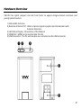
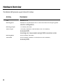
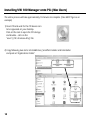
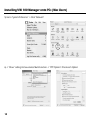
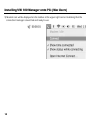
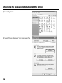
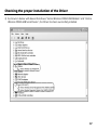
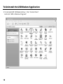
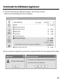
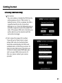
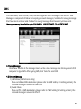
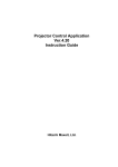
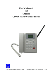
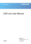
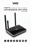
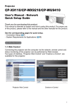
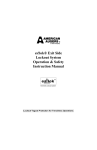
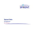
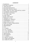
VW100
CDMA EV-DO Rev.A USB Modem
USER MANUAL
FULL FUNCTION V3.4
2
Table of Contents
Technical Specification
04
1. Product Overview
05
Package Contents
System Requirements
Features
Hardware Overview
05
06
06
07
2. Installation
09
3. Connection Manager Operation Guide
20
4. Trouble Shooting
34
Installing VW 100 Manager on to PCs (Window XP)
Installing VW 100 Manager on to PCs (MAC)
Checking the proper installation of the Driver
To Uninstall the USB Modem application
Getting Started
Connecting to the Internet
SMS
Phone Book
Call
Setting
09
10
15
18
20
22
23
25
27
29
3
Technical Specifications
Standards
CDMA EVDO 1X 450 MHz
800 MHz
1900MHz
CDMA Frequency Range
VW110
Rx: 463 ~ 468MHz
Tx: 453 ~ 458MHz
VW140
Rx: 859.64 ~ 893.37MHz
Tx: 824.64 ~ 848.37MHz
Rx: 1930 ~ 1989.95MHz
Tx: 1850 ~ 1909.95MHz
Channel Bandwidth
CDMA 1.23MHz
Storage temperature
-30 °C ~ +70 °C
4
Operating temperature
-20 °C ~ +60 °C
Humidity
5 ~ 95%
Dimension
37(W) x 76(D) x 7.5(T)mm
Interface Type
USB
LED
1 LED(Status)
Section 1. Product Overview
Package Contents
1.
2.
3.
USB Modem (Model No. VW 100)
CD (For MAC & Linux Users)
User Manual
5
System Requirements
The system requirements for using this software are summarized below:
● Recommended Specifications
CPU: Pentium III 550Mhz or higher, IBM PC-Compatible
RAM: 256MB or more
VGA: Video card with1024 x I 768 resolution and 65536 or more colors
HDD: 200MB or more hard disk space
OS: Microsoft Windows 2000 or higher (Compatible with Vista version), MAC OS, Linux
● Minimum Specifications
CPU: Pentium II 300Mhz or higher, IBM PC-Compatible
RAM: 128MB or more
VGA: Video card with 800 x 600 resolution and 256 or more colors
HDD: 100MB or more hard disk space
OS: Microsoft Windows 2000 or higher, MAC OS, Linux
Features
1.
2.
3.
4.
6
PC-Based Connection Manager Software
Top Line Color LED with Status Indicators
Receive Diversity for Maximum Range and Throughput
RUIM Support (Optional)
Hardware Overview
VW-100 has stylish compact and slim form factor to appeal design-oriented customers and
young opinion leaders.
1) Retractable Antenna
2) External Antenna Port : Able to improve signal reception and transmission with
External Antennna
3) LED Status Display : Show Status of the Modem.
4) RUIM Slot : USIM Card is inserted into this slot.
5) USB Connector : The PC and modem are connected via the USB connector.
7
Hardware Overview
The Modem LED provides a quick check of its status.
Activity
Description
OFF
Blinking Red
Modem is off
Modem is connected to the PC but no service area as per system
selection configuration
1x Mode, idle state
1x mode, modem is connected to the 1x network,
dormant/traffic
Incoming call / conversation during EVDO connection or idle
EVDO mode, idle state
EVDO mode, modem is connected to the network,
dormant/traffic
Blinking Purple
Solid Purple
Blinking Blue
Solid Blue
8
Section.2 Installation
Installing VW 100 Manager onto PCs (Window Users)
The entire process will take approximately 10 minutes to complete. (Take Windows XP as an
example)
1) Please insert the modem into the PC.
Once the modem is plugged, the installation
will be started automatically.
2) Once the installation is completed,
the Connection Manager and USB
Driver is installed into the PC.
You will see “Your new hardware is
Installed and ready to use” message.
3) Connection Manager icon will be created on
desktop in Window.
9
Installing VW 100 Manager onto PCs (Mac Users)
The entire process will take approximately 10 minutes to complete. (Take MAC Tiger as an
example)
1) Insert CD and wait for the CD device icon
to be appeared on your desktop.
Click on the icon to open the CD storage
and double – click on the
“osx-V1_09c+3-release.dmg” File.
2) Copy following two items: VertexWireless_SerialPort installer and Uninstaller
and paste at “Applications Folder”.
10
Installing VW 100 Manager onto PCs (Mac Users)
3) Installing “Vertex Wireless _ Serial port Installer”
and then restart your computer.
4) Insert your USB modem into
any available USB port,
and wait for the VWMF icon
to be appeared on your desktop.
Right click on the VWMF icon and
select Eject “VWMF”.
**note: Every time the modem is inserted into
the PC, VWMF must be ejected to use
the modem.
11
Installing VW 100 Manager onto PCs (Mac Users)
5) Go to “System Preference” -> Click “Network”
6) -> “Show” setting Vertex wireless Multi-Function. -> “PPP Options” Check each Option
12
Installing VW 100 Manager onto PCs (Mac Users)
7) -> “Modem “
Select “ Vertex Wireless Multi-Function”
8) Go to PPP and configure connection
parameters as below.
1)Service Provider :
Enter the name to be displayed on the
“Profile Name”
2) Account Name :
If required, enter the User ID for the
Network provider.
3) Password :
Enter the password for the user name.
4) Telephone No. :
Specify the phone number to which modem
will connect.
13
Installing VW 100 Manager onto PCs (Mac Users)
9) Modem icon will be displayed on the taskbar at the upper right corner. Indicating that the
connection manager is launched and ready to use.
14
Checking the proper installation of the Driver
If the Driver has been installed properly, it is possible to check the proper operation from
Control Panel (the example below is for Windows XP)
1) Start Control Panel
15
Checking the proper installation of the Driver
2) Select “System”
3) Select “Device Manager” from Hardware Tab
16
Checking the proper installation of the Driver
4) As shown in below with boxes that shows “Vertex Wireless CDMA USB Modem” and “Vertex
Wireless CDMA USB Serial Device”, the Driver has been successfully installed.
17
To Uninstall the USB Modem Application
1) To Uninstall VW 100 Modem Driver, Click “Control Panel”
And click “ADD or Remove Programs”
18
To Uninstall the USB Modem Application
2) Find VW 100 Connection Manager Program. Click Change / Remove
(Remove the VW100 Modem from the USB Port)
3) Once uninstall is completed, you must restart computer before the new setting will take effect.
19
Section 3. Connection Manager
Operation Guide
Getting Started
After plug the modem into the PC and run “Connection Manager”, the following
window is appeared. Connection Manager allows browsing internet, modifying modem
configurations.
1.1 Basic User Interface
1) Connect / Disconnect Button : Connect to the communication connection /
Disconnect from the communication connection.
2) Status Bar : Indicate the strength of the signal. More bars Indicate stronger signal.
3) Time : Indicate the Using time.
4) Unread Message: Indicates that you gave waiting text messages.
5) Voice Message : Indicates that you have voice mail messages.
6) Packet : Indicate the packet rate.
7) Manager Menu : Manager Menu allows you to conveniently move
to each Manager by one click.
20
Getting Started
1.2 Security (UIM Version Only)
1) Pin Control
You can enable or disable the PIN from the
setting (please refer to “PIN Control” in
Setting section). If Pin is enabled, the PIN is
requested each time the Connection
Manager is run. Once the following pop up
window is appeared, press the proper PIN
code. If the proper PIN code is inserted, you
will be able to use the modem with the
connection manager.
2) Fail to input the proper Pin number
If you fail up to three times to input
proper PIN code, the Authentication
would be automatically into PUK code
authentication. At this time you have 10
times to enter PUK code. If you fail up to
10 times to enter proper PUK code, you
can’t use your UIM card any more. In
this case, please contact your service
provider.
21
Connecting to the Internet
2.1 Connect
First, connect the modem into the PC then
double-click the Connection Manager icon
on the PC. If VW 100 is inserted correctly,
the LED on the Modem is blinking from
Red to Blue. Once the modem is ready,
CONNECT button will be enabled.
Click the CONNECT button to be
connected to the internet.
Once the connection is completed,
CONNECT button will be changed to
DISCONNECT button
3.2 Disconnect
Click the Disconnect button to be
disconnected from the connection.
Once the disconnection is completed,
DISCONNECT button will be changed
to CONNECT button
22
SMS
You can create, send, receive, view, edit and organize short message in this section. SMS
Manager is composed of Inbox for keeping received messages, Sent Box for saving messages
that have been sent out and Outbox for saving messages that have not yet been sent.
Message memory is available up to 500 INBOX, 100 SENT MSG, 20 OUTBOX MSG.
4.1 Send Message
Click “New” Button in the message box to write a new message. Use the key board of the
computer to type SMS. After typing SMS, click “Send” to send SMS.
4.2 Receive Message
1) UIM Inbox (UIM Version Only)
If you set UIM as SMS destination (please refer to “SMS Setting” in Setting section), the
received message is saved into UIM card.
2) Saved Inbox
If you set PC as SMS destination (please refer to “SMS Setting” in Setting section), the
received message is saved into the PC.
23
SMS
4.3 Reply Message
If you click the Reply button in the window, a new window is appeared for you to edit
the message and send it to the sender.
4.4 Reply Call
After selecting a received message from the message box, click “Call” button to make a
call to the message sender.
4.5 Forward Message
If you click the Forward button in the window, a new window is appeared for you to edit
the message and send it to another person.
4.6 Delete Message
After selecting messages from the message box, click “Delete” button to delete messages
To delete multiple data simultaneously, push “Shift or Ctrl key” and select delete
message and then click “Delete” key. The selected Inbox data is deleted at once from the
Connection manager. The deleted Inbox data cannot be restored.
4.7 Sent
Sent box list view shows all sent messages you have sent completely.
4.8 Out Box
Out box list view shows all draft messages that have not yet been sent.
4.9 Import / Export
“Export” is to send out the SMS data from the Connection Manager and save it as CVS
format file on the PC.
“Import” is to get the SMS data from the CVS file on the PC and save it to Connection
Manager.
24
Phone Book
Click Phone Book Icon to open the Phone book window. By using Phone Book, you are able
to manage the contact data in the PC or UIM (UIM version only).
Phonebook memory is available up to 500 in the PC.
5.1 Using Phonebook
You can enter/change/erase the name, type, telephone numbers.
1) Add
Click the “New” button to add a new number to the phonebook. When adding a new
number to the phone book, you can save data in the PC or UIM.
2) Editing
Click the “Modify” button to modify a name, type and number.
3) Phonebook data Move and Copy (UIM Version Only)
Click the “Move” or “Copy” button after choose the information to be moved or copied.
The phonebook data can be moved or copied from the PC to the UIM, and vice versa.
25
Phone Book
4) Delete
Click the “Delete” button to delete a phonebook from the PC or UIM.
5) Import / Export
“Export” is to send out the Phone Book data from the Connection Manager and save it
as CVS format file on the PC.
“Import” is to get the Phone Book data from the CVS file on the PC and save it to
Connection Manager.
6) SMS
Click the “SMS” button to send a message.
7) Call
Click the “Call” button to make a call.
26
Call
Click to “Call” Icon to open the call window.
1
6.1 Making Call
1) Dialing
Use the mouse cursor on the dial pad or Type numbers directly on the LCD box.
2) CLR
Press CLR button to erase last number enters, or END Button to clear all numbers.
3) SEND/END
Press the Send button to make a call to the number displayed on the LCD box. Press
END button to hang up the call.
4) Volume
Use volume key to adjust volume while you are calling.
27
Call
6.2 Accept Call
When a call comes in, Phone call window is popped up with Caller ID displayed in the
LCD. Press any button (except the END key) to receive the incoming call. Press END
button to hang up the call.
6.3 Reject Call
If you don’t want to answer the call, click the END button to reject a call.
6.4 Missed Call
If you missed phone call, display number and time you missed.
6.5 Select Contact
1) Search
You can find a contact number from the phonebook by entering information (Name
or Phone number) on the search box.
2) Call History
1> Call History Call
After selecting a call from the call history, click the “Call” button or the right button
of the mouse and select “Call”.
2> Delete
After selecting a call from the call history, click the “Delete”.
28
Setting
Click “Setting” to open the setting window to set various items.
7.1 General
You can change basic function in this section.
29
Setting
7.2 Information
You can check the software version of Firmware and Manager.
30
Setting
7.3 Pin Control
You can enable or disable the PIN feature or change the PIN number in this section. The
PIN number should be 4~5 digits numbers.
31
Setting
7.4 Profile Manager
You can create new profile by pressing New button or delete existing profile by pressing
Delete button.
1) Profile Name : Enter the name to be displayed on the “Profile Name”
2) Dial No. : Specify the phone number to which modem will connect.
3) ID : If required, enter the User ID for the network provider.
4) Password : Enter the password for the user name.
32
Setting
7.5 SMS Setting
1) Auto save : when Auto Save is enable, outgoing messages will be automatically
saved.
2) Auto erase : When Auto Erase is enabled, the oldest received messages in inbox will
be automatically deleted in case of full inbox.
3) Default destination to save SMS
: You can select where to be saved from UIM or PC using drop down menu.
33
Section 4. Troubleshooting
Below is a list of common error and possible solutions regard the use of your Wireless Modem.
Error
Solution
Initialization Fail
Out of Service Area
There was no answer
Internet connection
speed is too slow
Can not make call
Can not
connect
to the Internet
- If this condition appears, please right click the Connection
Manager icon on your system tray and click “Exit”. Then
remove and reinsert the modem and wait until your
computer “beeps” before clicking the Connection Manager
shortcut icon again.
- If this condition appears, there is no service available at this
time or Area. The network may be busy or undergoing
maintenance. Try connecting to the network at a later time,
or Moving to another location if you are outside the
enhanced.
- If this condition appears, the network may be busy. Try
and connect again at a later time.
- Please check “ Network Preference “ whether the modem
is set at 1X mode. If set at 1X mode, then the Internet is not
connected as EVDO mode.
- Please contact service provider for more information
- Please check you or other changed “Setting”.
- Please contact service provider for more information.
- Please Check “Profile Manager” of program for correct ID,
password and Service Number. For proper ID, password
and Service number, please contact service provider for
more information.
Any other trouble, please consult with service center.
34
SAR INFORMATION
THIS MODEL PHONE MEETS THE GOVERNMENT’S
REQUIREMENTS FOR EXPOSURE TO RADIO WAVES.
Your wireless phone is a radio transmitter and receiver. It is designed and
manufactured not to exceed the emission limits for exposure to radiofrequency
(RF) energy set by the Federal Communications Commission of the U.S.
Government. These limits are part of comprehensive guidelines and establish
permitted levels of RF energy for the general population. The guidelines are based
on standards that were developed by independent scientific organizations
through periodic and thorough evaluation of scientific studies. The standards
include a substantial safety margin designed to assure the safety of all persons,
regardless of age and health. The exposure standard for wireless mobile phones
employs a unit of measurement known as the Specific Absorption Rate, or SAR.
The SAR limit set by the FCC is 1.6 W/kg. * Tests for SAR are conducted with the
phone transmitting at its highest certified power level in all tested frequency
bands. Although the SAR is determined at the highest certified power level, the
actual SAR level of the phone while operating can be well below the maximum
value. This is because the phone is designed to operate at multiple power levels so
as to use only the power required to reach the network. In general, the closer you
are to a wireless base station antenna, the lower the power output. Before a
phone model is available for sale to the public, it must be tested and certified to
the FCC that it does not exceed the limit established by the government adopted
requirement for safe exposure. The tests are performed in positions and locations
(e.g., at the ear and worn on the body) as required by the FCC for each model.
The highest SAR value for this model modem when tested for use near the body,
as described in this user guide, is 1.09 W/Kg. While there may be differences
between the SAR levels of various phones and at various positions, they all meet
the government requirement for safe exposure. The FCC has granted an
35
Equipment Authorization for this model phone with all reported SAR levels
evaluated as in compliance with the FCC RF exposure guidelines. SAR information
on this model phone is on file with the FCC and can be found under the Display
Grant section of http://www.fcc.gov/oet/fccid after searching on FCC ID:
XAVVW140.
Additional information on Specific Absorption Rates (SAR) can be found on the
Cellular Telecommunications Industry Association (CTIA) web-site at
http://www.wow-com.com. * In the United States and Canada, the SAR limit for
mobile phones used by the public is 1.6 watts/kg (W/kg) averaged over one gram
of tissue. The standard incorporates a sub-stantial margin of safety to give
additional protection for the public and to account for any variations in
measurements.
Body worn operation
This device was tested in multiple notebook computer configurations with USB
port configurations for typical near-body operations with the back of the USB
Modem kept 5mm from the body. To maintain compliance with FCC RF exposure
requirements, it can be used in notebook computers with substantially similar
physical dimensions, construction, electrical and RF characteristics, and that
maintain a minimum 5mm separation distance between the user’s body and the
back of the USB Modem, including the antenna. The antenna(s) used for this USB
Modem must not be co-located or must not operate in conjunction with any other
antenna or transmitter within a host device.
36
Information to the User
“Changes or modifications not expressly approved by Vertex Wireless could void
the user’s authority to operate the equipment.”
“NOTE: This equipment has been tested and found to comply with the limits for a
Class B digital device, pursuant to part 15 of the FCC Rules. These limits are
designed to provide reasonable protection against harmful interference in a
residential installation. This equipment generates, uses and can radiate radio
frequency energy and, if not installed and used in accordance with the
instructions, may cause harmful interference to radio communications. However,
there is no guarantee that interference will not occur in a particular installation. If
this equipment does cause harmful interference to radio or television reception,
which can be determined by turning the equipment off and on, the user is
encouraged to try to correct the interference by one or more of the following
measures:
- Reorient or relocate the receiving antenna.
- Increase the separation between the equipment and receiver.
- Connect the equipment into an outlet on a circuit different from that to which
the receiver is connected.
- Consult the dealer or an experienced radio/TV technician for help. ”NOTE : This
equipment has been tested and found to comply with the limits for a class B
digital device, pursuant to part 15 of the FCC Rules. These limits are designed to
provide reasonable protection against harmful interference
37
FCC Compliance Information
This device complies with Part 15 of FCC Rules.
Operation is subject to the following two conditions:
(1) This device may not cause harmful interference, and
(2) This device must accept any interference received.
Including interference that may cause undesired operation.
38
39
www.vwireless.co.kr