1
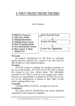
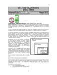
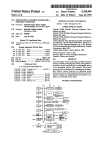
US007929740B2
(12) Ulllted States Patent
(10) Patent N0.:
Marshall et al.
(54)
US 7,929,740 B2
(45) Date of Patent:
USER DEFINABLE SCANNING PROTOCOLS
7,015,808 B1 *
3/2006 Sattler et a1. ................ .. 340/531
FOR USE WITH MAMMOGRAPHIC
7,406,150 B2 *
7/2008
Minyard et a1. . . . .
*
Inventors: Julian Marshall, Los Altos, CA (US);
1/2003 Stefanescu et a1.
2004/0114714
6/2004
2005/0114039 A1 *
600/407
. . . ..
378/37
Mark B- M” s‘mnyvale’ CA (Us);
58838132383 iii $3882 W115i“ 6‘ a1‘
233%?
Em“
I
T‘ Matuska’ Stockton’ CA (Us)
2008/0049996 A1 *
2/2008
Marshall
u e
. .et
. . . a1.
. . . . . . . ..
382/128
2008/0069416 A1*
3/2008
Luo .................. ..
(73)
Asslgneei Hologw, I110, Marlborough, MA (US)
(*)
Notice:
Subject to any disclaimer, the term ofthis
382/131
2009/0003679 A1*
1/2009
382/132
2010/0131873 A1 *
5/2010 Mejia et a1. ................. .. 715/764
WO2004/049908
*
6/2004
* cited by examiner
May 15, 2007
_
(65)
Ni et al. ....... ..
FOREIGN PATENT DOCUMENTS
WO
(21) Appl. No.: 11/803,558
382/128
2008/0279439 A1 * 11/2008 Minyard et a1.
patent is extended or adjusted under 35
USC. 1 5 4 (b) by 977 days‘
Primary Examiner * Sath V Perungavoor
_
_
(74) Attorney, Agent, or Firm * Brian J. Daiuto
Prior Publlcatlon Data
Us 2008/0049996 A1
(63)
Minyard et a1. . . . .
702/19
_
Filed:
1.1; ...;;..3;§@;
2003/0013951 A1 *
A1*
. . . .. 378/37
5/2005 Kennedy et a1.
_
(22)
.
2001181121 21, 113221
SCANNING SYSTEMS
(75)
Apr. 19, 2011
Feb. 28, 2008
(57)
_
A system and method for processing mammographic data are
_
Related U‘s‘ Apphcatlon Data
Continuation-in-part of application No, 10/998,121,
?led on Nov. 26, 2004, noW abandoned.
ABSTRACT
described. The system includes a user input/output system
adapted and con?gured to receive from a user a user-de?ned
scanning protocol that identi?es the laterality and vieW type
for each mammographic ?lm in a ?lm case to be scanned. A
(51) Int- ClG06K 9/00
Ulsl
(58)
storage system stores the user-de?ned scanning protocol for
subsequent use in scanning ?lm cases. A scanning system
(2006-01)
- - - - - - - - - - - - - - - - - - - - - - - -
Field Of ClaSSi?CatiOH Search ................. .. 382/128
mammographic ?lm, A processor then assigns laterality and
See application ?le for Complete Search history.
vieW types to the digitized versions of the mammographic
_
References Clted
?lm according to the user-de?ned scanning protocol. The
system also receives user alterations to stored scanning pro
(56)
tocols. The system can also re-assigns a case scanned accord
U.S. PATENT DOCUMENTS
5,917,929 A *
6,031,929 A *
6/1999
2/2000
Marshall et a1. .
MaitZ et a1. .... ..
6,574,629
6/2003
Cooke et a1.
B1 *
ing to one scanning protocol to another scanning protocol in
.... .. 382/128
.. 382/132
... ..
. . . . . . . . ..
1/1
6,734,880 B2 *
5/2004 Chang et a1.
6,853,857 B2 *
2/2005
Pfeiffer et a1.
.... .. 600/436
6,873,717
3/2005
Lure et a1.
. . . . ..
B2 *
6,915,154 B1*
.. 715/738
........
response to a user’ s instruction to do so. The system processes
the digitized versions according to at least one computer
aided detection (CAD) algorithm for detecting anatomical
abnormalities therein.
382/128
7/2005 Docherty et a1. ........... .. 600/431
17 Claims, 9 Drawing Sheets
User selects an existing
scanning protocol to use m
1
User loads stack of ?lms of
one or more cases into
scanner m
1
User loads initiates scanning
using selected scanning
protocol L7
User manual/y corrects ?lm
91 8
ilms correctly
scanned?
infon'nalion; or re-assigns case
to a different scanning protocol
9g)
US. Patent
Apr. 19, 2011
Sheet 2 019
US 7,929,740 B2
US. Patent
anvit.
Apr. 19, 2011
Sheet 7 019
US 7,929,740 B2
US. Patent
Apr. 19, 2011
Sheet 8 0f 9
User indicates intention to add
a new scanning protocol _7l2_
User de?nes: (a) name for new
scanning protocol; and (b)
DICOM Study Description Z13
User enters: (a) side; (b) View;
(0) modi?ers; and (d) other
information for first? lrn Z?
User adds new ?lms and
associated information as
necessary Z1_8_
User rearranges order of ?lms
in case as necessary7 .20
User saves new scanning
protocol _7__2_2
User selects which protocol will be
the default scanning protocol
Z22
US 7,929,740 B2
US. Patent
Apr. 19, 2011
Sheet 9 019
US 7,929,740 B2
User indicates intention to edit
exsisting scanning protocol
.612
User modi?es information
relating to study 513
User modi?es information for
one or more ?lms 814
User adds new ?lms or deletes
?lms from scanning protocol
m
User selects an existing
scanning protocol to use 911
User re-arranges order of films
in case as necessary 818
User loads stack of ?lms of
one or more cases into
User saves modi?ed scanning
scanner 916
protocol 53g
FIG. 8
User loads initiates scanning
using selected scanning
protocol _9_1_7
User manually corrects film
ilms correctly
scanned?
information; or re-assigns case
to a different scanning protocol
QE
FIG. 9
US 7,929,740 B2
1
2
USER DEFINABLE SCANNING PROTOCOLS
FOR USE WITH MAMMOGRAPHIC
COMPUTER-AIDED DETECTION AND FILM
SCANNING SYSTEMS
Information System) equipment directly to the radiologists’
vieWing Workstations, have not yet become common.
According to one estimate, approximately 90 percent of all
mammography systems WorldWide are still ?lm-based units,
and an equivalent percentage of all mammograms taken
yearly are ?lm-based mammograms rather than digital mam
CROSS-REFERENCE TO RELATED
APPLICATION
This patent application is a continuation-in-part of US.
Ser. No. 10/998,121, ?led Nov. 26, 2004 noW abandoned,
mograms. Because ?lm-based mammograms require digiti
Zation prior to performance of CAD algorithms, a substantial
number of Work?oW-related issues can arise.
10
One important issue relates to the scanning and identi?ca
tion process for ?lm-based mammograms. For a CAD algo
rithm to be effective, it is usually desirable for a typical 18x24
published as US 20060126909A1, Which is incorporated by
reference herein.
cm or 24x30 cm ?lm mammogram to be digitiZed at about 50
FIELD
microns of spatial resolution and about 12 bits of dynamic
range. Even using today’s scanning technologies, it can take
This patent speci?cation relates to processing medical
images. More particularly, this patent speci?cation relates to
processing ?lm-based medical images for storage, display
and/ or computer-aided detection (CAD) applications.
a commercial ?lm scanner 15-60 seconds to digitiZe one ?lm
at these resolutions, and therefore it can take 1-4 minutes to
digitiZe a typical ?lm case having 4 vieWs. A stack of 20 cases
can therefore take an hour to run through the digitiZer. At least
20
theoretically, the technologist Who placed the ?lm stack in the
scanner should be able to perform other duties While the
BACKGROUND
digitiZation is taking place. Progress has been made toWard
Computer-aided detection (CAD) generally refers to the
automation of the ?lm scanning process. One example is W0
02/ 45437 A2, Which is incorporated by reference herein,
use of computers to analyZe medical images to detect ana
tomical abnormalities therein. Sometimes used interchange
25
ably With the term computer-aided detection are the terms
computer-aided diagnosis, computer-assisted diagnosis, or
computer-assisted detection. CAD results are mainly used by
radiologists and other medical professionals as “secondary
reads” or secondary diagnoses tools. When analyZing a medi
30
Which describes automatic ?lm orientation and identi?cation
based on lead vieW marker and breast outline segmentation.
Another example is Published US Patent Application No.
US20060126909A1, Ser. No. 10/998,121, ?led on Nov. 26,
2004, Which describes a graphical status indicator having a
plurality of spatially ordered ?lm case icons that graphically
cal image, the radiologist usually makes his or her oWn ana
communicate a current state of the scanning to a technologist
lytical determinations before looking at the CAD results,
Who may be performing other duties While the digitization is
Which either verify those determinations or trigger further
taking place. HoWever, practical problems may still arise
inspection of the image. Some CAD implementations have
Which may cause the technologist to spend substantial time
used CAD results in a “concurrent reading” context in Which
the radiologists look at the CAD results at the same time that
35
they look at the images.
In order for the scanned images to be correctly identi?ed
and properly stored, each image must have information cor
In the ?eld of mammo graphy, thousands of mammo graphy
rectly associated With it. This information includes the case to
CAD systems are noW installed WorldWide, and are used to
assist radiologists in the interpretation of millions of mam
mograms per year. Mammography CAD systems are
described, for example, in US. Pat. No. 5,729,620, US. Pat.
No. 5,815,591, and US. Pat. No. 5,917,929, each ofWhich is
40
masses, and architectural distortions. The outputs of CAD
systems, generally referred to herein as CAD results, are sets
of information su?icient to communicate the locations of
anatomical abnormalities, or lesions, in a medical image, and
can also include other information such as the type of lesion,
degree of suspiciousness, and the like. CAD results are most
often communicated in the form of reduced-resolution ver
sions of the different mammographic vieWs containing anno
Which vieW). Film-based medical image scanning systems
a certain number of ?lms and the ?lms are stacked in a
particular order. This prede?ned standard scanning protocol
45
This is commonly comprised of four ?lms per study, ordered
50
as folloWs: R MLO, L MLO, R CC and L CC.
HoWever, a problem With such conventional approaches
arises When the scanning system receives a case that does not
have the same number of ?lms, the ?lms are ordered differ
55
tations that identify the location and type of potential abnor
either in ?lm format on a light box or in digital form on a
softcopy Workstation, and then revieWs the CAD results, usu
60
Work?oW processes associated With mammography,
including CAD-related Work?oW processes, implicate sub
stantial cost issues in practical clinical environments. “All
ently, and/or the vieWs do not correspond to the standard
scanning protocol set by the manufacturer. Even When auto
matic ?lm orientation and identi?cation is available, the lead
markers may be inadequate. For example, the lead marker
may be partially out of the frame or may be overlapping With
part of the breast tissue or patient label. Further, the lead
marker detection systems may especially have trouble cor
rectly identifying vieW types that are not one of the four
standard screening vieWs.
Errors in ?lm identi?cation are costly and time consuming
to correct. If the error is noticed by the technologist during the
digital” mammography environments, in Which digitally cap
tured mammograms could be automatically shepherded, With
is de?ned by the manufacturer in advance based on What the
manufacturer expects its most likely application to be. In
many cases this standard scanning protocol is chosen as the
common mammography screening case in the United States.
mality. The radiologist analyZes the original mammogram,
ally on a display monitor or a paper printout.
Which it belongs, as Well as type of image (Which side and
have conventionally assumed that each case to be scanned has
incorporated by reference herein. Mammography CAD algo
rithms analyZe digital or digitiZed images of standard mam
mographic vieWs (e.g. CC, MLO) for characteristics com
monly associated With breast cancer, such as calci?cations,
and attention in the scanning and image identi?cation pro
cess.
65
scanning process, the technologist may use a user interface to
little or no human intervention, through CAD systems and
manually identify each image. If the technologist does not
related HIS/RIS (Hospital Information System/Radiology
notice the error, the ?lm may be associated With the Wrong
US 7,929,740 B2
3
4
case. The radiologist may recognize the error during his or her
ning protocol preferably includes the number of ?lms in each
revieW, and expend valuable time making a correction.
If the technologist or technician responsible for scanning
case and the sequence of the ?lms. The system is preferably
adapted to receive user alterations to stored scanning proto
cols. The system is also preferably adapted to re-assign a case
scanned according to one scanning protocol to another scan
ning protocol in response to a user’s instruction to do so. The
the cases knoWs ahead of time that the case does not conform
to the standard scanning protocol, the information may be
manually entered. However, this may be unduly time con
suming, and in many cases such non-standard cases are sim
system is also preferably adapted to process the digitiZed
ply not scanned. If the case is not scanned at all, not only does
versions according to at least one computer aided detection
the case forego the potential bene?ts of CAD processing, the
case is also unavailable for analysis and comparison in later
therein.
(CAD) algorithm for detecting anatomical abnormalities
years, at a time When the move to all digital mammography
may have taken place at the particular medical facility.
BRIEF DESCRIPTION OF THE DRAWINGS
It is important to note that there are many Ways in Which the
FIG. 1 illustrates a CAD station in a combination ?lm
case may not conform to the manufacturer’s standard scan
ning protocol. For example, diagnostic mammography cases
based and digital mammography environment according to
commonly have more than four ?lms and include other types
embodiments;
of vieWs such as ML, LMO, LM, XCC, XCCL, XCCM, EB
and SIO for each breast. Certain types of populations may
have different imaging procedures. For example, in some
medical imaging facilities, certain ethnic populations may
have a different standard screenings. A patient my have only
FIG. 2 illustrates a display screen corresponding to the
CAD station of FIG. 1 according to embodiments;
FIG. 3 illustrates a display screen corresponding to the
20
CAD station of FIG. 1, for creating, editing and removing
scanning protocols, according to embodiments;
one breast due to a prior mastectomy. Some geographic
FIGS. 4a-b illustrate a scanning protocol template screen
regions may have different screening protocols. For example
for creating and editing scanning protocols, according to
embodiments;
in the Netherlands, after a standard four-?lm screening, in
subsequent years screening mammography cases typically
consist only of tWo ?lms: R MLO and L MLO.
Some systems alloW the user to specify a different number
of ?lms per case. One example is the SecondLook® 700
system from iCAD, Inc., Which alloWs users to specify the
number of slides per study. HoWever, if one case in a large
stack of cases has a missing ?lm, or and extra ?lm, then all of
later scanned cases in the stack can have costly identi?cation
25
scanning protocols, according to embodiments;
FIG. 6 illustrates a display screen corresponding to the
30
CAD station of FIG. 1 according to embodiments;
FIG. 7 illustrates steps involved in creating a neW scanning
protocol, according to embodiments;
FIG. 8 illustrates steps involved in editing an existing scan
ning protocol, according to embodiments; and
errors. Moreover, the user still must go through a time con
suming process for each ?lm of each case to identify the
laterality, vieW and other critical information if the cases do
not match one the standard cases supplied by the manufac
FIG. 5 illustrates a display screen corresponding to the
CAD station of FIG. 1, for creating, editing and removing
FIG. 9 illustrates steps involved in scanning ?lms using a
35
scanning protocol, according to embodiments.
DETAILED DESCRIPTION
turer.
Accordingly, it Would be desirable to provide a system for
medical ?lm digitiZation that is easier for a technologist cases
that do not correspond to a standard case that has been de?ned
FIG. 1 illustrates a CAD station 102 in a combination
40
by the manufacturer, thereby leading to cost savings and
increased productivity.
to an embodiment, including a ?lm-screen mammogram
acquisition device 104 and a digital mammogram acquisition
device 106. The digital mammogram acquisition device 106
It Would be further desirable to provide such a digitiZation
is coupled to a netWork 108, usually a netWork containing a
and/ or processing system in a manner that ?exibly accommo
dates cases of different composition, thereby increasing the
likelihood that the case is digitiZed and stored, thereby facili
tating evolution from ?lm environments to digital environ
?lm-based and digital mammography environment according
45
HIS/RIS (Hospital Information System/Radiology Informa
tion System) and a PACS (Picture Archiving and Communi
cations System).As used herein, the term “digital case” refers
to a group of mammogram images corresponding to a patient
ments.
SUMMARY
50
graphic imaging process are often termed “clients” rather
than “patients” in many clinics to denote that they are not
A system, method, and related computer program products
are provided for processing ?lm-based mammographic data.
The system preferably includes a user input/ output system
adapted and con?gured to receive from a user a user-de?ned
and acquired from a digital mammogram acquisition device.
Although asymptomatic persons undergoing the mammo
55
scanning protocol that identi?es the laterality and vieW type
symptomatic, the single term “patient” is used herein for
simplicity and clarity of description. The group of digitally
acquired mammogram images forming the digital case is
usually obtained during the same patient visit. The netWork
for each mammographic ?lm in a ?lm case to be scanned. A
108 transfers the digital cases to the CAD station 102 for
storage system is in communication With said input/ output
CAD processing. Upon successful completion of the CAD
system, and is programmed and arranged to store the user
de?ned scanning protocol for subsequent use in scanning ?lm
cases. A scanning system is preferably adapted to receive and
60
or other medical professional in conjunction With the digi
tally-acquired mammogram images. There may be more than
one digital mammogram acquisition device, each having a
different hardWare address With respect to the netWork 108.
scan a plurality of ?lm cases, generating therefrom a digitiZed
version of each mammographic ?lm. A processor in commu
nication With said storage system and said scanning system is
adapted and programmed to assign laterality and vieW types
to the digitiZed versions of the mammographic ?lm according
to the user-de?ned scanning protocol. The user-de?ned scan
processing, CAD results are then transferred over the netWork
108 to a softcopy Workstation 110 for revieW by a radiologist
65
As used herein, the term “?lm case” refers to a group of
mammogram images corresponding to a patient, the mam
mogram images being acquired using a ?lm-based mammo
US 7,929,740 B2
5
6
gram acquisition device. The group of mammogram images
forming the ?lm case is usually obtained during the same
unit 130 are combined into a single, off-the-shelf personal
computer (PC) box having an Intel Pentium IV processor With
patient visit. Illustrated in FIG. 1 are ?lm cases 112 that are
physically carried over to the CAD station 102 for scanning
hyper-threading capability and running the Linux operating
system. The user-interface, scanning control, data transfer,
and, optionally, CAD processing, and subsequently physi
and scheduling functionalities described herein can be pro
cally carried over to a ?lm revieW station 114, Which may or
grammed in C++ using the GTK toolkit and G++ compiler.
may not be con?gured to display CAD results. Upon success
ful completion of any CAD processing, CAD results are
The data storage unit 130 stores received digital cases and
scanned ?lm cases, along With their associated CAD results,
transferred over the netWork 108 to the ?lm revieW station
114. In one common scenario, the ?lm revieW station 114
comprises a motorized vieWer upon Which the ?lm cases 112
received and scanned. Cases are queued for CAD processing
in the order of priority and, Within a particular priority, in the
according to a circular buffer arrangement based on times
are loaded and synchroniZed With digital displays 116 that
order of time received or scanned. In one embodiment, all
?lm cases are assigned a medium priority, While digital cases
shoW reduced-resolution versions of the mammogram
images annotated With CAD markers and other information
derived from the CAD results. Also shoWn in FIG. 1 is a
second CAD station 140 connected to netWork 108. Accord
ing to embodiments, CAD stations 102 and 140 can be used
are assigned a high, medium, or loW priority according to
Which digital mammography acquisition device they origi
nated from, this priority level being assigned at the installa
tion time of the CAD station 102 or during a maintenance
for creation, editing, storage and use of various scanning
session thereof. In another embodiment, the CAD station 102
protocols as described in further detail herein. According to
an embodiment, scanning protocols can be created and edited
may expose more than one port, or expose more than one
20
DICOM Application Entity (AE), to the HIS/RIS netWork,
With each port or AE corresponding to a different priority
on one CAD station and then transmitted via netWork 108 for
storage and use by another CAD station. According to yet
level. In this case, each of the digital mammogram acquisition
further embodiments, stations 102 and 140 can be ?lm scan
Workstations can establish associations With the desired port
or AE according to a desired CAD processing priority deter
ning systems or ?lm scanning platforms Without CAD capa
bility such as DigitalNoWTM systems available from R2 Tech
25
nology, Inc. Thus, according these alternative embodiments,
references herein to “CAD station” refer instead to “?lm
scanning station” or “?lm scanning platform.”
Notably, the environment of FIG. 1 around the CAD station
102 is presented by Way of example only and is not intended
30
to limit the scope of the embodiments to this particular sce
nario. By Way of example, many different setups can be used
for revieWing ?lm cases and their associated CAD results,
such as simple light boxes in conjunction With paper printouts
of the CAD results. By Way of further example, different
combinations of the devices of FIG. 1 can be placed adja
35
gram case, usually just before the acquisition of the ?lm
45
50
display 122.
55
FIG. 2 illustrates a display screen 202 corresponding to the
CAD station of FIG. 1 according to an embodiment. As
described more fully in Published US Patent Application No.
display 122, Which is preferably a touchscreen display but
US20060126909A1, Ser. No. l0/998,l2l, incorporated
herein by reference, display screen 202 comprises a graphical
60
selection device. The processor 120 comprises a digitiZeruser
interface and control unit 124, a computer-aided detection
(CAD) unit 126, a scheduling unit 128, and a data storage unit
digitiZer user interface unit 124, the computer-aided detection
(CAD) unit 126, the scheduling unit 128, and the data storage
scanner reads the barcode of each separator sheet to differen
tiate the respective ?lm cases, as Well as to alloW association
betWeen that CAD case ID and the rest of the information for
that ?lm case. The technologist can preferably simply scan
the barcode on the separator sheet using the handheld barcode
scanner 132, and the information is instantly displayed on the
?lm cases 112. The ?lm scanner 118 can comprise a laser
130.
According to one embodiment, the functionalities of the
mammogram, in accordance With Whichever HIS/RIS data
base system is used at that clinic. As described in W0
02/ 43457 A2, during scanning of the ?lm stack, the ?lm
also be termed a ?lm digitiZer, for scanning and digitiZing the
Which can alternatively be implemented on a non-touch
screen monitor using an associated mouse or other pointing/
ID, Which is temporarily unique but generally re-usable
according to the number of separator sheets in use at the
clinic, is associated With a patient ID, case ID, accession
number, etc., of a particular patient for a particular mammo
environments as Well.
scanner such as the Model 2908 Laser Film DigitiZer from
Array, Inc. Alternatively, the ?lm scanner 118 can comprise a
CCD scanner or other scanner having similar ?lm scanning
capabilities as the above laser and/or CCD scanners. The
CAD station 102 further comprises a processor 120 and a
scanner 132 that facilitates convenient access to any particu
lar ?lm case based on the barcode of its case separator sheet.
scanner 118, as described in WO 02/43457 A2. The CAD case
40
applicable in ?lm-only environments and/or in digital-only
CAD station 102 comprises a ?lm scanner 118, Which can
and priority levels can thereby be assigned on a per-case
basis. Any of a variety of other prioritiZation schemes are
Within the scope of the embodiments. According to embodi
ments, data storage unit 130 also stores scanning protocols to
be used in scanning ?lm cases and assigning to each scanned
?lm laterality, vieWs and other information as described fur
ther herein.
CAD station 102 further comprises a handheld barcode
In a typical ?lm-based CAD Work?oW, a separator sheet
having a CAD case ID is placed on top of the ?rst sheet of
each ?lm case in a stack of ?lm cases being fed into the ?lm
cently to each other or integrated into the same hardWare
boxes Without departing from the scope of the embodiments.
By Way of still further example, the netWork 108 can be a
Wide-area netWork With the different nodes being distributed
throughout a city, a country, or the World. Alternatively, and
by Way of still further example, some or all of the transfer of
digital information can be achieved by physical transfer of
disks, memory sticks, or other digital media devices Without
departing from the scope of the embodiments. It is to be
appreciated that although FIG. 1 illustrates a combined ?lm/
digital environment, many of the embodiments herein are
mined at the digital mammogram acquisition Workstation,
status indicator 204 Which comprises a plurality of case icons
206, each case icon corresponding to one of the cases (?lm or
digital) received by the CAD station 102. Display 202 further
comprises a detail display area 216 Within Which the user can
vieW any of the details associated With a studies tab 220, an
65
alerts tab 224, and a controls tab 226. The alerts tab 224
invokes an alert history listing, and the tab itself shoWs a
triangular alert icon if there are any alerts present since last
US 7,929,740 B2
7
8
being cleared. The controls tab 226 allows access to a variety
of maintenance and con?guration screens, and the tab itself
scanning protocol by means of Move Up button and Move
DoWn button as described beloW. BeloW selection area 234,
the case composition 240 is preferably displayed in terms of
the laterality and vieWs listed as they are expected to be
loaded into the scanner, With the top ?lm listed on the top.
FIG. 3 illustrates display screen 202 corresponding to the
shoWs a small Wrench icon if there is something requiring
maintenance-related attention (e. g., it is time to perform peri
odic calibration or other maintenance activity, or a diagnostic
error occurred on startup, etc.). According to an embodiment,
controls tab 226 is also used to access the facility for creating,
CAD station of FIG. 1, for creating, editing and removing
scanning protocols, according to embodiments. The user ini
tiates the process by touching the controls tab 226. Controls
editing and deleting scanning protocols, as described more
fully beloW.
selection area 302 is shoWn With various control options that
The studies tab 220 causes the details of the currently
selected case to be displayed, including text details 227, a
patient ?ash area 228 containing the ?ash of a scanned ?lm,
are touch screen selectable. The user selects the scanning
and a thumbnail area 230 shoWing thumbnails of mammo
selecting scanning controls 304, the system generates and
displays a list of existing scanning protocols in scanning
control 304 from the list in controls selection area 302. By
graphic vieWs that have been scanned and/ or processed thus
far. The display 202 further comprises a search area 232
protocol list area 306. Note that the scanning protocols listed
in area 306 preferably corresponds to the list displayed in
alloWing searching by any of a variety of criteria (e.g., patient
ID, patient name, CAD case ID, accession number, etc.).
protocol selection area 234. The user indicates the intention to
create a neW scanning protocol by touching neW button 308.
Also shoWn in FIG. 3 is Edit button 310, used to indicate the
Patient ID area 233 alloWs for the display of the patient ID. A
scanning protocol selection area 234 alloWs the user to select
betWeen several different scanning protocols. As used herein,
20
user’s intention to edit and existing scanning protocol.
the term “scanning protocol” refers to a de?ned composition
Remove button 312 is used to indicate the user’s intention to
of ?lms in a stack of ?lms loaded in the scanner feeder. The
scanner assumes that the ?lms Will be separated in to cases,
permanently delete an existing scanning protocol. After
each having the composition according to the selected scan
ning protocol. As used herein, the term “user” refers to a lead
remove button 312 is touched there is preferably a Warning
WindoW displayed With text such as “You are about to remove
25
technician, technician or other scanner operator that is gen
scanning protocols. The scanning protocol at the top of the list
erally employed by or otherWise associated With the medical
facility Where the scanning and/ or CAD systems are installed
and operated. The term “user” is not intended to refer to
employees, contractors or agents of the manufacturer and/or
is preferably alWays the default scanning protocol.
FIGS. 4a-b illustrate scanning protocol template screen
30
create and/or edit a scanning protocol, scanning protocol
According to an embodiment, display screen 202 includes
template screen 402 is preferably displayed as shoWn in FIG.
4a. Screen 402 includes scanning protocol name area 404
a number of prede?ned scanning protocols. Scanning proto
col selection area 234 is shoWn including six different scan
35
marker and breast outline segmentation is performed (see
can preferably use this ?eld to edit the name of an existing
WO 02/43457 A2, supra). “Auto” assumes that (1) there are
likely to be four ?lms per study, (2) the ?lms are taken using
40
LCC, RMLO and LMLO). The “Any” scanning protocol
makes no assumption about What ?lms are in the cases. This
scanning protocol requires manual identi?cation of each
image after scanning. Other scanning protocols can be pro
Which either displays the name of the protocol being edited,
or in the case Where a neW protocol is being created, alloWs
the entry of the name of the neW scanning protocol. The user
matic ?lm orientation and identi?cation based on lead vieW
recogniZed lead markers for correct identi?cation, the (3) the
cases consist of the four standard screening vieWs (RCC,
402, for creating and editing scanning protocols, according to
embodiments. In response to receiving the user’s intention to
designers of the scanning and/or CAD systems.
ning protocols. The “Auto” scanning protocol provides auto
a scanning protocol. Are you sure?” Move Up button 314 and
Move DoWn button 316 are used for re-ordering the list of
scanning protocol. The name of the scanning protocol in area
404 is preferably identical to the name used in the scanning
protocol selection area 234 shoWn and described With respect
to FIG. 2. Also provided in screen 402 is a DICOM study
description area 430. DICOM study description 430 is used
for entry, display and editing of the DICOM study descrip
45
tion, Which is preferably used by Workstations to determine
vided as listed in the Table 1, however according to embodi
hoW to display (or hang) the digitiZed ?lm images When using
ments described herein, the user can edit, delete and create
a system such as DigitialNoWTM from R2 Technology, a
Hologic® company. For users Who make use of the DICOM
neW scanning protocols in order to customiZe and improve the
study description ?eld, the DICOM study description and the
scanning process.
50
TABLE 1
Scanning Protocol
Composition
Screening
Uni Right
RCC, LCC, RMLO, LMLO
RCC, RMLO, RXCC
Uni Left
LCC, LMLO, LXCC
Screening Imp
scanning protocol name can be the same, or the scanning
protocol name can be an abbreviation of the DICOM study
description or any other unique string. Film list area 406 is
used to display the order of the ?lms that Will be included for
each case in the scanning protocol. In the example of FIG. 4a,
55
RCC, LCC, RMLO, LMLO,
RCCID, LCCID, RMLOID, LMLOID
one ?lm is shoWn that is currently identi?ed as L CC. The user
indicates an intention to modify the settings for a ?lm in the
case by selecting the ?lm, such as L CC ?lm 408, in ?lm list
area 406. NeW button 410 alloWs for the user to add neW ?lms
to the protocol for the case. Remove button 412 alloWs for the
The user preferably selects the desired scanning protocol
60
selection, the selected scanning protocol is highlighted to
indicate Which protocol Will be used for scanning. If no user
selection is made, a default scanning protocol is used for the
scanning, Which is preferably the ?rst scanning protocol
listed in selection area 234. The ?rst scanning protocol listed
can be changed by the user in order to change the default
user to delete a selected ?lm. The name of the current ?lm is
preferably displayed in area 414, Which corresponds to the
?lm selected and preferably highlighted, in area 406. Area
using the touch screen on protocol selection area 234. After
65
416 is used to identify the ?lm as left, right or both. Area 418
is used to identify the vieW type of the ?lm. Area 420 is used
to add modi?ers to the ?lm, and Area 422 used to indicate
When the ?lm is a partial vieW and/or there is an implant
present. FIG. 4b illustrates an example With a total of ?ve
US 7,929,740 B2
9
10
?lms added using new button 410 and the identifying ?elds
416, 418, 420 and 422. Film “L M S MLO” 440 is currently
highlighted and is shoWn in area 414. Up and doWn buttons
saves the neWly created scanning protocol. In the example of
FIGS. 4a-b, this is accomplished using OK button 436.
424 and 426 are used to re-arrange the order of the ?lms in the
ning protocol, according to embodiments. In step 812, the
scanning protocol, and as displayed in ?lm list area 406. If the
user is not satis?ed With changes made, the user has the option
user indicates an intention to edit and existing scanning pro
FIG. 8 illustrates steps involved in editing an existing scan
tocol. In the example of FIG. 3, this is accomplished by
selecting controls tab 226, scanning control 304, and then edit
of cancelling all the current changes by touching the cancel
button 3 1 0. In step 813, the user enters information relating to
the study to be scanned. In the example of FIGS. 411-!) this is
button 432. If the user is satis?ed With the changes made, then
the OK button 436 is touched and the edited or neW scanning
accomplished by entering the scanning protocol name in area
protocol is saved.
404 and study description in area 430. In step 814, the user
FIG. 5 illustrates display screen 202 corresponding to the
modi?es information for one or more ?lms. In the example of
CAD station of FIG. 1, for creating, editing and removing
scanning protocols, according to embodiments. In particular,
FIGS. 4a-b, this is accomplished by entering or altering the
information in ?elds 416, 418, 420 and 422 for each ?lm. In
FIG. 5 shoWs a vieW of screen 202 With a neWly added
step 816, the user adds neW ?lms or deletes ?lms from the
scanning protocol 506 named “Diag L” in scanning protocol
scanning protocol. In the example of FIGS. 4a-b, this is
list area 306. The neW scanning protocol is also preferably
displayed in protocol selection area 234. When a protocol is
selected in area 306, the order of ?lms in the case is displayed
in area 512.
20
According to an embodiment, the default scanning proto
col can be assigned by re-arranging the order of the scanning
the top being scanned ?rst. In the example of FIGS. 4a-b,
selecting ?lms in area 406 and up and doWn buttons 424 and
426 are used to accomplish this step. In step 820, the user
protocol list in area 306 using the move up and move doWn
buttons 314 and 316 respectively. For example the neWly
created scanning protocol 510 can be assigned as the default
25
force button 602 if provided. Force button 602 is used to
override the scanning protocol used to originally scan the case
and instead assign another scanning protocol to the case. For
example, if the “Auto” scanning protocol Was used for scan
ning the case shoWn in FIG. 6, and in fact the case should have
the user indicates an intention to scan a neW case or a multiple
cases, and selects an existing scanning protocol to use. In the
example of FIG. 2, this is accomplished by choosing and
30
or more cases into the scanner. This is preferably accom
35
plished by placing a separator sheet on the top of each case, as
more fully described in WO 02/45437A2. The stack of ?lms
is positioned in the input tray of the scanner feeder. In step
917, the user initiates scanning using the selected scanning
protocol. This is preferably accomplished by the user press
40
ing the start button on display 202. If no scanning protocol
Was selected in step 914, then the default scanning protocol
Will be used. In step 918, the user monitors the scanning
process as described more fully in Published US PatentAppli
cation No. US20060126909A1, Ser. No. 10/998,121. If an
error is detected in the scanning process, in step 920, the user
can manually correct the ?lm information using a screen that
selected scanning protocol. This feature advantageously pro
vides for quick and e?icient identi?cation of ?lms by avoid
ing a manual identi?cation process.
FIG. 7 illustrates steps involved in creating a neW scanning
selecting a scanning protocol from protocol selection area
234. In step 916, the user loads a stack of ?lms making up one
been scanned using the “Diag L” scanning protocol, the user
can select “Diag L” from protocol selection area 234, and
then touch force button 602. The system Will retroactively
assign the selected scanning protocol for the current case, and
identify all the ?lms in the case according to the neWly
saves the modi?ed scanning protocol.
FIG. 9 illustrates steps involved in scanning ?lms using a
scanning protocol, according to embodiments. In step 914,
by selecting it and repeatedly touching move up button 314
until protocol 510 is at the top of the list.
FIG. 6 illustrates a display screen 202 corresponding to the
CAD station of FIG. 1 according to an embodiment. The
embodiment illustrated in FIG. 6 is similar to the screen
shoWn and described With respect to FIG. 2, except that a
accomplished using neW and remove buttons 410 and 412
respectively. In step 818, the user re-arranges the order of the
?lms of the case as necessary to correspond to the expected
stack order of the ?lms as Will be loaded in the scanner, With
45
is similar to that shoWn in FIGS. 4a-b, or the user can re
protocol, according to embodiments. In step 712, the user
assign the case to a different scanning protocol, as shoWn and
indicates an intention to add a neW scanning protocol. In the
described With respect to FIG. 6. In step 922, the scanning
process is completed.
example of FIG. 3, this is accomplished by selecting controls
Whereas many alterations and modi?cations of the present
tab 226, scanning control 304, and then neW button 308. In
step 714, the user de?nes a name for the neW scanning pro
50
invention Will no doubt become apparent to a person of ordi
nary skill in the art after having read the foregoing descrip
tion, it is to be understood that the particular embodiments
tocol and optionally a DICOM study description. In the
example of FIGS. 4a-b, this is accomplished by entering the
information in areas 404 and 430. In step 716, the user enters
shoWn and described by Way of illustration are in no Way
the identi?cation information such as laterality (side), vieW,
intended to be considered limiting. It is to be appreciated, for
example, that several of the user interface embodiments
modi?ers, etc. associated With the ?rst ?lm in the case. In the
55
example of FIGS. 4a-b, this is accomplished by entering the
described supra are applicable in a digital-only mammo
information in ?elds 416, 418, 420 and 422. In step 718, neW
graphic environment Where easy monitoring and control or
?lms are added as necessary and the identi?cation informa
the digital case receiving, processing, and dispensing is
tion is added for each neW ?lm. In the example of FIGS. 4a-b.
This is accomplished by selecting neW button 410, and then
entering information in ?elds 416, 418, 420 and 422 for each
60
neW ?lm. In step 720, the user re-arranges the order of the
?lms of the case as necessary to correspond to the expected
stack order of the ?lms as Will be loaded in the scanner, With
the top being scanned ?rst. In the example of FIGS. 4a-b,
selecting ?lms in area 406 and up and doWn buttons 424 and
426 are used to accomplish this step. In step 722, the user
desired. The graphical status indicator can be horizontally
oriented, diagonally oriented, etc ., Without departing from the
scope of the embodiments. Further types of temporal changes
in icon appearance other than blinking, such as rotating icons,
can be used as visual textures or cues Without departing from
65
the scope of the embodiments. Even further, although par
ticular reference is made to digital x-ray mammography, the
scope of the embodiments includes any of a variety of medi
cal imaging modalities that, either presently or prospectively,
US 7,929,740 B2
11
12
are amenable to CAD analysis and/or softcopy display.
8. A system according to claim 1 Wherein said user input/
output system and said storage system are located in different
Present or prospective examples including computerized
tomography (CT) imaging, magnetic resonance imaging
(MRI), positron emission tomography (PET), single-photon
facilities and said communication is made via a Wide-area
netWork.
9. A system according to claim 1 Wherein said processor is
emission computed tomography (SPECT), and ultrasound, as
further adapted to process the digitiZed versions according to
at least one computer aided detection (CAD) algorithm for
detecting anatomical abnormalities therein.
10. A method for processing ?lm-based mammographic
Well as less conventional medical imaging modalities such as
therrnography, electrical conductivity-based modalities, etc.
Therefore, reference to the details of the embodiments are not
intended to limit their scope, Which is limited only by the
data, comprising the steps of:
scope of the claims set forth beloW.
receiving from a user a user-de?ned scanning protocol
identifying at least a vieW type for one or more mammo
What is claimed is:
graphic ?lms in a ?lm case to be scanned using the
1. A system for processing ?lm-based mammographic
user-de?ned scanning protocol;
data, comprising:
storing the user-de?ned scanning protocol in a storage
a user input/output system adapted and con?gured to
system;
receive from a user a user-de?ned scanning protocol
scanning a ?lm case comprising plurality of mammo
graphic ?lms and generating therefrom a digitiZed ver
identifying at least a vieW type for one or more mammo
sion of each mammographic ?lm; and
graphic ?lms in a ?lm case to be scanned using the
user-de?ned scanning protocol;
20
the mammographic ?lms according to the user-de?ned
a storage system in communication With said input/ output
system, programmed and arranged to store the user
de?ned scanning protocol for subsequent use in scan
ning ?lm cases;
a scanning system adapted to receive and scan a plurality of
?lm cases, generating therefrom a digitiZed version of
scanning protocol;
Wherein said storage system stores a plurality of scanning
protocols, and Wherein said method further comprises
25
receiving a user’ s instruction to re-assign a case scanned
according to a ?rst scanning protocol to a second scan
ning protocol, Wherein said step of assigning automati
cally assigns the vieW type to each digitiZed version
each mammographic ?lm; and
a processor in communication With said storage system and
said scanning system, adapted and programmed to
assign vieW types to one or more digitiZed versions of
assigning vieW types to one or more digitiZed versions of
according to the second scanning protocol in response to
30
the mammographic ?lm according to the user-de?ned
scanning protocol;
the user’s instruction.
11. A method according to claim 10, Wherein the user
de?ned scanning protocol further identi?es the number of
Wherein said storage system stores a plurality of scanning
protocols and said user input/output system is further adapted
?lms, the sequence of ?lms and the laterality of each mam
mographic ?lm in the ?lm case to be scanned using the
to receive a user’s instruction to re-assign a case scanned 35
user-de?ned scanning protocol, and said step of assigning
according to a ?rst scanning protocol to a second scanning
further comprises assigning a laterality to each digitiZed ver
sion of the mammographic ?lms according to the user-de
protocol, said processor further adapted to automatically
assign the vieW type to each digitiZed version according to the
second scanning protocol in response to the user’s instruc
tion.
2. A system according to claim 1, Wherein the user-de?ned
?ned scanning protocol.
12.A method according to claim 10, further comprising the
40
scanning protocols stored in said storage system.
scanning protocol further identi?es the laterality of each
mammographic ?lm in the ?lm case to be scanned using the
user-de?ned scanning protocol, and said processor is further
adapted to assign laterality to each digitiZed version of the
mammographic ?lms according to the user-de?ned scanning
step of receiving from the user alterations to one or more
45
13. A method according to claim 10, said method further
comprising the step of receiving from the user a user’s selec
tion of Which scanning protocol to use for scanning one or
more ?lm cases, and Wherein said step of assigning uses the
user’ s selection if available and a default scanning protocol if
protocol.
no user’s selection is available.
3. A system according to claim 1, Wherein the user-de?ned
scanning protocol further de?nes the number of ?lms and the
14. A method according to claim 10 further comprising the
step of processing the digitiZed versions according to at least
one computer aided detection (CAD) algorithm for detecting
sequence of ?lms for each case to be scanned using the
50
user-de?ned scanning protocol.
4. A system according to claim 1, Wherein said user input/
output system is further adapted and con?gured to receive a
user-de?ned name for the user-de?ned scanning protocol.
5. A system according to claim 1, Wherein said user input/
output system is further adapted to receive alterations to one
or more scanning protocols stored in said storage system.
6. A system according to claim 1, Wherein said storage
system stores a plurality of scanning protocols and said user
input/output system is further adapted to receive a user’s
selection of Which scanning protocol to use for scanning one
anatomical abnormalities therein.
15. A method for processing ?lm-based mammographic
data, comprising the steps of:
scanning a plurality of mammographic ?lm cases, each
55
erating therefrom a digitiZed version of each mammo
graphic ?lm; and
60
default scanning protocol in cases Where there is no user
selection received.
assigning laterality and vieW types to each digitiZed ver
sion of the mammographic ?lms according to a stored
user-de?ned scanning protocol, the user-de?ned scan
ning protocol having been received from a user and
identifying a laterality and a vieW type for each mam
mographic ?lm in each ?lm case
Wherein a storage system stores a plurality of scanning
or more ?lm cases.
7. A system according to claim 6 Wherein said user input/
output system is further adapted to receive a user’s selection
of Which of the plurality of scanning protocols is be used as a
comprising plurality of mammographic ?lms, and gen
65
protocols, the method further comprising receiving a
user’s instruction to re-assign a case scanned according
to a ?rst scanning protocol to a second scanning proto
US 7,929,740 B2
13
14
col, wherein said step of assigning automatically assigns
of assigning uses the user’s selection of scanning protocol if
the laterality and VieW type to each digitized Version
according to the second scanning protocol in response to
available and a default scanning protocol if no user’s selec
tion is available.
the user’s instruction.
16. A method according to claim 15, said plurality of scan
ning protocols comprising one or more user-de?ned scanning
protocols and one or more manufacturer-de?ned scanning
protocols, the method further comprising the step of receiving
from the user a user’ s selection of Which stored scanning
protocol to use for said step of scanning, and Wherein said step
17. A method according to claim 15, further comprising the
step of processing the digitiZed Versions according to at least
one computer aided detection (CAD) algorithm for detecting
anatomical abnormalities therein.