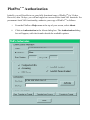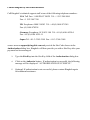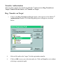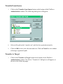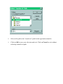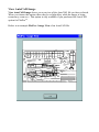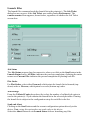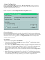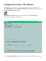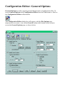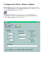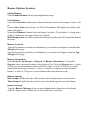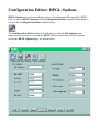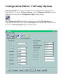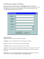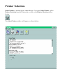
1
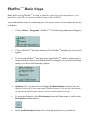
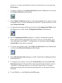
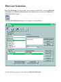
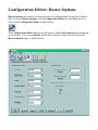
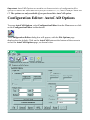
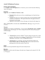
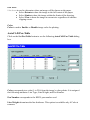
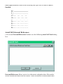
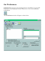
PlotProTM
User Manual
VERSION 2.1
RINGDALE
Connecting People and Information
PlotProTM 2.1
The software described in this book is furnished under a license agreement and may be
used only in accordance with the terms of the agreement.
Copyright © 1999 by Ringdale, Inc. This software is protected by copyright law and
international copyright treaty.
Printed in the United States of America.
All rights reserved. Except as permitted under the United States Copyright Act of
1976, no part of this manual may be reproduced or distributed in any form or by any
means, or stored in a data base or retrieval system without the prior written permission
of Ringdale.
The information in this manual is subject to change without notice and, except for the
warranty, does not represent a commitment expressed or implied on the part of
Ringdale. Ringdale cannot be held liable for any mistakes in this manual and reserves
the right to make changes to this document or the product.
Notices
PlotProTM is a trademark of Ringdale, Inc.
Windows and NT are trademarks of Microsoft Corporation.
Microsoft is a registered trademark of Microsoft Corporation.
UNIX is a registered trademark of UNIX System Laboratories.
PostScript is a registered trademark of Adobe Systems.
HPGL is a trademark of Hewlett-Packard, Inc.
CalComp is a trademark of CalComp, Inc.
AutoCAD is a registered trademark of AutoDesk, Inc.
Apple and Macintosh are registered trademarks of Apple Computer, Inc.
Hewlett-Packard and HP are registered trademarks of Hewlett-Packard, Inc.
Ringdale License Agreement
This software is protected by copyright law and international copyright treaty. You may
make as many copies of PlotProTM as you need for your personal use. Making copies,
however, does not grant authorization. For information on purchasing authorizations,
contact Ringdale, Inc. To make copies for any other reason, you must have the prior
written permission of Ringdale, Inc.
Activating Optional Features:
Each copy you make of PlotProTM will have standard features but no optional features
such as AutoCAD support. To activate optional features, you must purchase a key
code from Ringdale. A unique key code must be obtained for each copy that you want
optional features for. You can purchase key codes for some or all optional features.
Making a copy of PlotProTM after the purchase of a key code will not copy the optional
features. A new key code must be purchased to activate any optional features in any
new copies you make of PlotProTM.
Transferring PlotProTM to another machine after the purchase of a key code does not
disable the key code. For more information, see the “Transfer Authorization” and
“Transfer to Target” sections in PlotPro Authorization.
Ringdale Limited Warranty
Ringdale, Inc., warrants that the media on which this software is distributed will be
free from defects for a period of sixty (60) days from the date of delivery of the
Software to you. Your sole remedy in event of a breach of this warranty will be that
Ringdale will, at its option, replace any defective media returned to Ringdale within the
warranty period or refund the money you paid for the Software. Ringdale does not
warrant that the Software will meet your requirements or that operation of the Software
will be uninterrupted or that the Software will be error-free.
THE ABOVE WARRANTY IS EXCLUSIVE AND IN LIEU OF ALL OTHER
WARRANTIES, WHETHER EXPRESS OR IMPLIED, INCLUDING THE IMPLIED
WARRANTIES OF MERCHANTABILITY, FITNESS FOR A PARTICULAR
PURPOSE AND NONINFRINGEMENT.
THIS WARRANTY GIVES YOU SPECIFIC LEGAL RIGHTS. YOU MAY HAVE
OTHER RIGHTS, WHICH VARY FROM STATE TO STATE AND COUNTRY TO
COUNTRY.
Disclaimer of damages
REGARDLESS OF WHETHER ANY REMEDY SET FORTH HEREIN FAILS OF
ITS ESSENTIAL PURPOSE, IN NO EVENT WILL RINGDALE BE LIABLE TO
YOU FOR ANY SPECIAL, CONSEQUENTIAL, INDIRECT OR SIMILAR
DAMAGES, INCLUDING ANY LOST PROFITS OR LOST DATA ARISING OUT
OF THE USE OR INABILITY TO USE THE SOFTWARE EVEN IF RINGDALE
HAS BEEN ADVISED OF THE POSSIBILITY OF SUCH DAMAGES.
SOME STATES DO NOT ALLOW THE LIMITATION OR EXCLUSION OF
LIABILITY FOR INCIDENTAL OR CONSEQUENTIAL DAMAGES SO THE
ABOVE LIMITATION OR EXCLUSION MAY NOT APPLY TO YOU.
IN NO CASE SHALL RINGDALE’ LIABILITY EXCEED THE PURCHASE PRICE
FOR THE SOFTWARE.
The disclaimers and limitations set forth above will apply regardless of whether you
accept the Software.
Contents
License Agreement ............................................. Page 3
Introduction ........................................................ Page 9
Installing PlotProTM ............................................. Page 11
PlotProTM Authorization ....................................... Page 13
DDE (Dynamic Data Exchange) ......................... Page 19
PlotProTM Basic Steps .......................................... Page 21
Plot List Selection ............................................... Page 23
Configuration Editor: File Options ...................... Page 29
Configuration Editor: General Options ................ Page 31
Configuration Editor: Banner Options ................. Page 33
Configuration Editor: HPGL Options .................. Page 35
Configuration Editor: Calcomp Options .............. Page 37
Configuration Editor: Raster Options .................. Page 41
Configuration Editor: AutoCAD Options ............ Page 45
Set Preferences ................................................... Page 51
Printer Selection ................................................. Page 55
Contents, Continued
Getting Help In PlotProTM .................................... Page 57
Troubleshooting PlotProTM ................................... Page 59
Contacting Ringdale ........................................... Page 57
Introduction to PlotProTM
The following is a brief description of the features and capabilities of PlotProTM.
Network Plot Management Software
PlotProTM from RINGDALE is a Windows 95/98/NT application that gives you
control over plot and document files. Spooling and management features
combined with the popular Windows interface style make PlotProTM a snap to
use. PlotProTM is designed to work best with devices using JRL controller
technology and devices supporting HPGL or HPGL-2. PlotProTM can also handle
multiple printers simultaneously.
AutoCAD Direct Viewing and Printing
PlotProTM is an ideal utility for AutoCAD users. It allows direct previewing and
plotting of DWG and DXF files (including all X-references) for AutoCAD 12,
13, and 14 (up to the 4.2 Specification) to a variety of output devices.
Banners, Scaling, Rotation, Batch Plotting, Collation, ...
Plot customization features include scaling, rotation, and other format options.
Users can also create banners or information tags printed in the margins of
documents. PlotProTM plots job sets (batches) with electronic collation at the
click of a mouse.
Accounting feature Distributes Costs
User accounts can be maintained by PlotProTM in a file on the Windows NT
server so that an organization can distribute the cost of printing to the specific
departments and users of the facilities.
Paper Finishing with Document Folder
PlotProTM allows setup of a Ringdale Document Folder when the unit is attached
to a Ringdale Plotter. Besides powering on or off the Document Folder, you can
also choose from any of the available fold styles currently setup on the unit
including landscape and portrait folds for A to E size (or A4 to A0 size) documents. Fold styles include Accordion/Fan folding and Bookfolding as well as Zand C- crossfolding.
Customized Automation
Save time by allowing users to customize and automate the output of documents.
PlotProTM takes all the usual hassle out of accounting and set up for plots and
other documents. No more network headaches going back and forth between
rooms because a document comes out wrong. PlotProTM takes care of it all so
you can feel confident about how hardcopies will look.
Remote Control from Other Applications
By acting as a Windows DDE server, PlotProTM can be controlled from Windows
by popular Document Management and Data Base packages. Adding simple
scripts also provides batch plotting and AutoCAD direct plotting capabilities to
these other applications.
For PlotProTM operating instructions, see the topic PlotProTM Basic Steps.
Installing PlotProTM
Install PlotProTM on a computer connected to the network and running either
Windows 95/98 or Windows NT.
Floppy Disk Installation
To install PlotProTM using the set of four floppy disks:
1
Insert Disk 1 for PlotProTM into Drive A.
2
From Windows NT Program Manager, choose Run from the File Menu.
-orFrom Windows 95/98 taskbar, select Start and then choose Run.
3
Enter a:\setup in the edit box and choose OK.
4
Follow the on screen instructions from the PlotProTM setup program. The
program will prompt you to insert and remove specific disks at various stages
during the installation process
Installation is complete.
CD Installation on Windows 95/98 and NT 4.0
Important: Before installing PlotProTM ensure that you exit all Windows programs.
1
Insert the PlotProTM CD-ROM in your drive and wait a few moments.
2
You will be presented with a message window telling you that you are
installing PlotProTM.
3
Click Next to continue. After a few moments a window appears showing the
license agreement.
4
If you agree to the terms of the license agreement, select Yes. If you do not
agree, select No and the installation will be cancelled.
CD Installation Continued
5
Click on Next to continue. The Select Program Folder window appears,
displaying the default directory for PlotProTM as:
C:\Program Files\PlotPro\
You have the option of selecting another folder for PlotProTM installation.
6
When a program folder has been selected, click on Next to continue.
7
Installshield will now automatically copy the files to your hard drive. A
screen will appear, informing you that PlotProTM has been successfully
installed. Click on OK.
8
The final window gives you the option of restarting your computer without
running through the close down procedure. Remove the CD from the drive,
check that Restart my computer now is selected and click on Finish. After
the re-boot is finished PlotProTM installation will be complete.
PlotProTM Authorization
Initially, you will be able to use your fully functional copy of PlotProTM for 30 days.
However, after 30 days, you will no longer have access to the AutoCAD functions. For
permanent AutoCAD functionality, authorize your copy of PlotProTM as follows:
1
From the PlotProTM Help menu at the top of your screen, select About.
2
Click on Authorization in the About dialog box. The Authorization dialog
box will appear, with check marks beside the available options:
Contact Ringdale by one of these methods:
Call Ringdale’s technical support staff at one of the following telephone numbers:
USA Toll Free: 1-800 PLOT NOW Tel: +1 512 288 9080
Fax: +1 512 288 7210
UK Freephone: 0800 214503 Tel: +44 (0) 1444 871349
Fax: (0) 1444 870228
Germany Freephone: 0130 825 188 Tel: +49 (0) 6106 8529-0
Fax: +49 (0) 6106 8529-11
Japan Tel: +81-3-3345-2189 Fax: +81-3-3344-3949
Send e-mail to [email protected] and provide the Site Code shown in the
Authorization dialog box. Ringdale will then provide you with a Site Key after your
payment has been arranged.
3
Type the Site Key into the Site Key field of the Authorization dialog box.
4
Click on the Authorize button. If authorization is successful, the following
message will be displayed: “AUTHORIZATION SUCCESSFUL”.
5
Optional: If authorization is not successful, please contact Ringdale again
for additional assistance.
Transfer Authorization
There are three options for transferring PlotProTM authorization: Reg. Transfer on
Target, Transfer From Source, and Transfer to Target.
Reg. Transfer on Target
1
Click on the Reg. Transfer on Target button at the bottom of the PlotProTM
Authorization window. The following dialog box will appear, as shown
below:
2
Select a file path as the “target” for the registration transfer.
3
Click on OK to save your selection and exit. Click on Cancel to exit without
selecting a registration path.
Transfer From Source
1
Click on the Transfer from Source button at the bottom of the PlotProTM
Authorization window. The following dialog box will appear:
2
Select a file path as the “transfer out” path for the registration transfer.
3
Click on OK to save your selection and exit. Click on Cancel to exit without
selecting a registration path.
Transfer to Target
1
Click on the Transfer to Target button at the bottom of the PlotProTM
Authorization window. The Select “Transfer In” dialog box will appear, as
shown on the following page:
2
Select a file path as the “transfer in” path for the registration transfer.
3
Click on OK to save your selection and exit. Click on Cancel to exit without
selecting a transfer in path.
DDE (Dynamic Data Exchange)
DDE (Dynamic Data Exchange) allows programs running concurrently to communicate, one program acting as a server and the other as a client.
PlotProTM registers itself as a DDE server with the service name PlotProTM. To make
use of DDE commands, you must use an application that supports DDE client operations. The DDE client can then send data to PlotProTM using the following DDE
commands:
NOTE: The format of the DDE commands depends on the format used by the client
application.
DDE Connect Command
This command establishes communications with PlotProTM using PlotProTM as the
service name and LaunchList as the topic.
DDE Poke Command
This command sends data to PlotProTM.
To add a plot file to the launch list, use Poke to send the PlotProTM command AddFile
along with the full path of a plot file that you want added to the launch list. For
example, a path might be C:\CADimages\drawing.dwg.
After adding a plot file to the launch list, you may also want to assign a configuration
file to that plot file. To assign a configuration file to the last plot file in the launch list,
use Poke to send the AssignConfig command along with the full path of a configuration file that you want to assign. For example, a path might be
C:\PlotProTM\ConfigurationFiles\Config1.cfg. If you do not use the
AssignConfig command, the current configuration settings in PlotProTM will be
assigned to the plot file.
DDE Execute Command
This command instructs PlotProTM to perform an operation.
To clear the launch list, use Execute to send the command ClearLaunchList to
PlotProTM. PlotProTM will then clear the launch list of all plot files.
To open the Launch Files dialog box, use Execute to send the command
LaunchDialog to PlotProTM. From the Launch Files dialog box, you can adjust the
launch settings and select the Send button to launch the files from the launch list to
the selected printer.
To launch the files without opening the Launch Files dialog box, use Execute to send
the command LaunchSend to PlotProTM. PlotProTM will then launch all of the plot
files in the launch list to the selected printer.
PlotProTM Basic Steps
Note: Before using PlotProTM to send, or launch, a plot file to an output device, you
must have a plot file in a printer usable format, such as HPGL.
The recommended steps for launching plot files from PlotProTM to an output device are
as follows:
1
Click on Start > Programs > PlotProTM. The following submenu will appear:
2
Click on PlotProTM from the submenu. The PlotProTM introductory screen will
appear.
3
To access the PlotProTM functions from any PlotProTM window, either select a
menu option or click on a toolbar button. For example, if you select the View
menu you will see the following options:
4
Optional: The check mark beside Large Toolbar Buttons indicates that the
option is selected. If you want small toolbar buttons, click on the check mark
so that the option becomes deselected (no check mark showing).
5
To setup preferences, select Preferences from the View menu or click on the
Preferences toolbar button:
6
In the Set Preferences dialog box, select the preferences you want for
PlotProTM. For more information on PlotProTM preferences, see the topic Set
Preferences.
7
To choose a printer, select Printer Selection from the View menu or click on
the Printer Selection toolbar button:
8
In the Printer Selection dialog box, select the output device(s), that you want
to launch files to. For more information on PlotProTM printer selection, see the
topic Printer Selection.
9
To determine how plots will be processed, select Configuration Editor from
the View menu or click on the Configuration Editor toolbar button:
10
In the Configuration Editor dialog box, setup the configuration options.
These options tell the output device(s) how to process your plot file(s). For
more information on PlotProTM configuration, see the topics under Configuration Editor in the table of contents.
11
To create a list of files to plot, select Plot List Selection from the View menu
or click on the Plot List Selection toolbar button:
12
In the Plot List Selection dialog box, build a launch list by adding plot file(s)
to the launch list.
13
To send plots to a printer, click on the Launch Files button in the Plot List
Selection dialog box. The plot file(s) in the launch list when then be sent (or
“launched”) to the output device you selected in Step 8 above. For more
information on plot list selection and launching files, see the topic Plot List
Selection.
14
To exit PlotProTM, select Exit from the File menu.
Plot List Selection
Plot List Selection is used to create, open, and save launch lists. To access Plot List
Selection, select Plot List Selection from the View menu or click on the Plot List
Selection toolbar button:
The Plot List Selection dialog box will appear, as shown below.
See the following page for a description of Plot List Selection.
Plot List Selection Features
File Name
Type the name of a file the File Name box and press the <Enter> key to add the file to
the launch list. The launch list appears in the Launch Options section of the Plot List
Selection page (see page 21). The files shown in this list are processed for output when
the Launch Files button is selected.
You can also select a file by double-clicking on one of the filenames below. To select
multiple files, hold down the <Ctrl> key while clicking on each filename. Then select
the Add Selection(s) button to add the files to the launch list.
Directories and Drives
Plot files are currently selected from the directory shown under the heading
Directories:. Click on any directory in the list box to change to another directory.
From the pull-down Drives: menu, select the drive where plot files will be located.
File Selection Buttons
Click on the Add Selection(s) button to add the selected files to the launch list.
Click on the Select All button to add all plot files currently shown to the launch list.
Click on the Refresh button to refresh File Selection.
Launch Options: Plot File and Configuration Option
The Plot File column shows the filenames of plot files in the launch list. The order of
files in the launch list is the order that files will be launched to the printer(s). You can
change the order of the launch list by selecting files in the list, then dragging and
dropping them into new positions. To perform a drag-and-drop, hold down the left
mouse button while selecting the filename(s.) Do not release the button until you have
moved the mouse pointer to the new file location in the launch list.
The Configuration Option column shows the configuration files currently assigned to
each plot file in the launch list.
Launch Options Buttons
The Remove File button clears a selected file from the launch list. To select multiple
files, hold down the <Ctrl> key while you click on each filename. Then, click on the
Remove File button to clear the files from the launch list.
The Remove All button clears all filenames from the launch list.
The Save List button saves the current launch list for future use.
The Open List button opens a previously saved launch list.
(The Assign Config., View AutoCAD Image, and Launch Files buttons are explained
on the following pages.)
View AutoCAD Image
View AutoCAD Image shows you a preview of the AutoCAD file you have selected.
When you choose this option, there may be a slight delay while the image is being
rendered by PlotProTM. This option is only available if you purchased the AutoCAD
option for PlotProTM.
Below is an example PlotPro - Image View of an AutoCAD file.
Launch Files
The launch files command sends the launch list to the printer(s). (The Job Ticket
dialog box may appear if the Job Ticket was enabled under Preferences.) The
Launch Status screen appears, shown below, regardless of whether the Job Ticket
screen does.
Job Status
The Job Status progress bars become active when you click on the Send button in the
Launch Status screen. All Files: indicates the percent completion of plotting the entire
launch list. Current File: indicates the percent completion of plotting each file.
Plot Order
For Plot Order, select either Forward, which prints the launch list in forward (topdown) order or Reverse, which prints in reverse (bottom-up) order.
Job Settings
From the Collated Copies drop-down list, select the number of collated job copies to
send to the printer(s). A job contains the launch list in the selected plot order. Printing
the launch list is subject to the configuration setup for each file in the list.
Send and Abort
Clicking on the Send button send the current configuration options directly to the
device. Note: using this option does not send a plot to the device.
Select the Abort button to exit Launch Status without launching any files.
Assign Configuration
Click on the Assign Config. button in the Plot List Selection screen to access the
Configuration File Assignment screen. You can use the options on this screen to
assign configuration files to plot files.
Below is a picture of the Configuration File Assignment screen.
Current Selections
Current Selections displays the currently selected plot file and current configuration
file assigned to that plot file. A plot, or plot file, is the image and other associated data
launched to a device such as a printer. A configuration file contains configuration
options created in PlotProTM.
New Options
There are three settings under New Options:
• If you choose Use Current Settings, the current PlotProTM configuration settings
are assigned to the plot file.
• If you choose Use Default Settings, PlotProTM uses the configuration options setup
on the device. When this option is chosen, PlotProTM passes the file through to the
device without modification. Note: This setting is not associated with the
Default.cfg file that you can create from the Save As button in the Configuration
Editor.
• Select File assigns a configuration file to the plot file. The Select button becomes
active when the Select File option is enabled. When you click on the Select button,
a common dialog box will open, allowing you to select a configuration file.
Configuration Editor: File Options
File Options are used to open, save, and specify handling of configuration files. To
access File Options, select Configuration Editor from the View menu or click on the
Configuration Editor toolbar button:
The Configuration Editor dialog box will appear, with the File Options page
displayed as the default, as shown below.
To view Configuration Editor pages, click on the buttons at the bottom of each page.
File Options Features
Current File
C urrentFile indicates the path and filename of the current configuration file.
File Options Buttons
The New button resets the current configuration information to the default values.
The Open button accesses previously saved configuration files.
The Save button saves the current configuration options as a file for future use.
The Save As button saves the current configuration options to a new directory location
or a new filename. If you save the file as Default.cfg in the directory where PlotProTM is
installed, PlotProTM will automatically use this configuration each time it starts up. This
can be helpful if you want to use the same configuration every time you use PlotProTM.
Configuration Editor: General Options
General Options are used to specify general characteristics of configuration files. To
access General Options select Configuration Editor from the View menu or click on
the Configuration Editor toolbar button:
The Configuration Editor dialog box will appear, with the File Options page
displayed as the default. Click on the General button at the bottom of the screen to
access the General Options page, as shown below.
General Options Features
Page Size
If Enable Page Size is checked, you can set up Standard or User-Defined page
sizes. If Auto is selected under Size, a standard page size will automatically be chosen
for the document by the printer. For a user defined page size, enter decimal numbers
representing the length and width of the desired page size.
Vector Scaling
If Enable Vector Scaling is checked, you can select from Vector Scale Options.
Selecting Auto enables automatic vector scaling on systems with this capability. For
Other, you choose the original document page size (From) and the page size you want
the document scaled to (To.)
Print Mode
If Enable Print Mode Selection is checked, you can select from Print Mode
Options.
Device Options
Select a number in the range of 1 to 100 from the Copies to Device drop-down list.
This number indicates how many copies of a plot PlotProTM will send to the device.
Select a number in the range 1 to 100 from the Copies From Device drop-down list.
This number indicates how many copies of a plot the device will make.
From the Media Selection drop-down list, select the print media that your plot will be
printed on. Some hardcopy devices may offer only bond paper.
From the Tray Selection drop-down list, select the source tray or roll from which the
print engine will draw paper. Trays will be identified by tray ID numbers or letters
provided by the device’s manufacturer. If no clear tray information is provided, the
trays will be numbered sequentially from either the top to bottom tray or from the front
to rear tray.
Graphic Format
If Enable Format Selection is checked, you can select a Graphic Format Selection
from Automatic, HPGL, CalComp, and Script. If Automatic is selected, the printer
determines the graphic format.
Print Folder Options
Select either Default, Disable or Fold 1 from the Print Folder Options drop-down
list.
Configuration Editor: Banner Options
Banner Options specify the characteristics for banner messages to identify plot files.
To access Banner Options, select Configuration Editor from the View menu or click
on the Configuration Editor toolbar button:
The Configuration Editor dialog box will appear, with the File Options page
displayed as the default. Click on the Banner button at the bottom of the screen to
access the Banner Options page, as shown below.
Banner Options Features
Enable Banner
Select Enable Banner before beginning banner setup.
Font Options
Select the Font Size for the banner. Banner font size can be in the range of 8 pt to 100
pt.
Select a Gray Scale value (from 1 to 100) for the banner. The higher the number, the
darker the banner.
Select the Silhouette (banner font’s thickness) in pixels. The default is 1 (single pixel
outline). Silhouette can range from 0 to 99 pixels.
Hide Background, if enabled, makes the background (the plot file) behind the banner
invisible.
Banner Location
Type in the distance in inches (or millimeters) your banner will appear from the Left
Margin of the page.
Type in the distance in inches (or millimeters) your banner will appear from the Top
Margin of the page.
Banner Orientation
Select Portrait, Landscape, or Degrees for Banner Orientation. If you select
Degrees, enter a decimal number in the range of 0 to 360 in the Degrees box. A value
of 0 gives a horizontal banner that reads left-to-right. A value of 90 gives a vertical
banner that reads top-to-bottom. A value of 180 gives an upside-down horizontal
banner. A value of 270 gives a vertical banner that reads bottom-to-top.
Banner Options
Date Stamp includes the date a file is sent to the hardcopy device in the banner.
Time Stamp includes the time a file is sent to the hardcopy device in the banner.
Banner Message
Type in a Banner Message of one or more alphanumeric characters or keyboard
symbols. Spaces can be used between the characters or symbols.
Configuration Editor: HPGL Options
HPGL Options are used to set characteristics of configuration files specific to HPGL
files. To access HPGL Options select Configuration Editor from the View menu or
click on the Configuration Editor toolbar button:
The Configuration Editor dialog box will appear, with the File Options page
displayed as the default. Click on the HPGL button at the bottom of the screen to
access the HPGL Options page, as shown below.
HPGL Options Features
Pen Settings
Pen Selection determines which pen (1 thru 15) you are setting. If an option for a pen
is not set, the current setting in the printer will be used.
Pen Width is the line width in pixels.
Line Cap determines how the end of line segments are shaped (round, square, triangle,
or no cap).
Line Join determines how connecting line ends are shaped (round, triangle, beveled,
miter, or no join).
Grayscale is the percentage darkness of lines in increments of ten (0 is all white, 100
is all black). The default value is 100.
If Opaque is Enabled, grayscale lines will be opaque when overlapping images. If
Opaque is Disabled, grayscale lines will be transparent when overlapping images.
Pen Lock is a True or False switch that determines whether the pen maintains the
current attributes. If Pen Lock is Enabled, attributes may not be changed by HPGL
file commands contained in the plot file. If Pen Lock is Disabled, attributes may be
changed.
General Settings
Plot Type determines if HPGL will emulate a type of pen plotter. If no emulation is
used,PlotProTM will use standard HPGL.
Rotation determines if PlotProTM will rotate an HPGL plot by 0 or 90 degrees.
Pen Terminate, if Enabled, allows the string “PA0,0;SP;” (as produced by AutoCAD)
to terminate the plot. If Disabled, the plot can be terminated only by an HPGL
command.
NR Terminate, if Enabled, sends a terminate command. If Disabled, it does not send
a terminate command. If HPGL Wakeup is not required, this option has no impact. If
Wakeup is required, the plotter can be set to terminate both he plot and the HPGL
session or simply the plot. This is useful in mainframe environments where multiple
plots are handled in a single batch job.
Trailer Suppression specifies the point at which printing will resume. You have a
choice of: no trailer suppression (Disable), trailer suppression until after the first
succeeding semicolon is received (Semi-Colon), or trailer suppression until the first
succeeding ASCII Form Feed (0c hex) (Form Feed.) This is useful because some
CAD packages insert data after the record and some host operating systems will
terminate a printer with a form feed.
Configuration Editor: CalComp Options
CalComp Options are used to set characteristics of configuration files specific to
CalComp files. To access CalComp Options, select Configuration Editor from the
View menu or click on the Configuration Editor toolbar button:
The Configuration Editor dialog box will appear, with the File Options page
displayed as the default. Click on the CalComp button at the bottom of the screen to
access the CalComp Options page, as shown below.
Calcomp Options Features
Pen Settings
Pen determines which pen (1 thru 15) you are setting. If an option for a pen is not set,
the current setting in the printer will be used.
Pen Width is the line width in pixels.
Line Cap determines how the end of line segments are shaped (round, square, triangle,
or no cap).
Line Join determines how connecting line ends are shaped (round, triangle, beveled,
miter, or no joins).
Grayscale is the percentage darkness of lines in increments of ten (0 is all white, 100
is all black). The default value is 100.
If Opaque is Enabled, grayscale lines will be opaque when overlapping images. If
Opaque is Disabled, grayscale lines will be transparent when overlapping images.
Pen Lock is a True or False switch that determines whether the pen maintains the
current attributes. If Pen Lock is Enabled, attributes may not be changed by
CALCOMP commands contained in the plot file. If Pen Lock is Disabled, attributes
may be changed.
General Settings
Step Size specifies the step size, or plotter units, for which plots are to be generated.
Setting this option incorrectly can cause plots to be larger or smaller than they are
intended to be.
Banding is not provided on all systems. But, where it is provided, it allows plots to be
printed in sections that can later be put together side-by-side for the complete plot.
Pen Terminate, if Enabled, allows the string “PA0,0;SP;” (as produced by AutoCAD)
to terminate the plot. If Disabled, the plot can be terminated only by a CalComp
command.
Trailer Suppression specifies the point at which printing will resume. You have a
choice of: no trailer suppression (Disable), trailer suppression until after the first
succeeding semicolon is received (Semi-Colon), or trailer suppression until the first
succeeding ASCII Form Feed (0c hex) (Form Feed.) This is useful because some
CAD packages insert data after the record and some host operating systems will
terminate a printer with a form feed.
Handshake determines whether the device controller will return a response message if
a “handshake” is specified in the plot data. This is only a consideration on RS-232
interfaces.
Checksum, if Enabled, will indicate that a checksum is present. If Disabled,
Checksum will indicate that there is no checksum character. A checksum character
provides verification that data is sent correctly.
Sync. Count sets the number of synch characters to 1 or 2 in the CalComp menu.
Sync. Char changes the CalComp synch character to nn, where nn is a hexadecimal
number in the range of 00-FF.
EOM Char redefines the EOM character to nn in the CalComp menu. nn is a
hexadecimal number in the range of 00-FF.
Note: There are two additional CalComp features not shown here that are provided for
some systems.
• Banding allows plots to be printed in sections. These can later be
assembled side-by-side to form the complete plot.
• Banding Overlap allows sections of banded plots to overlap slightly so
that the complete plot fits together more smoothly.
Configuration Editor: Raster Options
Raster Options are used to set characteristics of configuration files specific to Raster
files. To access Raster Options, select Configuration Editor from the View menu or
click on the Configuration Editor toolbar button:
The Configuration Editor dialog box will appear, with the File Options page displayed
as the default. Click on the Raster button at the bottom of the screen to access the
Raster Options page, as shown below.
Raster Options Features
Raster Operations
Bit Order can be Normal or Reverse. In Normal bit order, the most significant bit in
the input byte is assumed to be the leftmost bit of the compressed data. This is the
default setting. In Reverse order, the least significant bit of the input data is assumed to
be the leftmost bit of the compressed data.
Byte Order can be Normal or Reverse. In Normal byte order, the bit order for data
sent to the output device is set to Normal mode. Reverse byte order has a bit order for
data sent to the output device where the leftmost bit of the image is the least important.
Scale can be set to one of the following scaling options:
1. Default is the scale the image is set to.
2. Normal is a full-size image.
3. Double is twice a full-size image.
4. Half is half a full-size image.
5. Resolution sets the printing resolution equal to the image resolution.
6. Auto fits an image to the page.
7. Disable
Image Polarity can be Normal or Reverse. In Normal image polarity, an ‘on’ bit in
the output data represents a black pixel. This is the default setting. In Reverse image
polarity, an ‘on’ bit in the output data represents a white pixel.
Mirroring can be Enabled or Disabled. If mirroring is Enabled, the incoming data is
inverted such that the left and right edges of the image are reversed. If mirroring is
Disabled, the incoming data is inserted from left to right in the Raster buffer as
specified in CCITT. This is the default setting.
Center Image determines if PlotProTM will center a Raster image on the page.
Rotation determines if PlotProTM will rotate a Raster plot by 0 or 90 degrees.
Raster Sizing
Scanner Width provides the controller with the scanned data’s width (in pixels) when
‘raw’ image data is being sent to the controller.
Scanner Length provides the controller with the data’s length in scan lines when ‘raw’
image data is being sent to the controller. If Auto Scale is used, the number of scan
lines, (in addition to the scanned data’s width), must be known.
Raster Wrapper
Raster Wrapper instructs PlotProTM to send an escape sequence informing the plotter
when TG4 or C4 data is used. If the Default setting is selected, PlotProTM does not
send this escape sequence.
Important: AutoCAD Options are used to set characteristics of configuration files
specific to AutoCAD DWG and DXF files for releases 12, 13, and 14 and for AutoCAD
LT. The options are only available if you purchased the AutoCAD option.
Configuration Editor: AutoCAD Options
To access AutoCAD Options, select Configuration Editor from the View menu or click
on the Configuration Editor toolbar button:
The Configuration Editor dialog box will appear, with the File Options page
displayed as the default. Click on the AutoCAD button at the bottom of the screen to
access the AutoCAD Options page, as shown below.
AutoCAD Options Features
Enable AutoCAD Options
If the Enable AutoCAD Options box is checked, you can select from the following
AutoCAD Options.
Page Size
Page Size can be Standard, Custom or Auto.
• Standard allows the user to chose a standard page size from the dropdown list.
• Custom allows the user to enter decimal values for the height and width
in inches (or millimeters). This option determines the page size but not
the plot area on the page.
• Auto allows the printer to choose the page size based on the image size.
Note: if Scale to Fit is checked under AutoCAD Scale, Auto page sizing will not be
available.
Margins
Margins are in inches (or millimeters.) You can set the Top, Bottom, Left, and Right
margins for the selected page size. These settings determine the non-printing region
around the page.
Scale
• If Scale to Fit is checked, PlotProTM fits the image to the plot area so that
portions of the image are not clipped. Checking Scale to Fit also disables
Auto page sizing under AutoCAD Page Size options.
• If Scale to Fit is not checked, you must enter decimal numbers for
Plotted Inches (mm) and Drawing Units. This sets the scale for the
plotting units to the scale used for AutoCAD.
Offset
Offset is used to position the image off-center in the plot area.
Rotation
Rotation is used to rotate the image in the plot area. Images can be rotated 0, 90, 180,
or 270 degrees.
Plot Area
PlotA rea is used to determine where an image will be drawn on the paper.
• Select Extents to draw the image to the full extent of the paper.
• Select Limits to draw the image within the limits of the drawing.
• Select View to draw the image at current size regardless of whether
clipping occurs.
Color
Color is used to Enable or Disable image color for plotting.
AutoCAD Pen Table
Click on the Set Pen Table button to see the following AutoCAD Pen Table dialog
box.
Color corresponds to a color (1 to 256) from the image’s color palette. It is assigned
the following attributes: Line Type, Line Weight, and Pen Number.
Pen Number corresponds to the HPGL pen number used.
Line Weight determines the line thickness. This option is available only if Color is
Enabled.
Line Type determines which of the following line types will be used if Color is
Enabled.
AutoCAD External References
Click on the External References button to see the following AutoCAD Xrefs dialog
box:
External References allows you to view directories and paths where files used to
access external reference files are located. These can include overlaid borders and
texture or font files. If an AutoCAD drawing contains references to external file paths
then, (depending on the type of external reference and on whether the external file
locations have been changed) PlotProTM may or may not find all of the external files. If
PlotProTM cannot find an external file, then you will need to specify the missing path
using this option.
External References Button
The New (Insert) button inserts a new directory and path.
The Delete button allows you to delete an existing entry.
The Move Up and Move Down arrows allow you to move through the list.
Set Preferences
Set Preferences is used to set up operating preferences for PlotProTM. To access Set
Preferences, select Preferences from the View menu or click on the Preferences
toolbar button:
The Set Preferences window will appear, as shown below.
Set Preferences Features
Default Path Selection
The Files: list box displays the files available from the currently selected file path.
Select the drive for the file path from the Drives: drop-down list.
Select the file path from the Directories: list box..
Click on Select default plot file path to set the path that will display plot files in Plot
List Selection.
Click on Select default configuration file path to set the path that will display
configuration files in the Configuration Editor.
Click on the Apply button to apply any changes you make to a default path (for plot
files,configuration files,or A utoC A D X reffiles).You must select the Apply button
separately for each default path. The default path for the selected file type (plot files,
configuration files, or AutoCAD Xref files) is then permanent until you select a new
file path and apply the changes with the Apply button.
Output Destination
Output Destination designates that output from PlotProTM will be sent to a Device.
Unit of Measurement
Select either English or Metric units for the parameter settings in PlotProTM.
Accounting
Click on the Account File button to create a new account file for storing information
about PlotProTM jobs. (Alternately, select an existing account file.) To enable the
Account File button, you must first enable the Job Ticket option by clicking in the Job
Ticket box. If you do not create an account file after enabling Job Ticket, the default
account file will be Accnt.dat in the PlotProTM directory. This is an example account
file entry:
”Tuesday, August 02, 1999 14:50:27”, “Name”, “Company”,
“Project”, “Comments”, “C:\WINDOWS\PROJECTS\Design.dwg”,
“C:\PlotProTM\config1.cfg”, “Reimbursable”, “18 x 24”
(For a detailed explanation of Job Ticket, see the following page.)
General Options
Select End of Job Notification if you want to be notified by PlotProTM when a job is
complete. Select Hardware Job Options to allow PlotProTM to access this feature.
Set Preferences Features: Job Ticket
When you launch files to the printer(s), if Job Ticket was selected in the Set
Preferences screen, PlotProTM displays the Job Ticket dialog box and prompts you for
information. This information is then added to the account file for PlotProTM jobs.
The Job Ticket dialog box is shown below.
Job Ticket Fields
Name: Type in a name up to 80 characters in length.
Company: Type in a company name up to 80 characters in length.
Project: Type in a project name up to 80 characters in length.
Comments: Type in a comment up to 80 characters in length.
Page Size: Type in a page size description up to 80 characters in length or select from
the choices in the pull-down list. The pull-down list includes a selection of common
page sizes.
Payment: Type in a payment description up to 80 characters in length or select from
the pull-down list options: Reimbursable or Non-Reimbursable.
Printer Selection
Select Printer is used to choose output devices. To access Select Printer, select
Printer Selection from the View menu or click on the Printer Selection toolbar
button:
The Select Printer window will appear, as shown below.
Select Printer Features
Current Printer
The Current Printer list includes all printers defined on your system. Click in the
check boxes next to the printer(s) or plotter(s) you want to select. A checked box next
to a device indicates that PlotProTM currently prints to the device. To deselect, click on
a checked box.
Note: When defining the printer on your system, it is recommended that you select a
generic driver such as the Epson LQ 1050.
Device Type
If you are plotting to a Ringdale or Ringdale device, you can select either JRL or
Generic for the Device Type. If you select JRL, PlotProTM applies all of the assigned
configuration options for a plot file by prefixing jobs with JRL escape sequences. If
you select Generic, PlotProTM sends the plot file for output but applies only some of
the configuration options.
To plot to devices other than Ringdale or JRL devices, you must select Generic so that
PlotProTM will not send any JRL escape sequences (as non-JRL devices will not
understand them).
The configuration options PlotProTM can apply when Generic is selected are Copies to
Device and all AutoCAD options. PlotProTM can also apply the Collated Copies
option.
Getting Help in PlotProTM
You can access PlotProTM Help by either clicking on the Help toolbar button at the top
of your screen:
or by selecting Help from the Help Menu:
The About button is used to obtain copyright and version information about PlotProTM.
From the About PlotProTM dialog box, you can also access the Authorization dialog
box.
For PlotProTM operating instructions, see the topic PlotProTM Basic Steps.
Troubleshooting PlotPro™
The following is a list of questions frequently asked about PlotPro™.
Why does an Authorization error occur when I start up PlotPro™?
This message will appear until PlotPro™ is Authorized.
Why is the AutoCAD portion of PlotPro™ not working?
AutoCAD features are not part of the base package. These features must be authorized.
Can PlotPro™ be moved from the PC it was installed and authorized on to
another PC?
Due to the nature of the authorization program, PlotPro™ files cannot be moved.
I already own and run PlotPro™. I have purchased a new PC and want to install
PlotPro™ on it. Will PlotPro™ need to be authorized again?
The PlotPro™ Authorization can be transferred to another PC using the Transfer
feature in PlotPro™ Authorization.
For PlotPro™ to run successfully, what driver is necessary ?
A pass through driver is required for PlotPro. Use the driver supplied with a
manufacturer’s device. Contact Ringdale about device drivers for Ringdale products.
What data format does PlotPro™ send to the plotter?
PlotPro™ does not change the format of original data except for AutoCAD DWG and
DXF files which are converted into HPGL/2 format.
If the data is not changed during the output of PlotPro™ to the plotter, why do I
need a driver?
PlotPro™ uses the Windows driver queue feature to output data to the plotter.
Will PlotPro™ print an AutoCAD DWG file?
PlotPro™ converts the DWG file to HPGL/2 format on the fly regardless of the
Windows driver chosen as the default.
I have purchased the AutoCAD option but the AutoCAD configuration does not
have any effect on the output.
PlotPro™ must have Configuration set to Current for screen setups.
PlotPro™ Configurations are set to Current but the AutoCAD pen setups are not
affecting the output device as desired.
If using a Ringdale or JRL output device, make sure the Front Panel pen settings under
HPGL are not Locked.
Contacting Ringdale
Ringdale is committed to providing the best support possible and provides 24 hour
Technical Support 7 days a week worldwide as long as you have access to the World
Wide Web. Ringdale has technical support personnel in Germany, the USA, and the
United Kingdom, allowing the company to cover a multitude of time zones and
languages. Try our technical support inquiry form.
If your inquiry encompasses a larger issue which you feel you cannot address in
Ringdale’s enquiry form, please call us on the most convenient number listed below
or e-mail us at [email protected].
Ringdale Support Contact Numbers:
USA
Toll Free: 1-800 PLOT NOW
Tel: +1 512 288 9080
Fax: +1 512 288 7210
Germany
Freephone: 0130 825 188
Tel: +49 (0) 6106 8529-0
Fax: +49 (0) 6106 8529-11
UK
Freephone: 0800 214503
Tel: +44 (0) 1444 871349
Fax: (0) 1444 870228
Japan
Tel: +81-3-3345-2189
Fax: +81-3-3344-3949
To acquire additional product information, visit our website at www.ringdale.com.
You may also contact Ringdale at the following address for inquiries about PlotProTM:
Ringdale, Inc.
8305 Hwy 71 West
Austin, Texas 78735-8107