1
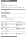
OM11 - EPI2 DeviceNet interface
Installation & Maintenance Instructions
KEYSTONE
Table of contents
1. Introduction
1Introduction
1
2
Operation and storage
1
3
Communication features
1
4
4.1
4.2
4.3
DeviceNet interface module
On board indication
Wiring diagram
Bus/hardwired mode selection
2
2
2
3
5
Brief DeviceNet description
5.1 Network cable
5.2Terminator
3
3
3
6
6.1
6.2
6.3
6.4
6.5
6.6
6.7
6.8
Communication interface
Actuator commands
Actuator status and indication
6.2.1 Positioning algorithm
Fail Safe data
Positioner configuration data
User defined data
Configuration data
DeviceNet configurable parameters
EDS file
4
4
4
6
6
6
6
6
7
7
7
7.1
7.2
7.3
Local Settings
On-boards interface
DeviceNet MACID setting
DeviceNet date rate setting 7
8
8
8
8
9
Bluetooth communication module
DeviceNet certificate
8
8
The OM11 DeviceNet interface is an electronic module that allows you to connect the Keystone EPI2
electrical actuator to a DeviceNet network. The module has its own microprocessor and acts as a
pure bus interface without affecting the actuator control integrity. It is installed inside the actuator
housing and takes the electrical power from the actuator power supply module. The DeviceNet
network is fully isolated from the actuator electronics. For details about EPI2 actuator the reference
manual is: EPI2 Quarter-turn Electric Actuator IOM.
Warning
EPI2 actuators must be electrically isolated before any disassembling or reassembling
operations. Before any disassembling or reassembling operations, please follow in detail the
relevant paragraph of the basic installation and operating manual (latest revision available).
Warning
The electronic parts of the EPI2 actuators and all option modules can be damaged by a
discharge of static electricity. Before you start, touch a grounded metal surface to discharge
any static electricity.
Warning
It is assumed that the installation, configuration, commissioning, maintenance and repair
works are carried out by qualified personnel and checked by responsible specialists.
Warning
Repair work, other than operations outlined in this manual, is strictly reserved to qualified
Pentair personnel or to personnel authorized by the company itself.
2. Operation and storage
The module is designed to work and to be stored in the same environment of the actuator.
3. Communication features
Communication protocol
CAN bus standard, 5 wires DeviceNet application
Network topology
Line / Trunk-drop topology
Transmission medium
Specific cable for DeviceNet network:1 twisted pair for power, 1 twisted pair for data and shield
Data rate 125
250
500
Kbps
Cable length 500
250
100
m
(length may vary also with cable thickness)
Device number
64 devices per segment
Bus access
Producer-consumer network
Bus termination
External bus terminators required
Keystone implementation
Device type
Group
Physical layer
Current consumption
Communication
Baud rate Addressing (MACID)
Temperature
EMC protections
www.pentair.com/valves
Generic (00hex)
Group 2 only slave
Isolated node with transceiver powered by the network
Current drawn from the network to power the transceiver: 29 mA at 24 V; 27 mA at 17 V; 25 mA at 11 V
Predefined master/slave connection: explicit message and polled I/O
125 Kbps, 250 Kbps, 500 Kbps (default 125 Kbps). Network configurable or manual configurable via on-board
rotary BCD switch
0-63 (default 63). Network configurable or manual configurable via on-board rotary BCD switches
-40°C, +85°C
EN 50081-2 and EN 50082-2
Pentair reserves the right to change the contents without notice
EBPRM-0101-EN-1307
OM11 - EPI2 DeviceNet interface
Installation & Maintenance Instructions
4. DeviceNet interface module
The module consists in a single PCB that is installed inside the actuator housing. It is connected
to the EPI2 base card via flat cable. The internal wiring connects the DeviceNet data lines to the
actuator terminal board.
Local configuration
interface
Network status LED:
NET_STAT
RESET push button
4.1 On-board indication module
The DeviceNet interface is equipped with 5 LEDs, pushbuttons and BCD rotary switches to offer a
configuration and diagnostic interface on-board.
MOD_STAT
Module Status LED as defined in spec. Vol. 3 ‘DeviceNet Adaptation for CIP’, chapter 9.
Condition
Description
LED
No power
Operational
Off
Green
Standby
Flashing green
Minor fault
Flashing red
Unrecoverable fault
Red
There is no power applied to the device
The device is operating in a normal
condition
The factory commissioning is not finished:
serial number not yet assigned
Recoverable fault due to a non critical
diagnostic indication
Device has an unrecoverable fault:
- HW alarm
- Power failure alarm
- Position sensor alarm
- High temperature alarm
NET_STAT
Network Status LED as defined in spec. Vol. 3 ‘DeviceNet Adaptation for CIP’, chapter 9.
Description
LED
Condition
Not powered/not on-line
On-line, not connected
Link OK on-line connected
Connection time-out
Critical link failure
Off
Flashing green
Green
Flashing red
Red
Communication faulted and
received anidentify comm
fault request – long protocol
Flashing red & green
Device is not on-line
Device is on-line, but is not allocate to a Master
Device is on-line and is not allocate to a Master
One ore more I/O connection are in timed-out state
Failed communication device. The device has
detected an error that has rendered it incapable of
communicating on the network (Duplicate MACID
or Bus-Off)
A specific Communication Faulted device
The device has detected a Network Access error
and is in the Communication Faulted state. The
device has subsequently received and accepted
an Identify Communication Faulted Request-Long
Protocol message
RESET
Reset pushbutton
Local configuration
On-board interface for local configuration of MACID and Baud Rate. By default the board is set to accept MACID and Baud Rate from the network, but it
is also possible to set these parameters by hardware setting. Detailed procedures are given in chapter 7: ‘Local configuration’
4.2 Wiring diagram
The Devicenet interface is connected to the actuator terminal board by internal wiring as shown below:
Optional module - DeviceNet interface
Connector H
5
6
HW Mode
7
8
9
CAN_V+
(red)
17
18
CAN_H
(white)
CAN_V(black)
19
Shield
CAN_L
(blue)
DeviceNet line
Pentair reserves the right to change the contents without notice
page 2
OM11 - EPI2 DeviceNet interface
Installation & Maintenance Instructions
4.3 Bus/hardwired mode selection
The DeviceNet interface manages the bus/hardwired mode selection by means of the input
terminal indicated with HW MODE. The physical input accepts from 24 to 125 V DC or AC, polarity
insensitive. When the input is left unconnected or no voltage is applied, the actuator is under bus
control from which is possible to send commands and read status.
When an appropriate voltage is applied to the HW MODE input, the actuator turns under
Hardwired control. In this condition the bus can only read actuator status while the actuator follows
the hardwired open and close controls connected to the terminal board. For further details see the
relevant wiring diagram and the user’s manual: EPI2 Quarter-turn Electric Actuator IOM.
5. Brief DeviceNet description
DeviceNet is a low-level network that provides connection between industrial field devices
(sensors and actuators) and higher-level devices (controllers). DeviceNet uses CAN (Controller Area
Network) for its datalink layer, and CIP (Common Industrial Protocol) for the upper layers of the
network. The major physical and media characteristics of the DeviceNet are:
• Trunk-line / drop-line topology of the network;
Trunk
TR
TR
Drop
• Support for up to 64 devices in a network (i.e. 1 master and 63 EPI2 actuators);
• Node removal without altering the network behavior;
• Support of both network-powered and self-powered devices on the same network;
• Wiring error protection;
• Selectable data rate of 125 k baud, 250 k baud and 500 k baud.
Drop length
Data rate
Trunk distance
Maximum
Cumulative
125 k baud
250 k baud
500 k baud
500 meters
250 meters
100 meters
6 meters
6 meters
6 meters
156 meters
78 meters
39 meters
• Adjustable power configuration to meet individual application needs;
• High current capability (up to 8 A at 24 V DC);
• Operation with off-the-shelf power supplies;
• Available power taps that allow the connection of several power suppliers;
• Build-in overload protection;
• Controller Area Network (CAN) technology for Media Access Control and Physical Signalling.
PLC
DeviceNet scanner
PowerTap
Term.
Tap
DeviceNet
Power supply
CAN V+
CAN H
Shield
CAN L
CAN V-
5.1 Network cable
To obtain the expected performances from the communication network the suitable cable must
be utilized. DeviceNet requires a specific cable composed of a Power pair, a Data Pair and a shield
with drain wire. DeviceNet defines different
cables to be used in the different parts of
the network:
• in the trunk line is normally used the
thick cable.
E.g. BELDEN 3082A:
1 pair 15 AWG 19x28 Tinned Copper –
Term.
Tap
Tap
Power pair
1 pair 18 AWG 19x30 Tinned Copper –
Data pair inner shield 100% coverage
• in the drop line is normally used the
thick cable. e.g. BELDEN 3084A
E.g. BELDEN 3084A:
1 pair 22 AWG 19x34 Tinned Copper –
Power pair
1 pair 24 AWG 19x36 Tinned Copper –
Data pair inner shield 100% coverage
5.2 Terminator
The DeviceNet network must be terminated to each end of the main trunk line with a 120 ohm
resistor across CAN_H and CAN_L data line.
Pentair reserves the right to change the contents without notice
page 3
OM11 - EPI2 DeviceNet interface
Installation & Maintenance Instructions
6. Communication interface
The following paragraph describes the input and output data available at the DeviceNet interface.
In all cases a parameter is called ‘input signal’ when data is sent from actuator to bus, vice-versa it
is called ‘output signal’ when data is sent from bus to slave.
6.1 Actuator commands
The commands are received from the DeviceNet network and are forwarded to the base card via the
internal data bus.
Output Assembly Instance: Class 4; Instance 101; Attribute 3
Byte
b7b6b5b4b3b2b1b0
0 ReservedReservedReservedReservedPositioner Stop
Close
Open
Enable
Command
Command
Command
1
ReservedReservedReservedReservedReservedReservedReservedReserved
2
LSB Set point
3
MSB Set point
Indication
Open Command
Close Command
Stop Command
Positioner Enable
Set point
Description
When this bit is set to 1 an Open Command is issued to the actuator.
The open command is maintained during the whole movement from the start of the bus
command until the Open Limit has been reached. The open command is reset when a
STOP Command is received from the bus.
When this bit is set to 1 a Close Command is issued to the actuator.
The close command is maintained during the whole movement from the start of the bus
command until the Close Limit has been reached. The close command is reset when a
Stop Command is received from the bus.
When this bit is set to 1 a Stop Command is issued to the actuator. A Stop Command
received from the bus resets both open and close commands.
When this bit is set to 1 the on-board positioner is enabled. The positioner is enabled
until this bit is set to 0.
The Setpoint received from the bus is used to produce the open or close commands to
the actuator as defined in paragraph 6.2.1: ‘Positioning algorithm’.
Data Type
Boolean
Range
0-1
E.U.
-
Boolean
0-1
-
Boolean
0-1
-
Boolean
0-1
-
Integer
0-1000
0.1%
6.2 Actuator status and indication
The status is received from the base card via the internal data bus and is reported to the DeviceNet network.
Input Assembly Instance: Class 4; Instance 100; Attribute 3
Byte
b7b6b5b4b3b2b1b0
0
PositionerIntermediate Motor
active
position
stopped
Fully
close
Actuator Closing Opening
moving
Fully
open
1
Monitor
Reserved
PDA
HW Mode
LOCAL
General
Not Oper
Not Oper
Relay Active
Active
selected
ALARM
Close
Open
2
HW alarm
Mid travel
alarm
Motor dir.
alarm
Opt. loc.
cnt. alarm
Strk. limit
alarm
Torque
CL alarm
Torque
OP alarm
Pwr fail
alarm
3 ReservedReservedReservedReservedReservedReservedHigh tempPos. Sen.
alarm
alarm
4
LSB Current Position
5
MSB Current Position
6 Current Torque
7
Current Temperature
Pentair reserves the right to change the contents without notice
page 4
OM11 - EPI2 DeviceNet interface
Installation & Maintenance Instructions
Indication
Fully Open
Opening
Closing
Actuator Moving
Fully Close
Motor Stopped
Intermediate position
Positioner active
Alarm in Open Direction
Alarm in Close Direction
General Alarm
LOCAL selected
HardWired Mode
selected
PDA Active
Monitor Relay
Power failure alarm
Torque alarm in opening
Torque alarm in closing
Stroke limit alarm
Local control alarm
Motor direction alarm
Jammed valve
HW alarm
Position sensor alarm
High temperature alarm
Current position
Current torque
Internal temperature
Description
The Fully Open indication is set to 1 when the actuator is at Fully Open position.
This indication reflects the status of the open limit on the actuator.
The Opening indication is set to 1 when the actuator is moving toward opening
direction.
The Closing indication is set to 1 when the actuator is moving toward closing
direction.
This indication is set to 1 when the actuator is moving either in opening or in
closing direction.
The Fully Close indication is set to 1 when the actuator is at Fully Close position.
This indication reflects the status of the close limit on the actuator.
This indication is set to 1 when the actuator is not moving and the motor has
stopped.
This indication is set to 1 when the valve is at an intermediate position.
This indication is set to 1 when the on-board positioner is enabled.
Open command not available due to current alarm trip in open direction. The
diagnostic indication is cleared when the alarm that has generated the fault
disappears.
Close command not available due to current alarm trip in close direction. The
diagnostic indication is cleared when the alarm that has generated the fault
disappears.
Bus can only read data due to alarm present. The diagnostic indication is cleared
when all the alarm conditions are cleared.
No operation from bus because LOCAL selector switch is activated. The
diagnostic indication is cleared when the selector is turned to REMOTE.
No operation from bus because HARDWIRED mode is activated. The diagnostic
indication is cleared when the input HW MODE is not powered.
No operation from bus because PDA operator interface has the control (only if
Bluetooth option is available). The diagnostic indication is cleared when the PDA
control is released.
This indication is set to 1 when the actuator is available for bus control. Monitor
Relay indication means that the local selector is at Remote position, no other
remote interfaces have the control (Hardwired or PDA) and no alarms are present.
This bit is set when the main power supply is not in the proper range. The
diagnostic indication is cleared at the next power up if the power supply is
corrected.
This bit is set when the Torque has reached the programmed limit while the
actuator was moving in opening direction. The diagnostic indication is cleared by
a Close command
This bit is set when the Torque has reached the programmed limit while the
actuator was moving in closing direction. The diagnostic indication is cleared by
an Open command.
This bit is set when the current position is behind the Open or Close limit
switches or as result of an incorrect Torque Set. The diagnostic indication is
cleared when the position returns within the limits or after a successful Torque
Set procedure
This bit is set when the optional Local Control Module does not work correctly.
The diagnostic indication is cleared when the Local Control works without
problems.
This bit is set when the motor drive has recognised an incorrect behaviour. The
diagnostic indication is cleared by a command in the opposite direction.
This bit is set when the actuator detects a jammed valve condition. The
diagnostic indication is cleared by any new command.
This bit is set when the actuator detects a general hardware error. The diagnostic
indication is cleared at the next power up under normal condition.
This bit is set when the actuator detects that position sensor is not working
properly.
This bit is set when the internal temperature is out of the operational limits. The
diagnostic indication is cleared when the internal is within the limits.
The current position read from base card
The current torque read from base card
The current internal temperature
Data Type
Boolean
Range
0-1
E.U.
-
Boolean
0-1
-
Boolean
0-1
-
Boolean
0-1
-
Boolean
0-1
-
Boolean
0-1
-
Boolean
Boolean
Boolean
0-1
0-1
0-1
-
Boolean
0-1
-
Boolean
0-1
-
Boolean
0-1
-
Boolean
0-1
-
Boolean
0-1
-
Boolean
0-1
-
Boolean
0-1
-
Boolean
0-1
-
Boolean
0-1
-
Boolean
0-1
-
Boolean
0-1
-
Boolean
0-1
-
Boolean
0-1
-
Boolean
0-1
-
Boolean
0-1
-
Boolean
0-1
-
Integer
Integer
Integer
0-1000
0-100
-45 +85
0,1%
%
°C
Pentair reserves the right to change the contents without notice
page 5
OM11 - EPI2 DeviceNet interface
Installation & Maintenance Instructions
6.2.1 Positioning algorithm
A positioning algorithm (position closed loop control) is implemented on the DeviceNet interface
module.
The positioning function consists of comparing the position, received from the base card, with the
position request received from bus. If the difference between ‘position request and present position’
is greater than ‘Dead Band’ an Open or a Close command is send to base card. The dead Band is
configurable via bus from 0.3 to 2.0%.
6.3 Fail Safe data
The Fail Safe data parameter defines the behavior of the actuator in case of network communication failure. The Fail Safe data parameter can be
modified via DeviceNet network.
Indication
Description
Parameter 1: Class 100; Instance 1; Attribute 100
Safety action
The action to execute in case of loss of bus communication.
0= No action
1= Stop
2= Close
3= Open
4= Go to predefined position
Parameter 2: Class 100; Instance 1; Attribute 101
Predef. safety position Safe predefined position
Parameter 3: Class 100; Instance 1; Attribute 102
Delay on bus fail
Delay before to initiate the Safety Action
Direction
Data Type Range
Default
E.U.
R/W
Integer
0-4
0
-
R/W
Integer
0-100
50
%
R/W
Integer
0-10
4
sec
6.4 Dead Band configuration
The Dead Band indicates the maximum allowed deviation from the valve position and the requested position. If the deviation is bigger, an open or close
control command will be generated.
Indication
Description
Parameter 4: Class 100; Instance 1; Attribute 103
Dead Band
This parameter defines the Dead Band of the positioning function available on the modulating actuator (in tenth of %).
The movement is inhibited until the difference between current
position and requested position (position error) is lower
than Dead Band.
Direction
Data Type Range
Default
E.U.
R/W
Integer
15
0.1%
Default
E.U.
3- 20
6.5 User defined data
The User defined data is stored in the EPI2 actuator and is available on the DeviceNet network for Asset Management information.
Indication
Description
Parameter 5: Class 100; Instance 1; Attribute 104
Actuator serial number Actuator serial number
Parameter 6: Class 100; Instance 1; Attribute 105
Actuator type
Actuator type Parameter 7: Class 100; Instance 1; Attribute 106
Valve tag Valve tag
Direction
Data Type Range
Only read
Short string 12 bytes -
-
Only read Short string 12 bytes -
-
Only read
Short string 12 bytes -
-
6.6 Configuration data
The Configuration data is received from the base card via the internal data bus and is reported to the DeviceNet network. The Configuration data can
also be modified via the DeviceNet network and the interface will send the new values to the logic board.
Indication
Description
Parameter 8: Class 100; Instance 1; Attribute 112
Close direction
The direction the actuator drives the motor when it receives a Close command.
0= Clockwise (CW)
1= Clockwise (CCW)
Parameter 9: Class 100; Instance 1; Attribute 113
Opening speed set
It defines the speed of the motor when opening.
Parameter 10: Class 100; Instance 1; Attribute 114
Closing speed set
It defines the speed of the motor when closing.
Parameter 11: Class 100; Instance 1; Attribute 115
Opening torque set
Opening torque.
Parameter 12: Class 100; Instance 1; Attribute 116
Closing torque set
Closing torque.
Pentair reserves the right to change the contents without notice
Direction
Data Type Range
Default
E.U.
R/W
Integer
0-1
1
-
R/W
Integer
0-9
7
-
R/W
Integer
0-9
7
-
R/W
Integer
0-9
7
-
R/W
Integer
0-9
7
-
page 6
OM11 - EPI2 DeviceNet interface
Installation & Maintenance Instructions
Indication
Description
Parameter 13: Class 100; Instance 1; Attribute 117
Open limit
It defines the end of travel setting in Open direction: 0= open limit by torque
1= open limit by position
Parameter 14: Class 100; Instance 1; Attribute 118
Close limit
It defines the end of travel setting in Close direction:
0= close limit by torque
1= close limit by position
Parameter 15: Class 100; Instance 1; Attribute 119
Nominal torque
Nominal torque of the motor:
0= 63 Nm
1= 125 Nm
2= 250 Nm
3= 500 Nm
4= 1000 Nm
5= 2000 Nm
Parameter 16: Class 100; Instance 1; Attribute 120
LED colour code
It defines the colour of the LED indicating the Fully Open and Fully Close position:
0: Open: LED=green;
Close: LED=red
1: Open: LED= red;
Close: LED= green
Direction
Data Type Range
Default
E.U.
R/W
Integer
0-1
1
-
R/W
Integer
0-1
1
-
Only read
Integer
0-5
-
-
R/W
Integer
0-1
0
-
6.7 DeviceNet configurable parameters
For correct communication and identification of the actuator it is required to configure the correct MACID and Baud Rate.
Indication
Description
Parameter 17: Class 3; Instance 1; Attribute 1
MACID
The MACID to assign to the device
Parameter 18: Class 3; Instance 1; Attribute 2
Baud Rate
The Baud Rate to assign to the device
Direction
Data Type Range
Default
E.U.
R/W
Unsigned
0-63
63
-
R/W
Unsigned
0-2
0
-
6.8 EDS file
The DeviceNet interface module is provided with an Electronic Data Sheet (EDS) file. The EDS file
is DeviceNet specific and provides information about the device configuration data. The EDS file is
used by the DeviceNet configuration tool in order to get all the information necessary to the device
configuration and to the access and alter the configurable parameters of the EPI2 actuator.
7. Local settings
The DeviceNet interface module is equipped with 3 on-board selector switches to allow the
operator configuration of both the MACID and the Baud Rate of DeviceNet communication.
To access the on-board interface on the DeviceNet interface module it is necessary to follow the
procedures explained in ‘EPI2 Quarter-turn Electric Actuator IOM’ at Chapter 6: ‘Actuator settings
and configuration’ and then follow the procedures described in the next paragraphs.
7.1 On-boards interface
The on-board interface is equipped with the following switches and indications.
MSB-LSB Address
BCD Rotary switches
DATA_RATE
BCD Rotary switch
CNF_OK LED
ENTER pushbutton
ON_CFG LED
ENA_CFG switch
Pentair reserves the right to change the contents without notice
page 7
OM11 - EPI2 DeviceNet interface
Installation & Maintenance Instructions
7.2 DeviceNet MACID configuration
The DeviceNet interface module allows MACID setting both for manual configuration as for software
configuration by means of two ten-position BCD rotary switches as indicated in the figure.
The current setting is read in decimal representation:
MSB_ADD specifies the ten (1x, 2x, 3x, …); LSB_ADD specifies the unit (x1, x2, x3, …).
Manual configuration
When BCD rotary switches specify a valid DeviceNet MACID, i.e. a value from 00 to 63, the module
considers this value as the device MACID.
Software configuration
If the switches specify an invalid DeviceNet MACID, i.e. a value greater than 63, the module uses the
value stored in non-volatile memory and is ready for software configuration of MACID via specific
communication message.
MACID configuration
Configuration procedure
To change the current value of the BCD rotary switches to set a different MACID, the user shall
follow this procedure:
• Move the dip switch ENA_CFG to the ON position: the ON_CFG LED is activated to indicate that
the actuator has entered Configuration Mode
• Set the new MACID via the rotary switches MSB_ADD and LSB_ADD.
E.g.: to set MACID = 28:
MSB_ADD. on position 2
LSB_ADD on position 8
• Press the pushbutton ENTER to confirm the new set: if the new MACID is correct the CFG_OK
LED turns ON
• Move the dip switch ENA_CFG on the OFF position to exit from Configuration Mode: the
DeviceNet interface module is reset to activate the new configuration.
Communication speed configuration
7.3 DeviceNet communication speed configuration
The DeviceNet interface module allows also Date Rate setting via manual configuration (or software
configuration) by means of one ten-position BCD rotary switch DATA_RATE as indicated in the
figure.
Manual configuration
When BCD rotary switch specify one of the following valid DeviceNet Data Rate:
0: 125 Kbps
1: 250 Kbps
2: 500 Kbps
the module will work at the selected data rate.
Software configuration
If the switches specify any other invalid DeviceNet Data Rate, i.e. a value from 4 to 9, the module
uses the value stored in non-volatile memory and is ready for software configuration of Data Rate
via a specific communication message.
Configuration procedure
To change the current value of the BCD rotary switch to set a different Data Rate, the user shall
follow this procedure:
• Move the dip switch ENA_CFG on the ON position: the ON_CFG LED turns ON to indicate that
the actuator is entered in Configuration Mode
• Set the new Data Rate on the rotary switches DATA_.
• Press the pushbutton ENTER to confirm the new set: if the new MACID is correct the CFG_OK
LED turns ON
• Move the dip switch ENA_CFG on the OFF position to exit from Configuration Mode: the
DeviceNet interface module is reset to activate the new setting.
8. Bluetooth communication module
The OM11 module is provided with integrated Bluetooth module. In www.biffi.it you can download
A-Manager program to modify each settings by integrated Bluetooth module. After installation of
A-Manager program, please clic on ‘Operations’button and then clic on ‘Bluetooth Control’button
and tick ‘on’.
The features and functionalities performed with Bluetooth module are indicated in A-Manager IOM
for PDA (BIFCS-0029) and PC (BIFCS-0028).
9. DeviceNet certificate
EPI2 actuators family equipped with DeviceNet interface module have passed the DeviceNet
Conformance Test and can be declared.
DeviceNet CONFORMANCE TESTED™
Copy of the DeviceNet certificate can be viewed at ODVA website: www.odva.org
Pentair reserves the right to change the contents without notice
page 8