1
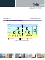
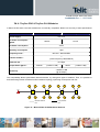
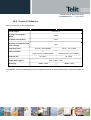
M-ONE Protocol Stack User Guide 1vv0300819 Rev.1 – 15/07/2009 M-ONE Protocol Stack User Guide 1vv0300819 Rev.1 – 15/07/2009 This document is related to the following products : Reproduction forbidden without Telit Communications S.p.A. written authorization - All Rights Reserved page 1 of 53 M-ONE Protocol Stack User Guide 1vv0300819 Rev.1 – 15/07/2009 DISCLAIMER The information contained in this document is the proprietary information of Telit Communications S.p.A. and its affiliates (“TELIT”). The contents are confidential and any disclosure to persons other than the officers, employees, agents or subcontractors of the owner or licensee of this document, without the prior written consent of Telit, is strictly prohibited. Telit makes every effort to ensure the quality of the information it makes available. Notwithstanding the foregoing, Telit does not make any warranty as to the information contained herein, and does not accept any liability for any injury, loss or damage of any kind incurred by use of or reliance upon the information. Telit disclaims any and all responsibility for the application of the devices characterized in this document, and notes that the application of the device must comply with the safety standards of the applicable country, and where applicable, with the relevant wiring rules. Telit reserves the right to make modifications, additions and deletions to this document due to typographical errors, inaccurate information, or improvements to programs and/or equipment at any time and without notice. Such changes will, nevertheless be incorporated into new editions of this document. Copyright: Transmittal, reproduction, dissemination and/or editing of this document as well as utilization of its contents and communication thereof to others without express authorization are prohibited. Offenders will be held liable for payment of damages. All rights are reserved. © Copyright Telit RF Technologies 2009. Reproduction forbidden without Telit Communications S.p.A. written authorization - All Rights Reserved page 2 of 53 M-ONE Protocol Stack User Guide 1vv0300819 Rev.1 – 15/07/2009 CONTENTS CHAPTER I. INTRODUCTION .....................................................................................................................................4 I.1. AIM OF THE DOCUMENT .................................................................................................................................................................................... 4 I.2. REFERENCE DOCUMENTS ................................................................................................................................................................................. 5 I.3. DOCUMENT CHANGE LOG ................................................................................................................................................................................. 5 I.4. GLOSSARY ...................................................................................................................................................................................................... 6 CHAPTER II. GENERAL DESCRIPTION.....................................................................................................................7 II.1. DEFINITION AND SCOPE OF MESH NETWORKING .............................................................................................................................................. 7 II.2. TARGET OF TELIT MESH LITE .......................................................................................................................................................................... 9 II.3. BASIC PRINCIPLES ........................................................................................................................................................................................ 10 CHAPTER III. FUNCTIONALITIES.............................................................................................................................13 III.1. TYPICAL NETWORK ARCHITECTURE ............................................................................................................................................................. 13 III.2. DEVICE IDENTIFICATION .............................................................................................................................................................................. 14 III.3. TIME UTILIZATION ....................................................................................................................................................................................... 14 III.4. BEACON INFORMATION ................................................................................................................................................................................ 14 III.5. SUPER FRAME SCHEDULE ........................................................................................................................................................................... 15 III.6. ROUTING RULES ......................................................................................................................................................................................... 15 III.7. NETWORK CAPABILITIES .............................................................................................................................................................................. 16 III.8. AUTO ASSOCIATION AND AUTO REPAIR........................................................................................................................................................ 17 III.9. LOW POWER ............................................................................................................................................................................................... 17 CHAPTER IV. HARDWARE CONSIDERATION ........................................................................................................18 IV.1. TINYONE PRO & TINYONE PLUS MODULES ................................................................................................................................................ 19 IV.2. TINYONE LITE MODULES ............................................................................................................................................................................ 20 IV.3. HARDWARE DESCRIPTION ............................................................................................................................................................................ 21 CHAPTER V. DETAILED FUNCTIONING .................................................................................................................26 V.1. REGISTERS DESCRIPTION ............................................................................................................................................................................. 26 V.2. ADVANCED USE............................................................................................................................................................................................. 34 V.3. NETWORK BUILDING ...................................................................................................................................................................................... 42 V.4. FLASHING ..................................................................................................................................................................................................... 45 V.5. LOW POWER MODE........................................................................................................................................................................................ 46 CHAPTER VI. APPLICATION ....................................................................................................................................48 VI.1. TIMING CALCULATION FOR TINYONE PRO/PLUS MODULES........................................................................................................................... 48 VI.2. EXAMPLE OF APPLICATION ........................................................................................................................................................................... 50 Reproduction forbidden without Telit Communications S.p.A. written authorization - All Rights Reserved page 3 of 53 M-ONE Protocol Stack User Guide 1vv0300819 Rev.1 – 15/07/2009 CHAPTER I. INTRODUCTION I.1. Aim of the Document The aim of this document is to present the features and the application of the Mesh Lite embedded firmware (M-ONE) available on the TinyOne family. It is applicable for: -TinyOne Lite 433MHz -TinyOne Lite 868MHz (module and USB dongle) -TinyOne Plus 868MHz (module, USB dongle and terminal) -TinyOne Pro 868MHz (module and terminal) After the introduction, the characteristics of the Mesh Lite will be described within the following distinct chapters: - - general description, functionalities, hardware consideration, detailed functioning, examples of application. Reproduction forbidden without Telit Communications S.p.A. written authorization - All Rights Reserved page 4 of 53 M-ONE Protocol Stack User Guide 1vv0300819 Rev.1 – 15/07/2009 I.2. Reference documents ETSI Standards for SRD , Sept 2000 [1] EN 300 220-1 v1.3.1 ERC Recommendation for SRD, March 2001 [2] ERC Rec 70-03 [3] Mesh Manager User Guide 1vv0300823 [4] TinyTools User Guide 1vv0300824 I.3. Document change log Revision Date ISSUE # 0 17/04/09 ISSUE # 1 15/07/09 Changes First Release Update in Hayes commands and registers description Alignment of modules consumption Reproduction forbidden without Telit Communications S.p.A. written authorization - All Rights Reserved page 5 of 53 M-ONE Protocol Stack User Guide 1vv0300819 Rev.1 – 15/07/2009 I.4. Glossary ACP BER Bits/s CER dBm DOTA EMC EPROM ETR ETSI FM FSK GFSK GMSK IF ISM kbps LNA LSB MHz µC ms MSB PLL PROM NRZ RF RoHS RSSI Rx SRD Tx SMD VCO VCTCXO Adjacent Channel Power Bit Error Rate Bits per second (1000 bits/s = 1Kbps) Character Error Rate Power level in decibel milliwatt (10 log (P/1mW)) Download Over The Air Electro Magnetic Compatibility Electrical Programmable Read Only Memory ETSI Technical Report European Telecommunication Standard Institute Frequency Modulation Audio Frequency Shift Keying Gaussian Frequency Shift Keying Gaussian Minimum Shift Keying Intermediary Frequency Industrial, Scientific and Medical kilobits/s Low Noise Amplifier Least Significant Byte Mega Hertz (1 MHz = 1000 kHz) Micro Controller Millisecond Most Significant Byte Phase Lock Loop Programmable Read Only Memory Non return to Zero Radio Frequency Restriction of Hazardous Substances Receive Strength Signal Indicator Reception Short Range Device Transmission Surface Mounted Device Voltage Controlled Oscillator Voltage Controlled and Temperature Compensated Crystal Oscillator Reproduction forbidden without Telit Communications S.p.A. written authorization - All Rights Reserved page 6 of 53 M-ONE Protocol Stack User Guide 1vv0300819 Rev.1 – 15/07/2009 CHAPTER II. GENERAL DESCRIPTION II.1. Definition and Scope of Mesh Networking A wireless mesh network topology stands for a multihop network where nodes can send and receive messages, and also function as a router to relay messages for its neighbors. Through the relaying process, a packet of wireless data will find its way to its destination, passing through intermediate nodes with reliable communication links. Figure 1 - Example of mesh topology Reproduction forbidden without Telit Communications S.p.A. written authorization - All Rights Reserved page 7 of 53 M-ONE Protocol Stack User Guide 1vv0300819 Rev.1 – 15/07/2009 Ö Mesh networking is the ability to use a wireless device as logical repeater to transfer data between two end points without direct radio connection. It is a way to increase reliability and distance of a wireless link. There are two types of mesh topology, full mesh and partial mesh : • Full mesh topology occurs when every node has a connection to every other node in the network. Full mesh is very expensive to implement but yields the greatest amount of redundancy, so in the event that one of those nodes fails, network traffic can be directed to any of the other nodes. Full mesh is usually reserved for backbone networks. Figure 2 - Full mesh topology • Partial mesh topology is less expensive to implement and yields less redundancy than full mesh topology. With partial mesh, some nodes are organized in a full mesh scheme but others are only connected to one or two in the network. Partial mesh topology is commonly found in peripheral networks connected to a full meshed backbone. Figure 3 - Partial mesh topology Reproduction forbidden without Telit Communications S.p.A. written authorization - All Rights Reserved page 8 of 53 M-ONE Protocol Stack User Guide 1vv0300819 Rev.1 – 15/07/2009 II.2. Target of Telit Mesh Lite The target of Mesh Lite is to fit the common customer applications, while keeping simplicity and cost efficiency. Mesh Lite is available on new TinyOne family products, allowing upgrade of the standard firmware of existing application without any new design. Here are the key characteristics of Mesh Lite : • Most of the applications targeted is gathering in information from a central point or controlling devices from a central point. Therefore, a partial mesh is sufficient and cluster tree topology is a natural choice which matches most of the applications. Ö Mesh Lite is a partial mesh network based on Cluster Tree topology • A lot of applications targeted need efficient power management to be battery operated, so that all the network nodes must be low power. It implies a real management of stand-by mode for all the devices, even the routers. Ö Mesh Lite network is a true low power network • Furthermore, according to ETSI standards, 868 MHz radio modules have limited baud rate: any dynamic routing protocol would take significant part of the global bandwidth, and would impact bandwidth available for user data. Routing by the natural hierarchical addressing keep the maximum bandwidth for the user application while ensure high reliability. The destination is directly read from the network address of the sending and receiving device. Ö Mesh Lite network is based on hierarchical addressing • To keep maximum efficiency and simplicity in the use of Mesh Lite, it is important to implement an easy method for network building. It is done by auto acquisition capabilities, which means that each new device can automatically join the network if the ID parameters match. Ö Mesh Lite network has auto acquisition capability • Although Mesh Lite is a STATIC network topology (i.e. nodes can’t move dynamically in the network), the Mesh Lite has auto repair capabilities. If a link is lost for any reason, Mesh Lite detects this trouble and tries others associations to reach normal data transmission. Ö Mesh Lite network is static but with auto repair capability Reproduction forbidden without Telit Communications S.p.A. written authorization - All Rights Reserved page 9 of 53 M-ONE Protocol Stack User Guide 1vv0300819 Rev.1 – 15/07/2009 II.3. Basic principles Network set up The network can be either set up manually according to user preferences or almost automatic for easier and faster configuration. There are 3 different logical devices : • The Coordinator is at the top of the tree (Layer 0), it is only able to exchange data with device placed under. • Routers are present at each middle layers and can exchange data either with upper or lower devices. A Router can be the final recipient of a frame, or can route a frame to another layer. • EndPoints are placed at each termination of the tree; they can only exchange data with the upper layer. The setting up of the network can be dynamic : • Once the network master is up and running, any new device coming up in a reachable distance will attach itself to the root if the network ID and optional security parameters match. • The same process applies for depth N node becoming root for depth N+1 Communication Master – leaf communication This is the typical use of this functionality, devices are addressed by a unique identifier (serial number), and they dynamically acquire their network address. Since this address is based on a hierarchical structure, the data flow follows the tree structure (see Figure 4). Network Master Communication path Figure 4 – Master to Leaf Communication Reproduction forbidden without Telit Communications S.p.A. written authorization - All Rights Reserved page 10 of 53 M-ONE Protocol Stack User Guide 1vv0300819 Rev.1 – 15/07/2009 Leaf- Leaf Communication This is also supported, but should keep in mind that whole traffic goes through the nearest common root node between the two leaves therefore, it is limited to low traffic type applications. Network Master Communication path Figure 5 – Leaf to Leaf Communication Reproduction forbidden without Telit Communications S.p.A. written authorization - All Rights Reserved page 11 of 53 M-ONE Protocol Stack User Guide 1vv0300819 Rev.1 – 15/07/2009 Maintenance The maintenance of the network is dynamic : • Master node failure : it is a critical failure which requires this node to be replaced for the network to function again. Then the whole network sets back automatically. • Router node failure : all the devices attached to this node reinitialize their network attachment procedure in a transparent way and find another attachment point inside the network. Network Master Failing link New reliable link Figure 6 – Auto-repaired Logical Configuration Reproduction forbidden without Telit Communications S.p.A. written authorization - All Rights Reserved page 12 of 53 M-ONE Protocol Stack User Guide 1vv0300819 Rev.1 – 15/07/2009 CHAPTER III. FUNCTIONALITIES III.1. Typical Network Architecture Downward messages Layer 1 Layer 2 Upward messages Layer 0 Layer 3 Coordinator Router EndPoint Figure 7 - Symbolic tree Organization. Reproduction forbidden without Telit Communications S.p.A. written authorization - All Rights Reserved page 13 of 53 M-ONE Protocol Stack User Guide 1vv0300819 Rev.1 – 15/07/2009 III.2. Device Identification Each device has a stable identifier, it is a 2 bytes device_ID, chosen and entered by the customer when setting its parameters. III.3. Time Utilization The timing used in our Mesh Lite is inspired from ZigBeeTM : it uses beacon and super frame. Because of the slowness of our 868MHz devices (carrier duration, Rx to Tx switching time…), the CSMACA is not systematically used like in ZigBeeTM. This will be detailed in the ‘Super frame schedule’ paragraph. Each device has to wake up and listen the beacon issued from the upper device; this beacon is waited at a known moment. At this time, start the super frame during which the most exchanges have to be done. At the end of the max super frame duration, the device must enter in sleeping mode. If there are uncompleted exchanges, they are planned for the next beacon. If no exchange is pending for the device at the start of the super frame, it can enter in sleeping mode without waiting the max super frame duration. The super frame duration and the time between beacons are settings chosen at the installation and available for the entire network. Beacon Super Frame Obligatory sleeping time t Figure 8 - Time repartition. III.4. Beacon information The Beacon is sent periodically by an upper device to all lower devices directly associated to it. The first information carried by the Beacon is the time synchronization. To not miss the beginning of the beacon, lower devices have to wake up a short time before. As the beacon begins, the lower devices synchronize their timers. The beacon contains network information like Network ID, Super frame max duration, time between beacons etc. It also contains the upper device association capabilities and its deep from coordinator. The network capabilities is the number of new devices could still join the Router. More details will be done in the next parts. Finally, the beacon gives the list of recipients for which a downward message is pending. Reproduction forbidden without Telit Communications S.p.A. written authorization - All Rights Reserved page 14 of 53 M-ONE Protocol Stack User Guide 1vv0300819 Rev.1 – 15/07/2009 III.5. Super Frame schedule Super frame time is divided in two parts : the first one is assigned for downward messages while the other one is for upward messages. The duration of the first part could be null if no downward message is pending. By opposition, it can’t exceed half of the max super frame duration to allow upward message treatment. The downward messages are treated one by one following the list order given in the beacon; each lower device must wait its turn to download their messages. During the second part, lower devices can upload their messages using CSMACA. In order to save time, each transmission is always acknowledged immediately using neither CSMACA nor Device_ID. This would not decrease the reliability since the time between transmission and ACK is well known, and since the others devices are listening at least the Rx/Tx switching time before considering a channel is free. III.6. Routing rules A Router which has initiated a beacon is the master during the beginning Super Frame. Each Router has in its memory the list of all Device_ID present under it (children list). When a router receives an upward message with valid CRC, it always acknowledges it and checks the recipient ID : • If the recipient ID matches its own ID, it treats the frame for himself. • Else, if the recipient ID matches one of the children list, the frame is buffered to be sent downstream later. • Else, the frame is buffered to be sent upstream later. When a router receives a downward message with valid CRC, it first checks the recipient ID : • If the recipient ID matches its own ID, it acknowledges the message and treats the frame for himself. • Else, if the recipient ID matches one of the children list, it acknowledges the message and the frame is buffered to be sent downstream later. • Else, the frame is ignored and no acknowledge is performed. Reproduction forbidden without Telit Communications S.p.A. written authorization - All Rights Reserved page 15 of 53 M-ONE Protocol Stack User Guide 1vv0300819 Rev.1 – 15/07/2009 III.7. Network capabilities Direct children ≤ 100 The coordinator doesn’t need to have a children list because it is at the top layer. The only limit is fixed by the two byte ID assignation. It is possible to have a coordinator surrounded by 10.000 EndPoints. Total children ≤100 For Routers, the limit of children list size is 200 bytes so each router can support 100 children (direct or not). A possible direct children number limitation is to be defined. Figure 9 - Children limitation Due to timing precision necessity, there is also a limitation in the depth of the network. There can not be a link with more than 15 hops into the network. Number of hops ≤ 15 Figure 10 - Depth limitation To conclude on network capabilities, the limitations are: • Not exceeding a total number of 10.000 devices into the network. • Not exceeding a total number of 100 children per router. • The depth limitation of the network is 15. Those singles limitations allow imagining a lot of various networks from Rangy to Bushy type. Reproduction forbidden without Telit Communications S.p.A. written authorization - All Rights Reserved page 16 of 53 M-ONE Protocol Stack User Guide 1vv0300819 Rev.1 – 15/07/2009 III.8. Auto Association and Auto Repair As been said above, the Beacon contains the association capabilities and network depth of the Router. When a new device joins the network for the first time, it listens to all beacons and chooses the best Router. A ‘good’ Router is a device placed in a high layer, with a good RSSI level and which can still accept new children. When the new device has selected its Router, its sends a frame to join it. Then, the router adds the new device to its children list. In case of broken node, the top Router of the orphan sub network doesn’t inform its children in a first time, it attempts to join a new Router which can accept the total number of devices. In case of success, the list of all sub network devices is given to the new Router reached. If it’s impossible to find a Router with enough free space, the top Router of the orphan sub network informs its children to join another router by themselves. Router with 27 free places. Router with 5 free places. Link possible without any modification of the orphan sub Link possible only if the orphan sub network is burst Orphan sub network Figure 11 - Auto Repair III.9. Low power We have seen that at the end of the super frame, devices have to enter in sleeping mode. Power can be dramatically saved by setting a very long time between beacons but, of course, the final time to transmit a message through the entire network could take several minutes. By opposition, the speed can be enhanced by increasing the frequency of beacons. Obviously, Routers are the devices which need the more amount of power because they should wake up twice, one time to receive the upper layer beacon and one to send a beacon to the downer level. EndPoints can be very low power if the application can accept to wake up only once every n Beacons. Reproduction forbidden without Telit Communications S.p.A. written authorization - All Rights Reserved page 17 of 53 M-ONE Protocol Stack User Guide 1vv0300819 Rev.1 – 15/07/2009 CHAPTER IV. HARDWARE CONSIDERATION As specified earlier, the Mesh Lite embedded firmware is available on TinyOne family. It is applicable for : - TinyOne Lite 433MHz TinyOne Lite 868MHz (module and USB dongle) TinyOne Plus 868MHz (module, USB dongle and terminal) TinyOne Pro 868MHz (module and terminal) Reproduction forbidden without Telit Communications S.p.A. written authorization - All Rights Reserved page 18 of 53 M-ONE Protocol Stack User Guide 1vv0300819 Rev.1 – 15/07/2009 IV.1. TinyOne PRO & TinyOne PLUS Modules In Mesh Lite firmware, both radio modules are “functionally compatible”. Below is a summary of their specifications : Characteristics B868-tinyPRO B868-tinyPLUS 3 to 3.6 V Power Supply Tx Power consumption @3.6V 600mA 80 mA Rx Power consumption 30mA Stand-by consumption 10µA Frequency band : 869.400 – 869.650 MHz Channel number : 1 (center frequency 869.525MHz) 38.4 kbps Radio bit rate : 500mW Output Power @3.6V : (27dBm ± 1dB) 25mW (14dBm± 1dB) -100dBm ± 2dB (@ 38.4kbps) Sensitivity This compatibility allows hybrid Mesh network structure, by mixing both types of modules. Then, it is possible to build interesting network architectures like backbone topology, optimizing consumption and cost. PLUS PLUS PLUS PLUS PLUS PLUS PLUS PLUS PRO PRO PLUS PRO PLUS PLUS Medium distance link PRO PLUS PLUS PRO PLUS PLUS PLUS Long distance link Figure 12 – Mixed PRO & PLUS Backbone Network Reproduction forbidden without Telit Communications S.p.A. written authorization - All Rights Reserved page 19 of 53 M-ONE Protocol Stack User Guide 1vv0300819 Rev.1 – 15/07/2009 IV.2. TinyOne LITE Modules Below is a summary of their specifications : Characteristics B868-tinyLITE B433-tinyLITE 2.2 to 3.6 V Power Supply Tx Power consumption @3.6V 40mA Rx Power consumption 30mA Stand-by consumption (with clock running) 10µA Frequency band : 869.700 – 870.000MHz 433.05 – 434.79 MHz Channel number : 1 (center frequency 869.850MHz) 1 (center frequency 434.100MHz) 38.4 kbps 38.4 kbps Radio bit rate : 5mW (7dBm ± 1dB) Output Power @3.6V : Sensitivity -98dBm ± 2dB -98dBm ± 2dB The 868MHz module is available either with an integrated antenna or without antenna (RF connection through pin 1). Reproduction forbidden without Telit Communications S.p.A. written authorization - All Rights Reserved page 20 of 53 M-ONE Protocol Stack User Guide 1vv0300819 Rev.1 – 15/07/2009 IV.3. Hardware Description Considering hardware, all the modules are completely pin-to-pin compatible. Views of the module : TinyOne PRO & PLUS J24 J9 J25 J8 J32 J1 Top view of the radio module (with components upside) J9 J24 J8 J25 J1 J32 Bottom view of the radio module (with metallic cover upside) Reproduction forbidden without Telit Communications S.p.A. written authorization - All Rights Reserved page 21 of 53 M-ONE Protocol Stack User Guide 1vv0300819 Rev.1 – 15/07/2009 Views of the module : TinyOne LITE J24 J9 A N T E N N A J25 J8 J32 J1 Top view of the radio module (with antenna upside for 868MHz module) J9 J8 J24 J25 C O V E R RADIO PART DIGITAL PART J1 J32 Bottom view of the radio module (with metallic cover upside) Reproduction forbidden without Telit Communications S.p.A. written authorization - All Rights Reserved page 22 of 53 M-ONE Protocol Stack User Guide 1vv0300819 Rev.1 – 15/07/2009 Pin-out This list below must be taken as a reference for Mesh Lite firmware. Some signals are renamed compared to the module with standard firmware (for more details refer to the module/terminal user guides) due to enhanced functionalities. Interface function Pin I/O Signal level Function J32 I/O6 I/O TTL Digital I/O, interrupt Input capable. Refer to §V.2 for detailed use. (not connected if not used) J31 I/O5 I/O TTL Digital I/O, interrupt Input capable. Refer to §V.2 for detailed use. (not connected if not used) J30 WAKEUP I TTL Signal to wake-up the module in low power mode. Refer to §V.5 for detailed use. (not connected if not used) J29 TXD O TTL TxD UART – Serial Data Transmission. J28 RXD I TTL RxD UART – Serial Data Reception. J27 RESET I TTL Signal for resetting the module. J26 - - - J25 RTS O TTL J24 - - - Not connected. J23 VDD - - Digital part supply. J22 I/O4 I/O analog Digital I/O, Analog Input (10 bits) capable. Refer to §V.2 for detailed use. (not connected if not used) J21 I/O3 I/O analog Digital I/O, Analog Input (10 bits) capable. Refer to §V.2 for detailed use. (not connected if not used) J20 ASSO O TTL Signal indicating association status. Refer to §V.2 for detailed use. (not connected if not used) J19 STAND BY STATUS O TTL Signal indicating stand by status. Refer to §V.5 for detailed use. (not connected if not used) Not connected Request To Send. (not connected if not used) Reproduction forbidden without Telit Communications S.p.A. written authorization - All Rights Reserved page 23 of 53 M-ONE Protocol Stack User Guide 1vv0300819 Rev.1 – 15/07/2009 J18 I/O2 I/O TTL Digital I/O. (not connected if not used) Interrupt Input capable Refer to §V.2 for detailed use. J17 I/O1 I/O analog Digital I/O. (not connected if not used) 10 bits Analog Input capable Refer to §V.2 for detailed use. J16 GND - - Ground J15 GND - - Ground J14 VCC - - Radio part supply J13-J12 GND - - Ground J11 PrgS I TTL J10-J02 GND - - Ground J01 RF_Antenna O - RF connection to external antenna Signal for serial setting or flashing. Refer to §V.4 for detailed use. Reproduction forbidden without Telit Communications S.p.A. written authorization - All Rights Reserved page 24 of 53 M-ONE Protocol Stack User Guide 1vv0300819 Rev.1 – 15/07/2009 Typical application circuit Below is given a typical circuit for a Mesh Lite application, using TinyOne module. Reproduction forbidden without Telit Communications S.p.A. written authorization - All Rights Reserved page 25 of 53 M-ONE Protocol Stack User Guide 1vv0300819 Rev.1 – 15/07/2009 CHAPTER V. DETAILED FUNCTIONING V.1. Registers Description LEGEND R: R/W : read-only register writable register Default value in bold IMPORTANT Modifications in registers S31X and S330 are taken into account only after an ‘ATO’ command IMPORTANT All registers are accessible in read and write without any control. The values entered are no more checked. This is the responsibility of the user to enter correct value in correct register and to perform only authorized access according ‘R’ or ‘R/W’ mentioned in the list below. It is advised to use the ‘Mesh Manager’ PC tool to avoid mistake. Reproduction forbidden without Telit Communications S.p.A. written authorization - All Rights Reserved page 26 of 53 M-ONE Protocol Stack User Guide 1vv0300819 Rev.1 – 15/07/2009 Register Access Number Various registers 192 R Register Name Possible Values Description Serial Number of the radio module. The answer is only composed by the 11 characters of serial number followed by <CR> Ex: DYCG4600729<CR> Serial Number Radio registers 202 R/W Output Power TinyPro TinyPlus 0: 25mW 1: 100mW 2: 500mW 3: N/A 0: 1mW 1: 3mW 2: 8mW 3: 25mW Define the radio output power (for TinyPro & TinyPlus modules only) Serial registers 210 R Serial Baud rate 214 R/W Time Out 1: not used 2: not used 3: not used 4: not used 5: 19200 bits/s 6: not used 7: not used 8: not used 2 ≤ TO ≤ 100 ms Default : 5ms Indicates the speed on the Serial Connection In Mesh Lite Firmware, the value is fixed to S210=5 i.e. 19200bps. Serial time out on the Serial Link: Rx IDLE time before considering a frame is finished. Reproduction forbidden without Telit Communications S.p.A. written authorization - All Rights Reserved page 27 of 53 M-ONE Protocol Stack User Guide 1vv0300819 Rev.1 – 15/07/2009 Association registers 300 R/W Association Mode 301 R/W Association Criteria 302 R/W Association Notification 0: Auto 1: Manual 0: Deep 1: High level Specifies the association method: • ‘Auto’: indicates that the device will first try to associate to the historical parent or to the one specified in ‘Parent ID’. If impossible, the device will choose another parent among the bests available. • ‘Manual’: module looks only for the parent specified manually in ‘Parent ID’ register. If Auto Association is used, this register indicates how the device will choose its parent. Deep means that the device will try to join the network as deep as possible, at branch termination. If High level is chosen, the device will try to join the network in upper layer, as close as possible of the coordinator. No more in use since Mesh V3.03 All associations are now systematically notified to the parent 303 R/W Repair Mode 304 R/W Number of Failed Beacons 0 to 255 Default: 2 305 R/W RSSI Association Level 0 to 3 Default: 0 No more in use since Mesh V3.03 Now, an orphan module always tries to reassociate to the network according to the ‘Association Mode’ chosen by used. Number of consecutive beacon failed (not received correctly) before run the Auto Repair procedure. This function is available only if Auto Repair is activated. Minimum RSSI level required to allow association. Set 0 to allow association even in bad conditions of reception. Set up to 3 to allow association only when beacon parent is strong received. Reproduction forbidden without Telit Communications S.p.A. written authorization - All Rights Reserved page 28 of 53 M-ONE Protocol Stack User Guide 1vv0300819 Rev.1 – 15/07/2009 Network Identifiers 310 R/W Network ID 0 to 255(i) Default: 48(ii) 311 (LSB) R/W(i) 0 to 255 Default: 48(i) Client ID 312 (MSB) 0 to 255(i) default: 48(ii) 313 (LSB) 0 to 255(i) Default: 255(ii) R/W(i) Parent ID 314 (MSB) 0 to 255(i) Default: 255(ii) 315 (LSB) 0 to 255(i) Default: 48(ii) R/W 316 (MSB) Default Recipient ID 0 to 255(i) Default: 48(ii) Network identifier. Mesh Lite is monochannel, this register is used when two different applications are running in the same place. (i): 48 means ‘0’ in ASCII Client identifier. Each device in the network has a unique address specified here. Note that 0 is reserved for broadcast operations. (i): For coordinator, this ID is fixed at 65535 and the register is read only. (ii): 48 means ‘0’ in ASCII Mesh Lite is cluster tree architecture, this register Indicate the ID of the parent. (i): if auto association is chosen, this register is read only (ii): 255 is the COORD ID If no encapsulation is possible on the serial link (for example with a basic automate), all frames are sent to the Default Recipient ID. Reset this register to 48 to disable the functionality. Note: All S31X registers are taken into account only after a module reboot (ATO). Timing registers 320 (LSB) 321 322 (MSB) R/W(i) Network Period 0 ≤ NP ≤ 65.000ms Default: 5000 ms The Network period is the time between two beacons sent by the coordinator. Each network period begins by synchronous exchanges and network updates. The network period must be greater than the sum of all routers super frame durations (see below). Be careful to be compliant with ETSI Rules, especially the duty cycle. Only entire number seconds are available. (i): this register is accessible only on the coordinator. The value is broadcasted to all other devices. However the value read on other devices is not updated. Reproduction forbidden without Telit Communications S.p.A. written authorization - All Rights Reserved page 29 of 53 M-ONE Protocol Stack User Guide 1vv0300819 Rev.1 – 15/07/2009 1: not used 2: not used 3: 63 ms 4: 125 ms 5: 250 ms 6: 500 ms 7: 1000 ms 323 R/W(i) Base Time 324 R/W(i) Super Frame Duration 1 to 255 325 R Position 0 to 255 Mesh Lite is a partial synchronous network. During the first part of the network period, time is organized in slots separated by beacons. This is the synchronous part where each router has a dedicated time slot to exchange data. The remaining part of the network period is asynchronous. During this time, devices can either sleep, listen or exchange data at any moment without waiting a specific slot. Mesh protocol need to organize the time in slots. This register specifies the elementary bloc of time. Choosing a short Base Time allows to have very low power devices waked up during short time. Long Base Time is used for network where many data are exchanged without low power consideration. (i): this register is accessible only on the coordinator. The value is broadcasted to all other devices. However the value read on other devices is not updated. The Super Frame is the synchronous slot attributed to a router; it begins by sending a beacon followed by data exchanged with children. Each router can ask for a personal super frame duration depending of the amount of data planed to route. Choose a small Super Frame duration if the device has just a couple of children exchanging short and rare information. Choose a large duration if many exchanges have to be done during the super frame. Super Frame duration is given in number of Base Time: if super frame duration is set to 8 and Base Time set to 4, the duration will be 8x125ms. (i): this register doesn’t exist on EndPoints. The coordinator lists all routers of the network and the Super Frame duration asked by each one. To avoid collision, coordinator attributes a place to each router in the time. The position obtain by a router is readable in this register. Write to this register is Administrator access only. Reproduction forbidden without Telit Communications S.p.A. written authorization - All Rights Reserved page 30 of 53 M-ONE Protocol Stack User Guide 1vv0300819 Rev.1 – 15/07/2009 Functional registers 330 R/W (i) 331 Payload 0:18 frames/14 bytes 1:12 frames/46 bytes 2: 6 frames/110 bytes Reserved 332 R/W(i) Acknowledge 0: Disable 1: Enable 333 R/W Flow Control Threshold 0: Half buffer 1: Full buffer 334 Depending of the targeted application, memory buffers can be split either in a couple of large frames or a lot of small frames. The number of frames indicated is the maximum number of frames which can transit by the router at the same time. The default setting is 18 frames of 14 bytes each. This register need a reboot (ATO) to be taken in account. (i): this register is accessible only on the coordinator. The value is broadcasted to all other devices. However the value read on other devices is not updated. R/W LBT Speed When acknowledgement is enable, a ‘ACK’ frame is sent back to certify correct RF transmission. If the transmitter receives no ‘ACK’ back, it repeats the frame once more. Acknowledgement is made for each RF link into the network, not globally between initial sender and final receiver. (i): this register is accessible only on the coordinator. The value is broadcasted to all other devices. However the value read on other devices is not updated. 0: the RTS serial flow control goes high when half the buffer is reached to let place for arriving radio frames. 1: the RTS serial flow control goes high only when the whole buffer is full. This increases the serial storage capacities but any arriving radio frame is lost if buffer is full. No more in use since Mesh V3.03 The setting of Listen Before Talk module is no more editable by user and is now fixed to provide an excellent reliability. Reproduction forbidden without Telit Communications S.p.A. written authorization - All Rights Reserved page 31 of 53 M-ONE Protocol Stack User Guide 1vv0300819 Rev.1 – 15/07/2009 Low Power registers 340 R/W Low Power Mode 341 R/W Periodic Wake Up Indicates if the device must sleep during asynchronous part of the network period. LP Children Side indicates that the device can exchange with upper level (parent side) but should be low power on children side. This case is very useful to set a network with dynamic (short response time) heart while keeping low consumption satellites. LP Total forces the module to sleep completely during the asynchronous part of the network period. In normal operation, devices are waked up at least each network period to receive their parent beacon. To save power, this register allows setting the waking up only once every N network period. This setting is only available on EndPoints. This case is very useful to set a network with very low consumption EndPoints. Nevertheless, it can only be used when no information has to be sent to the device. Only applications where data are sent from EndPoint to the upper level can use this function. 0: LP Disable 1: LP Children Side 2: LP Total 1 to 255 Telemetry registers Set each pin independently as input or output. Default: 0 I/O 3 I/O 2 I/O 1 - - 0 0 0 0 I/O 4 0 LSB 0: Output 1: Input 0 I/O 5 MSB 0 Direction of I/O I/O 6 R/W 0 345 Default: 0 0 - LSB 0: Interrupt disable (general I/O) 1: Interrupt enable (pin must be set as input in S345 register). 0 I/O 1 0 I/O 2 0 I/O 3 0 I/O 4 0 0 I/O 5 Interrupt Input MSB 0 R/W I/O 6 346 Note: - only I/O1, I/O3 and I/O4 are analog inputs capable An edge occurring on an interrupt input causes the sending of an I/O status frame to the default recipient. In addition, an edge on these pin is capable to wake up the module if it is in standby mode. Note: - only I/O2, I/O5 and I/O6 are interrupt inputs capable Reproduction forbidden without Telit Communications S.p.A. written authorization - All Rights Reserved page 32 of 53 M-ONE Protocol Stack User Guide 1vv0300819 Rev.1 – 15/07/2009 347 R/W Automatic Telemetry frame sending 0: disabled 1: Digital only 2: Analog only 3: Digital and Analog Program an automatic sent of inputs values every network period without needing to send a telemetry read order before. The frame is sent to the default recipient specified trough S315, S316 registers. You can choose to send digital or analog values or both. If both are programmed (S347=3), the module sends values in tow distinct frames. Very suitable for low power sensor endpoint: combined with periodical wake up (S341) the inputs values are sent only once each wake up of the endpoint. 0 to 100 Indicates the total number of children directly or indirectly associated to the device. 0 to 100 Indicates the number of children directly associated to the device. Children registers 350 R 351 R 400 to 499 R 500 to 599 600 Total Number of Children Number of Direct Children Child Address LSB 0 to 255 R Child Address MSB 0 to 255 R Type of module Here is the list of all children associated to the module. Direct children are listed from 400 to (400+ Number of Direct Children-1) 1: N/A (i) 2: Router 3: EndPoint 700 R Position 0 to 255 800 R Super Frame Duration 0 to 255 Indirect child are listed from (400+ Number of Direct Children) to (400+ Total Number of Children-1) For each child, the type of module is known by reading this register. Type of Child number (40X, 50X) is readable at the 60X register. (i): A child could not be a coordinator. If the child is a router, the position attributed to it by the coordinator is readable in this register. If the child is a router, the super frame duration of this router is readable in this register. Reproduction forbidden without Telit Communications S.p.A. written authorization - All Rights Reserved page 33 of 53 M-ONE Protocol Stack User Guide 1vv0300819 Rev.1 – 15/07/2009 V.2. Advanced use Applications In this paragraph is described the different application profiles available within the Mesh Lite firmware. There are 2 functional applications : • Data : it allows serial data transmission through the network. • Telemetry : it allows to consult digital & analog input (I) or modify digital output (O) on a remote unit through the network. Apart from these two functional applications, there are two other operating applications available : • Ping-pong : it allows the verification of the radio link between 2 units within the network (one unit sends a ‘ping’ and receives back a ‘pong’). • Hayes : it allows to send a Hayes command within the network, directly through the serial link (for local unit) or through the radio link (for remote unit). It is the format of serial frames that defines the application. IMPORTANT All the serial frames must be sent @19200 bauds with 8/N/1 format (8 data bits, no parity, 1 stop bit). NOTE If a Demoboard is used, it can happen that a 0x00 serial character is sent by the Demoboard directly after power up. This behavior is due to serial interface initialization. Reproduction forbidden without Telit Communications S.p.A. written authorization - All Rights Reserved page 34 of 53 M-ONE Protocol Stack User Guide 1vv0300819 Rev.1 – 15/07/2009 Below is described the format of transmitted serial frames. TYPE Field RECIPIENT CONTENT Length (Bytes) TYPE 1 RECIPIENT 2 CONTENT - Description Type of frame : • 0x65 data • 0x68 telemetry • 0x6A ping • 0x6D Hayes Recipient ID (LSB first) Message content : • data to be sent (for 0x65) • telemetry command (for 0x68) • blank (for 0x6A) • Hayes command (for 0x6D) It is possible to send a serial frame without “type” and “recipient” fields. In that case, the frame will automatically be a data type, and will be sent to the default recipient defined by S315 & S316 registers. It is very useful when no encapsulation is possible from the host. Below is described the format of received serial frames. TYPE Field SENDER CONTENT Length (Bytes) TYPE 1 SENDER 2 CONTENT - Description Type of frame : • 0x65 data • 0x69 telemetry • 0x6B pong • 0x6E Hayes Sender ID (LSB first) Message content : • data received (for 0x65) • telemetry response (for 0x69) • blank (for 0x6A) • Hayes response (for 0x6E) When a radio frame is received from the default recipient, (S315 & S316), no encapsulation is added, so the received serial frame has no “type” and “sender” fields. The different contents are defined in the following paragraphs. Reproduction forbidden without Telit Communications S.p.A. written authorization - All Rights Reserved page 35 of 53 M-ONE Protocol Stack User Guide 1vv0300819 Rev.1 – 15/07/2009 Content for Data transmission The data transmission will depend on the payload chosen (S330 register). The payload defines the maximum amount of data that can be sent in one radio frame. For example, if payload is set to ‘1’ (12 frames/46 bytes), data up to 46 bytes will be sent in once, data up to 92 bytes will be sent in 2 frames, and so on. The transmission of higher amount of data is possible (multi-frames transmission) : in that case, it is necessary to manage the serial flow control in order to avoid buffer saturation. Furthermore, it is highly recommended to enable acknowledgement (S332 register) to secure the transmission, above all in case of multi-jumps communication. Below are examples of transmission time into a Mesh network, depending on the data amount, network depth and the product : 10 bytes frame transfer time over Mesh Network 250 Tiny Pro/Plus (38.4kbps) Time (ms) 200 Tiny Lite 868 (38.4kbps) 150 100 50 0 3 jumps 2 jumps Reproduction forbidden without Telit Communications S.p.A. written authorization - All Rights Reserved 1 jump page 36 of 53 M-ONE Protocol Stack User Guide 1vv0300819 Rev.1 – 15/07/2009 1KBytes file transfer time over Mesh Network 2,5 Tiny Pro/Plus (38.4kbps) 2 Tiny Lite 868 (38.4kbps) Time (s) 1,5 1 0,5 0 3 jumps 2 jumps Reproduction forbidden without Telit Communications S.p.A. written authorization - All Rights Reserved 1 jump page 37 of 53 M-ONE Protocol Stack User Guide 1vv0300819 Rev.1 – 15/07/2009 Content for Hayes commands & responses Hayes or 'AT' commands complies with Hayes protocol used in PSTN modem standards. This ‘AT’ protocol or Hayes mode is used to configure the modem parameters, based on the following principles: - A data frame always begins with the two ASCII ’AT’ characters, standing for ‘ATtention’, - Commands are coded over one or several characters and may include additional data, - A given command always ends up with a <CR> Carriage Return. ‘AT’ Command Additional data <CR> Note 1 : A Hayes command must be sent in once. Below is the complete list of the ‘AT’ commands available. Command Description Parameters reset ATR ‘ATR’ command resets all modem’s parameters to their default values and clear all children tables. Answer : OK<CR> Clear Children Table ATC ‘ATC’ command performs an erase of all children tables. Available on Coordinator and Routers. Answer : OK<CR> Modem’s firmware version AT/V ATO ATSn? ‘AT/V’ command displays the modem’s firmware version number as follows: Answer : Mesh-X.yy-D-O<CR> Where: ‘X.yy’ is the version. Note that when X changes, the compatibility is broken. ‘D’ the device with C: coord, R: Router and E: End-device. ‘O’ for Option like ‘S’ for sniffer Modem Reboot ‘ATO’ command to reboot the modem that can be useful to trig a new association or take into account a new configuration. No Answer to this command! Register interrogation ‘ATSn?’ command displays the content of Hayes register number n (refer to the register description table). Some registers are standard for every Telit modems while others are specific to some products. Answer : Sn=x<CR> except when n=192 Reproduction forbidden without Telit Communications S.p.A. written authorization - All Rights Reserved page 38 of 53 M-ONE Protocol Stack User Guide 1vv0300819 Rev.1 – 15/07/2009 Register modification ATSn=m ATBL ‘ATSn=m’ command configures Hayes register number n with the value m, e.g. ATS300=1<CR> enters the value ‘1’ in the register S300. The value is automatically stored in the EEPROM memory. Answer : OK<CR> or ERROR<CR> Switch to Bootloader ‘ATBL’ command escape from the main program and run the bootloader. This command is useful to update the firmware by serial or radio link. See the dedicated part for details. Answer : OK<CR> IMPORTANT Modifications in registers S31X and S330 are taken into account only after an ‘ATO’ command IMPORTANT All registers are accessible in read and write without any control. The values entered are no more checked. This is the responsibility of the user to enter correct value in correct register and to perform only authorized access according ‘R’ or ‘R/W’ mentioned in the list below. It is advised to use the ‘Mesh Manager’ PC tool to avoid mistake. Reproduction forbidden without Telit Communications S.p.A. written authorization - All Rights Reserved page 39 of 53 M-ONE Protocol Stack User Guide 1vv0300819 Rev.1 – 15/07/2009 Content for Telemetry commands & responses Telemetry commands allow reading or writing I/Os remotely through the serial link. The I/Os status (input or output) is defined through the S345 register. By default, all I/Os are set in output, so that it is very important to apply the correct value to S345 register before “playing” with them. Furthermore, it is recommended to put a serial resistance on I/O signals (as shown on the typical circuit) to avoid level conflict when S345 is not correctly set. Below is the format of a telemetry command : VALUE Length (Bytes) X X I/O 1 I/O 2 0 or 1 I/O 3 0 or 1 0 or 1 I/O 4 1 0 or 1 MASK I/O 5 1 3 possibilities : • 0x01 : read digital inputs • 0x02 : read analog inputs • 0x03 : write digital outputs It corresponds to the mask desired for write command. Only I/Os defined as output by S345 register are considered. I/O 6 COMMAND Description 0 or 1 Field MASK 0 or 1 COMMAND • 0 : do not apply (output keeps its previous value) • 1 : apply the new value (defined by the next field) I/O 5 I/O 4 I/O 3 I/O 2 I/O 1 - - 0 or 1 0 or 1 0 or 1 0 or 1 0 or 1 X X 1 I/O 6 VALUE 0 or 1 Note : this field is not used in case of read command (0x01 and 0x02 ) It corresponds to the value to apply for write command. Only outputs defined by the mask are considered. Note : this field is not used in case of read command (0x01 and 0x02 ) Reproduction forbidden without Telit Communications S.p.A. written authorization - All Rights Reserved page 40 of 53 M-ONE Protocol Stack User Guide 1vv0300819 Rev.1 – 15/07/2009 Below is the content of the telemetry response : I/O 6 I/O 5 I/O 4 I/O 3 I/O 2 I/O 1 - - 0 or 1 0 or 1 0 or 1 0 or 1 0 or 1 0 0 read digital inputs RESPONSE 1 Byte defined as followed : 0 or 1 COMMAND The response contains the value of all I/Os, whatever their status (input or output) 6 Bytes defined as followed : read analog inputs I/O 4 value (2 Bytes) I/O 3 value (2 Bytes) I/O 1 value (2 Bytes) Each value can go from 0 to 1023.(10 bits, LSB first) write digital outputs Blank On EndPoint device, three digital inputs have an additional functionality (interrupt capable) that can be enabled through the S346 register. When an input is set as interrupt, an edge occurring on it triggers the sending of an I/O frame to the default recipient (the frame is equivalent to the response to a ‘read digital inputs’ command). Below is described the edge characteristics for triggering : ª I/O5 and I/O6 interrupt are triggered on falling edge ª I/O2 interrupt is triggered on rising edge. > 200µS This interrupt functionality is also available for module in low power mode. : the edge wakes up the module which then sends its I/O frame. It allows a real power consumption efficiency for battery operated application. Reproduction forbidden without Telit Communications S.p.A. written authorization - All Rights Reserved page 41 of 53 M-ONE Protocol Stack User Guide 1vv0300819 Rev.1 – 15/07/2009 V.3. Network building In this paragraph, we will detail how to build a network. The main steps are : - network dimensioning, - device setting, - network start-up. We take the typical application circuit given in §IV.3 as reference. Network dimensioning Before implementing the network, it is necessary to first identify device allocation : Coordinator (unique), Routers and EndPoints. Then, it is important to correctly dimension the network in order to adjust timing parameters. Criteria to take into account are : - characteristics of the network (deep or wide, low power elements, time response), - size of the data exchanged, - weight of the routers (number of children). They will impact in the Base Time, Network Period, SuperFrame Duration and Payload (refer to the next chapter to get an example that illustrates the method of calculation). Reproduction forbidden without Telit Communications S.p.A. written authorization - All Rights Reserved page 42 of 53 M-ONE Protocol Stack User Guide 1vv0300819 Rev.1 – 15/07/2009 Device setting IMPORTANT First check that all the modules of the network are correctly flashed regarding their function (Coordinator, Router or EndPoint). If not, refer to §V.4 to know how re-flashing a module. There are 2 key points to parameter the radio module : - you must have an access to the serial link of the module (J28-RX and J29-TX), - you must have an access to the setting signal (J11-ProgS). In that case, the setting procedure is described below : 1. Power ON the device, 2. Apply a logical ‘1’ to ‘ProgS’ input, between 150mS and 500mS after Power ON, 3. Send all Hayes commands needed for module setting, using serial format described in §V.2. For that, you can also use “Mesh Manager” software and its Mesh configuration Wizard ([3]). 4. Finish the setting with an ‘ATO’ command. 5. Power OFF the device and lower the ‘ProgS’ signal (logical ‘0’ or open). Below is given the minimum list of parameters to set for each type of device, considering a network with autoassociation and auto-repair modes, and basic data transmission application. The others registers keep their default value. DEVICE Coordinator Router EndPoint PARAMETER The Network ID The Network Period The Base Time The SuperFrame Duration The Payload The Network ID The Client ID The SuperFrame Duration The LowPower Mode (if low power) The Network ID The Client ID The LowPower Mode (if low power) The Periodic Wake up (if low power) Reproduction forbidden without Telit Communications S.p.A. written authorization - All Rights Reserved REGISTER ATS310 ATS320 ATS323 ATS324 ATS330 ATS310 ATS311 ATS324 ATS340 ATS310 ATS311 ATS340 ATS341 page 43 of 53 M-ONE Protocol Stack User Guide 1vv0300819 Rev.1 – 15/07/2009 Network start-up After setting all the devices, it is possible to install the network. Below is the description of a typical network installation. 1. Power ON the Coordinator : its LED (connected on ‘ASSO’ signal) lights ON continuously, and the coordinator sends periodically its beacon. 2. One by one, power ON the other devices (it is interesting to start with routers to optimize the autoassociation mode) : each device will automatically enter the network, choosing the best parent. The status of the association procedure can be monitored by the LED : • Fast blink (2 per second) indicates that no network has been found at this time. • Slow blink (1 per second) indicates that a valid network has been found and the device is looking for the best parent into this network. • LED ON (continuously) indicates that association is successful and that the device is ready into the network. 3. You can monitor the network by connecting the Coordinator to a PC and use the “Mesh Manager” software. Refer to the user manual ([3]) for a detailed use of this tool. 4. The network is now ready to work. You can either use “Mesh Manager” software from a PC (serial frames encapsulation is made by the software) or refer to §V.2 in case of another interface (automat, host µC, …). Reproduction forbidden without Telit Communications S.p.A. written authorization - All Rights Reserved page 44 of 53 M-ONE Protocol Stack User Guide 1vv0300819 Rev.1 – 15/07/2009 V.4. Flashing The 3 types of devices (Coordinator, Router & EndPoint) are based on the same hardware. Only their embedded firmware is changing. So, it is important to be able to flash or re-flash the modules regarding the device needed. Serial flashing To flash the radio module through the serial link, the same key points are necessary as for setting - you must have an access to the serial link of the module (J28-RX and J29-TX), - you must have an access to the setting signal (J11-ProgS). In that case, the flashing procedure is described below : 1. 2. 3. 4. Apply a logical ‘1’ to ‘ProgS’ input before Power ON (or < 50mS after Power ON). Power ON the device. Flash the module with the PC software “TinyTools” ([4]). Power OFF the device and lower the ‘ProgS’ signal (logical ‘0’ or open). DOTA It is also possible to re-flash a module over the radio link. For that, the module must be already into an operating Mesh network. You must also have an additional device (flasher) with a standard stack and connected to a PC. In that case, the flashing procedure is described below : 1. From one point of the network, send a HAYES command 'ATBL' to the module to re-flash. 2. After that, the module to re-flash has escaped from the network (you can verify by sending a PING frame, no PONG response should come back). 3. Switch off the coordinator and wait a few second that all network activity stops. 4. Re-flash the module from the flasher using the PC software “TinyTools” ([4]). 5. When the module is re-flashed, you can switch on back the Coordinator. Reproduction forbidden without Telit Communications S.p.A. written authorization - All Rights Reserved page 45 of 53 M-ONE Protocol Stack User Guide 1vv0300819 Rev.1 – 15/07/2009 V.5. Low power mode A key functionality available into the Mesh firmware is the ability to have all nodes of the network in low power mode. The setting of this mode is made through S340 and 341 registers. Serial access in low power In case of serial link with a module in low power mode, it is important to wait for the module to be wake-up before sending it some serial data. For that, 2 solutions are possible : 1. Use hardware flow control (J25-RTS) : when the module is in stand-by, the ‘RTS’ signal goes high (logical ‘1’), so no serial transmission is possible. When the module wakes up, if buffers are not full, the ‘RTS’ signal goes to low (‘logical ‘0’), so that serial transmission is possible. If no serial data is received up to SerialTimeOut (in ms) after the falling edge of RTS, the module returns to stand-by, else the module operates the complete transmission. 2. Use the wake-up signal (J30-WAKEUP) : if serial transmission can not wait for the next wake-up or if no hardware control is managed, it is possible to force the module to wake-up by applying a logical ‘1’ to the ‘WAKEUP’ signal. When serial transmission is finished, ‘WAKEUP’ signal must be put back to a logical ‘0’ to allow the module returning in stand-by. Below is the timing diagram to respect : WAKEUP RTS output RX input DATA t T1 > 300µS T2 < 1000µS STAND BY STATUS signal The ‘STAND BY STATUS’ output signal is set to logical ‘1’ while the module is operating and return to ‘0’ during stand by periods. This signal is useful to synchronize the wake up of an external equipment according to Mesh Lite wakeup slots. It can also be use to power a small sensor like a thermistor only during operating phase; in this case, current must be less than 10mA. Reproduction forbidden without Telit Communications S.p.A. written authorization - All Rights Reserved page 46 of 53 M-ONE Protocol Stack User Guide 1vv0300819 Rev.1 – 15/07/2009 Precaution with IP67 Modem On the IP67 modem, the ‘WAKEUP’ signal is connected to DTR pin of serial SubD9 connector. If this modem is used in low power mode, the DTR signal must be always set to allow the modem going in stand by. Clearing the DTR signal resume the modem from stand by. Most of PC terminal applications keep the DTR cleared by default, set this signal for correct stand by behavior. Reproduction forbidden without Telit Communications S.p.A. written authorization - All Rights Reserved page 47 of 53 M-ONE Protocol Stack User Guide 1vv0300819 Rev.1 – 15/07/2009 CHAPTER VI. APPLICATION VI.1. Timing calculation for TinyOne PRO/PLUS modules Below is given the timing formula for data transmission with mesh protocol in case of TinyOne PRO/PLUS modules. Transmit time = LBT + TX_switching + Preamble + Header + Payload + CRC + Rx_switching With: • LBT = N x Random Waiting time ª Random waiting time : from 4 to 80ms during Synchronous period and from 4 to 135ms during Asynchronous period ª N is the number of retries if channel isn’t free ª LBT = 0 for beacons and downward frames sent during the Synchronous part • TX_switching = RX_switching = 1.65 ms • Preamble = 4.0ms (19 bytes @ 38085b/s for receiver synchronization) • Header = 2.73ms (13 bytes @ 38085b/s including mesh protocol) • Payload = P x 0.21ms (1 byte @ 38085b/s) ª P is the number of user bytes to be transferred ª P = 22 for beacons • CRC = 0.42ms (2 bytes @ 38085b/s for consistency checking) Reproduction forbidden without Telit Communications S.p.A. written authorization - All Rights Reserved page 48 of 53 M-ONE Protocol Stack User Guide 1vv0300819 Rev.1 – 15/07/2009 Examples : • Beacon Beacon duration= 0 + 1.65 + 4.0 + 2.73 + 22 x 0.21 + 0.42 + 1.65 = 15.07ms • 3 Bytes synchronous downward data frame Frame duration= 0 + 1.65 + 4.0 + 2.73 + 3 x 0.21 + 0.42 + 1.65 = 11.08ms Reproduction forbidden without Telit Communications S.p.A. written authorization - All Rights Reserved page 49 of 53 M-ONE Protocol Stack User Guide 1vv0300819 Rev.1 – 15/07/2009 VI.2. Example of application The following example helps to understand how to choose Mesh timings and low power settings. We will consider the following network populated with TinyOne PRO/PLUS modules : C R E E E R E Coord. Router EndPoint In this application : • many exchanges occurs between R1 and E1, • R1, E1, E2 and E3 constitute a very active sub-system where short response time is needed, • E4 sends only one short message (temperature for example) to the coordinator every 10 min, the response time is not critical but low power is strongly needed, • messages between R1, E1, E2 and E3 are 20 bytes long while messages from E4 are only 3 bytes long. Reproduction forbidden without Telit Communications S.p.A. written authorization - All Rights Reserved page 50 of 53 M-ONE Protocol Stack User Guide 1vv0300819 Rev.1 – 15/07/2009 Payload : As most of the data exchanged are 20 bytes, the payload ‘12 frames/46 bytes’ is chosen. Base Time: The smallest message exchanged in this application is 3 bytes long. Time needed to exchange a message of this size (considering Mesh protocol) is about 11mS. The beacon duration is 15mS. 15 + 11 = 26mS so a Base Time of 63 ms is suitable for this application. Super Frame duration: We have now to choose the super frame duration for the coordinator and for each router (R1 and R2). The easiest to choose is for R2 because it has only 1 child sending the smallest message. The super frame of R2 is just composed by a beacon and the reception of E4 message. The Super Frame duration for this router can be limited to 1 Base Time (63 ms). R1 Super Frame is 1 beacon and up to 3 messages (20 bytes each) received from the 3 children. A 20 bytes message takes around 15ms. 15 + (3 x 15) = 60 mS. Super Frame duration of router R1 should be set to 1 Base Time. Coordinator exchanges just a few messages, it receives only the temperature (3 bytes) from E4 every 10 min. If we consider that it could exist a check message between Coord and R1, the maximum message pending is 2 or 3. Super frame duration of 1 Base Time would be comfortable for coordinator. Network Period: - ETSI considerations : Duty Cycle asked by ETSI rules in the band used by Mesh Lite is 10%. Considering that the most activity is made by beacons (15ms), the network period should be greater than 150 ms. - Mesh considerations: Network Period can not be less than the sum of all super frame duration: 1 + 1 + 1 = 3 Base Time (189 ms) in our application. - Power and data rate considerations: R2 has to wake up every network period, but it has to be low power. A good way to save power is to increase the Network Period. R1, E1, E2 and E3 can continues to exchange data during the asynchronous part while R2 and E4 are sleeping. A period of 10 min is possible if devices are in same conditions of supply mode and temperature. In our application, it could be risky if E4 is outside with battery while the indoor network heart is main powered. A good deal for this application is to set a network period of 2 minutes (120000 ms). This way allows power saving on R2 while R1, E1, E2, E3 keep a fast activity during the asynchronous part, and the reliability of synchronization is good even if E4 is in different conditions. Reproduction forbidden without Telit Communications S.p.A. written authorization - All Rights Reserved page 51 of 53 M-ONE Protocol Stack User Guide 1vv0300819 Rev.1 – 15/07/2009 Coord 320, 321, 322 (Network Period) 323 (Base Time) 324 (Super Frame Duration) 330 (Payload) 340 (Low Power Mode) 341 (Periodic Wake Up) R1 R2 1 1 0 2 E1, E2, E3 E4 0 2 1, 212, 192 3 1 1 0 1 Reproduction forbidden without Telit Communications S.p.A. written authorization - All Rights Reserved 2 page 52 of 53 M-ONE Protocol Stack User Guide 1vv0300819 Rev.1 – 15/07/2009 Below is the time diagram of this network : Activity of Coordinator (No Low PWR) Listen to the radio Activity of router 1 (No Low PWR) Listen to the radio Activity of router 2 (Low PWR) Sleep Sleeping time Listen to R1 Listen to R1 Super Frame Router 2 Super Frame Router 1 Super Frame Coord. Total network activity Position 3 Position 2 Position 1 Position 0 tim e Synchronous Part Asynchronous Part Network Period Beacon Super frame. Radio Rx (if no low PWR) Base Time Reproduction forbidden without Telit Communications S.p.A. written authorization - All Rights Reserved page 53 of 53