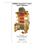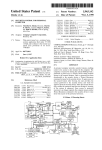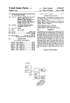
1
US 20060229746A1
(19) United States
(12) Patent Application Publication (10) Pub. No.: US 2006/0229746 A1
(43) Pub. Date:
Ollis et al.
(54)
MODULAR CONTROLLER FOR AN
Oct. 12, 2006
Publication Classi?cation
ENVIRONMENTAL MANAGEMENT SYSTEM
(51)
(76) Inventors: Je?rey D. Ollis, Dresher, PA (U S);
John M. Coogan, Lansdale, PA (US);
James A. Panacek, North Wales, PA
(Us)
(52)
Correspondence Address:
(2006.01)
(2006.01)
U.S. c1. ............................... .. 700/65; 700/66; 700/19
(57)
GENERAL INSTRUMENT CORPORATION
DBA THE CONNECTED
HOME SOLUTIONS BUSINESS OF
ABSTRACT
A controller is provided for an environmental management
system. The system includes a transceiver for transmitting
signals to and receiving signals from at least one environ
mental sensor or actuator over a network and a processor for
MOTOROLA, INC.
interpreting received signals and generating signals to be
101 TOURNAMENT DRIVE
transmitted over the Wireless network based upon at least
one environmental management function. A plurality of
HORSHAM, PA 19044 (US)
(21) Appl. No.:
11/254,422
(22) Filed:
Oct. 20, 2005
ports is also provided, each for receiving a plug-in compo
nent that provides information to implement a speci?c
environmental management function. The system also
includes a user interface operatively associated With the
Related US. Application Data
(60) Provisional application No. 60/669,101, ?led on Apr.
7, 2005.
processor and the plurality of ports for adjusting user
controllable parameters. The user-controllable parameters
are determined, at least in part, by at least one of the plug-in
components When operationally inserted into one of the
ports.
g
20
Int. Cl.
G05B 11/01
G05B 19/10
fr. 0
REMOTE
SENSOR
13
CONTROLLER
CENTRAL
TRANSCEIVER
2O
LOCAL BUS
EXTERNAL
NETWORK
INTERFACE
REMOTE
SENSOR
22
REMOTE
SENSOR
LOCAL
SENSOR
DlSPLAY/
KEYPAD
ALARM N 26
22
20
24
REMOTE
SENSOR
LOCAL
SENSOR
Patent Application Publication Oct. 12, 2006 Sheet 1 0f 4
l_<zm.xw mO<uEPZ_
#N /
VE2O.F05MZ4
m
w
j
O
F
Z
?gfz.
US 2006/0229746 A1
mm21\4(12
on
mm
fr
r3
mOwz
mmFOEmONOwZm
Patent Application Publication Oct. 12, 2006 Sheet 2 0f 4
US 2006/0229746 Al
mw>5om>o
.vNONON
/
/
6KwSK:5orm
/
f
f
f
2m0oE8g5:%n2;mw
6520
oww0mm
éwm:z>2w;:
/
f
f
2:Q0z3<¢
SN
/
EozHc9km6o
0mm
/
Patent Application Publication Oct. 12, 2006 Sheet 4 0f 4
/
six/rrs”
:
/
MPG-2m Owzm
ow
US 2006/0229746 A1
w.OE
MmIAONFZ
mm
Oct. 12, 2006
US 2006/0229746 A1
MODULAR CONTROLLER FOR AN
ENVIRONMENTAL MANAGEMENT SYSTEM
STATEMENT OF RELATED APPLICATION
[0001]
This application claims the bene?t of US. Provi
sional Application No. 60/669,101, ?led Apr. 7, 2005, Which
is incorporated herein by reference in its entirety.
programmable, in Which case a separate user interface may
be implemented by a personal computer or the like. Systems
may be programmed using either a simple command lan
guage or using a graphical user interface that requires a
computer With a monitor. These systems are often expensive
and require substantial investment by the user in time and
energy to install and modify programming. To enter and/or
change a program, a user must consult a user’s manual or
call a programming specialist. Hence, in comparison to
FIELD OF THE INVENTION
some security systems, these systems can be dif?cult to
[0002] The present invention relates generally to environ
install and adapt to changing needs. Moreover, they are
mental management systems such as security and automa
dif?cult to expand by adding neW controlled devices or neW
tion systems, and more particularly to a controller for
softWare to add functionality.
providing ?exible and incremental expandability of envi
ronmental management systems.
quite distinct from the home automation market. For
BACKGROUND OF THE INVENTION
[0003]
In residential and commercial environments there
are many stand-alone devices and often one or more indi
vidual environmental management systems functioning
independently. For instance, electronic security systems are
relatively common in residential and commercial environ
ments. Individuals and families, in particular, desire a secu
rity system that monitors a de?ned premises and/or envi
ronment, to prevent or deter theft, burglary and robbery. In
addition, there is a desire to monitor and detect other de?ned
conditions and, in response to a detected condition, generate
a Warning. These other potentially haZardous conditions or
threats include, for example, ?re haZards, carbon monoxide
and poWer failure and electricity outages.
[0004] A conventional security system for use in a resi
dence, for example, includes one or more keypads With
displays and a central control panel, Which in some cases is
remotely located from the keypads and displays. A number
of sensors for detecting various conditions are arranged in
the home or premises. In legacy security systems, the
sensors are most commonly connected to the control panel
by Wired means. The sensors may be of various types
designed to detect a variety of conditions. More recently,
Wireless security systems have become available. The sen
sors are generally relatively simple devices having tWo
operational states represented by a contact that is either in an
open or closed state.
[0005]
In addition to security systems, home automation
systems are another type of environmental management
system that are becoming more readily available in resi
dences. Home automation systems, or home management
systems as they are sometimes called, enable control of
lighting, heating and air conditioning, WindoW shades or
curtains, pool heaters and ?ltration systems, laWn sprinklers,
ornamental fountains, audio/visual equipment, and other
appliances. Home automation systems range from relatively
[0007] Traditionally, the security system market has been
example, not only do most security systems fail to provide
the control capabilities offered by home automation systems,
their monitoring abilities are also usually quite limited,
typically to sensors that are either “on” or “off.” Thus, for
instance, feW security systems even have the capability to
monitor and report something as simple as the ambient
temperature of the monitored premises. In part this market
segmentation arises from the different demands placed on
the tWo different types of systems. For instance, security
systems must be highly reliable and meet stringent regula
tory and other requirements, something Which is generally
not necessary for automation systems. Security system con
trollers are generally designed to interface With a very
limited range of sensors While home automation controllers
generally interface With a large number of different devices.
Additionally, security system controllers generally offer
unidirectional communication betWeen the sensors and con
troller, Whereas automation system controllers more com
monly offer bidirectional communication With various
devices.
[0008] Even Within the home automation market itself,
there is signi?cant market segmentation because most of the
automation control manufacturers address narroW, vertical
market segments, and use proprietary interfaces to protect
their market. For example, some leading control manufac
turers offer systems that focus on heating, ventilation, and air
conditioning (HVAC) systems control. These manufacturers
have little interest in controlling lighting, entertainment
systems, and the like as these markets are entirely foreign to
them. Other manufacturers make, for example, home enter
tainment controllers that integrate various video and audio
components, but the primary focus has been to offer inte
grated control over only their oWn components. As a result,
consumers face an array of control systems that do not
interoperate, and that have proprietary interfaces that are
dif?cult to understand and program. That is, the use of
multiple platforms generally means that the interfaces are
inconsistent With each other in the manner in Which controls
simple systems that control one or a feW functions in a home
are accessed, displayed and operate so that a consumer must
to more elaborate systems that control multiple, disparate
features.
learn the unique interface features of each system. Hence, as
[0006]
In general, a home automation or control system
comprises one or more controlled devices, one or more
controllers, and a communication link coupling a controller
to a controlled device. The controllers may be directly
programmable, in Which case they include some form of
user interface for setting sWitches, event timing, and the like.
Alternatively, the controllers may be indirectly or remotely
more systems are added, the complexity for the consumer
increases signi?cantly as neW control interfaces must be
added and learned.
[0009] Recently, some efforts have been made to provide
integrated security and automation systems. In addition to
the simpli?cations that arise from using a single platform,
this combination of systems offers enhanced functionality
and features that neither provide on their oWn. For instance,
US 2006/0229746 A1
home automation systems may be integrated With a home
security system so that When a ?re alarm is raised, for
example, internal and external lights Will be turned on. An
example of such a system is Home Automation Inc.’s Omni
Automation and Security System, Which includes a control
ler that can support both security and automation needs.
[0010]
The consumer is thus currently faced With three
primary choices When considering installation of security
and/or automation systems. The consumer may purchase
just a security system, just an automation system or a system
such as the Omni Automation and Security System that
provides both security and automation. If the consumer
purchases either a dedicated security or automation system,
future expansion of the system to include the other is
limited, thus requiring the purchase of a separate and inde
pendent system. On the other hand, if the consumer pur
chases an integrated security and automation system, he or
she may be purchasing a system that is more capable, and
hence more expensive, than their current requirements
demand.
[0011] Accordingly, it Would be desirable to provide a
system that is ?exible, interoperable With a variety of
existing or legacy systems, and Which alloWs for incremen
tal or modular expansion to provide additional functionality
as desired.
BRIEF DESCRIPTION OF THE DRAWINGS
[0012]
FIG. 1 shoWs an example of a residential security
system.
[0013]
Oct. 12, 2006
1 is already present in a residence and that the resident
desires to expand the system to include automation func
tionality. HoWever, the same principles apply to a situation
in Which a home automation system is initially present and
the resident Wishes to expand the system to include security
functionality. In other cases the resident may simply desire
to expand the capacity of the automation or security system
by alloWing it, for instance, to monitor, say, 40 sensors
instead of merely 20 sensors. Moreover, the security system
is assumed to be largely a Wireless system in Which RF
communications is used for all or some of the devices. As
shoWn, the security system 10 comprises a central control
unit 12, a central transceiver 14 (Which in some cases may
be eliminated and replaced by a receiver incorporated in the
central control unit 12), a console display/keypad 18, a
plurality of remote sensors 20 and local sensors 22, an
external netWork interface 24 and an alarm 26. The remote
sensors 20 may Wirelessly or hard-Wired to the central
transceiver 14, Which communicates With the central control
unit 12 via a Wireless protocol. The central control unit 12
also communicates With the console display/keypad 18 over
a Wireless link. The central control unit 12 is connected to
the external netWork interface 24 (e.g., an autodialer to
communicate over the public sWitched telephone netWork or
a data connection to communicate over the Internet) and the
alarm 26 either Wirelessly or via a local bus such as local bus
30. The central control unit 12 optionally may also be
hardWired to one or more local sensors 22.
[0018] Currently available Wireless security systems use
FIG. 2 is a logical diagram of a modular controller.
[0014] FIG. 3 is a block diagram representing a hardWare
vieW of the modular controller depicted in FIG. 2.
[0015] FIG. 4 shoWs the modular controller of FIGS. 2
and 3 incorporated into the security system shoWn in FIG.
1.
any of a variety of different communication standards. For
example, such systems may use, Without limitation, IEEE
802.11 (e.g., 80211a; 80211b; 802.11g), IEEE 802.15 (e.g.,
80215.1; 80215.3, 80215.4), DECT, PWT, pager, PCS,
Wi-Fi, BluetoothTM, cellular, and the like. While the Wireless
security systems, and hence Wireless controllers employed
in such systems, may encompass any of these standards, one
particularly advantageous netWork protocol that is currently
DETAILED DESCRIPTION
groWing in use is ZigBeeTM, Which is a softWare layer based
[0016] In general, security and automation systems may
on the IEEE standard 80215.4. Unlike the IEEE 802.11 and
be used to provide security and automation to a home, of?ce,
or other type of commercial or residential building. In the
residential context, the systems establish a home netWork
that controls, coordinates, facilitates, and monitors user
designated activities Within the home. The systems may also
provide compatibility betWeen external and internal net
Works, systems, and appliances. As described in more detail
beloW, a controller is provided that is modular in construc
tion to alloW easy expansion and customiZation. The modu
lar controller can be retro?tted for use in existing structures
With legacy systems to provide enhanced functionality With
out the need for drastic remodeling, added Wiring, or com
plicated installation/customiZation, and can simplify instal
lation, Whether performed by the resident or a professional
installer. Moreover, the modularity of the controller provides
for easy customiZation for either commercial or residential
use. Expansion can be accomplished by adding neW plug-in
components or modules to the controller. Although the
folloWing examples are primarily described With reference
to home applications, the described devices and concepts
also are applicable for commercial use.
Bluetooth standards, ZigBee offers long battery life (mea
sured in months or even years), high reliability, small siZe,
automatic or semi-automatic installation, and loW cost. With
a relatively loW data rate, 80215.4 compliant devices are
expected to be targeted to such cost-sensitive, loW data rate
markets as industrial sensors, commercial metering, con
sumer electronics, toys and games, and home automation
and security. For these reasons ZigBee may be particularly
appropriate for use in both Wireless security systems and
Wireless home automation systems.
[0019] ZigBee-compliant products operate in unlicensed
bands WorldWide, including 2.4 GHZ (global), 902 to 928
MHZ (Americas), and 868 MHZ (Europe). RaW data
throughput rates of 250 Kbps can be achieved at 2.4 GHZ (16
channels), 40 Kbps at 915 MHZ (10 channels), and 20 Kbps
at 868 MHZ (1 channel). The transmission distance generally
ranges from 10 to 75 m, depending on poWer output and
environmental characteristics. Like Wi-Fi, Zigbee uses
direct-sequence spread spectrum in the 2.4 GHZ band, With
offset-quadrature phase-shift keying modulation. Channel
Width is 2 MHZ With a 5 MHZ channel spacing. The 868 and
[0017] For purposes of illustration the folloWing example
900 MHZ bands also use direct-sequence spread spectrum
Will assume that a security system of the type shoWn in FIG.
but With binary-phase-shift keying modulation.
Oct. 12, 2006
US 2006/0229746 A1
[0020] Given an installed security system such as
described above in connection With FIG. 1, home automa
tion functionality may be provided by the addition of an
adjunct, modular controller. As discussed in more detail
beloW, the modular controller may be used not only to
extend an installed security or automation system, it may
also be used as the foundation of an integrated system that
offers security functionality, automation functionality, or
both. The functionality may all be deployed in the initial
system or it may be added incrementally. That is, the
modular controller can be used to overcome the problem that
arises When a resident Wishes to expand either a security or
automation system With capabilities that Were not originally
provided. Moreover, the security system may even operate
in conformance With one Wireless standard While the auto
mation system may operate in conformance With a different
Wireless standard.
[0021]
FIG. 2 is a logical diagram of one embodiment of
a modular controller 200. Modular or con?gurable function
ality is implemented at the application layer by one or more
plug-in components such as plug-ins 2101-2105. The plug-in
components may be physically implemented as user insert
able and removable cards (e.g., ?ash cards, PCMA cards),
modules, and the like. The form factor of the plug-ins may
90, programming port 92, and local bus 94 (corresponding
to local bus 30 in FIG. 1). Local bus 94 may also be used
to communicate With any local sensors, actuators, or net
Worked devices that may be employed. RF front-end trans
ceiver 84 may be compliant With one or more Wireless
formats. In some cases the front-end transceiver 84 may be
compliant With the ZigBee standard as Well as With at least
one other Wireless standard commonly used in legacy secu
rity or automation systems (e.g., IEEE 802.11). In other
cases the transceiver 84 may be able to operate in conform
ance With a number of different Wireless standards With the
use of appropriate plug-in components. If employed, local
bus 94 may include, for example, one or more analog-to
digital inputs, one or more digital-to-analog outputs, one or
more UART ports, one or more Serial Peripheral Interface
(SPI) and/or one or more digital I/O lines (not shoWn). The
network controller may also include RAM port 98 and ROM
port 100 (or a single port for both) for, among other things,
upgrading softWare residing in the microprocessor 86 (as
opposed to upgrades performed by replacement of plug-in
components, discussed beloW). User interface 95 (e.g., a
keypad/display unit) functions at the application level of
FIG. 2 and alloWs control of the various user-adjustable
parameters of the modular controller 200.
conform to a Well-established standard or it may be propri
[0025]
etary. The plug-in components may be implemented on a
With a great degree of ?exibility When initially purchasing a
single integrated circuit, such as an application speci?c
integrated circuit (ASIC). HoWever, the components may
also be readily implemented on multiple separate integrated
system. For example, if the consumer is in immediate need
of a security system, the consumer can purchase the modular
circuits or in softWare operating on a general purpose
With the associated sensors and the like). If at a later time the
processor located in the modular controller 200. The appli
cation layer may be a native graphical user interface (GUI)
202 or Web broWser 204 that are con?gurable by each of the
consumer Wishes to install an automation system, the con
The modular controller 200 provides a consumer
controller 200 With only the security plug-in 2102 (along
sumer can simply purchase the home automation plug-in
210, (along With the associated monitors, actuators and the
different plug-in components. Illustrative special purpose
like). In this Way the consumer only needs to purchase as
plug-in components include a home automation component
much equipment as is necessary to serve his or her imme
2101, a home security component 2102, and possibly any of
diate needs, Without limiting the future expandability of the
a variety of other components such as an intercom compo
system.
nent 2103 for providing telephony-type services throughout
all or part of the premises or an audio component 2104 for
playing audio ?les (e.g., music) throughout all or part of the
premises.
[0022] The plug-in components 2101-2105 operate in con
formance With an application programming interface (API)
layer that provides access to services available from the
operating system (OS) 250 and augments those services that
the OS provides. The API layer may be implemented in a
variety of different Ways, such as With Universal Plug-and
Play protocols and procedures 220, ?ash processes 230
related to a Macromedia FLASH programming environ
ment, and/or Web server products 240.
[0023] The API layer, via the OS layer 250, controls the
driver layer 260. The driver layer 260, in turn, interfaces
With the various hardWare components of the controller such
as a microprocessor, hardWare communication interfaces to
sensors, actuators, and the like. Drivers may be added or
removed as needed to support additional or updated func
tionality.
[0026] The modular controller 200 also provides the con
sumer With a number of different upgrade paths, depending
on the equipment that is already in place. For instance, if the
legacy equipment includes the modular controller itself,
upgrading to provide automation features is a simple matter
of purchasing additional plug-in components along With any
associated peripheral equipment. On the other hand, if the
legacy system is a dedicated independent security system (or
automation system) of a conventional type, the modular
controller 200 can be incorporated into the legacy system
With the use of an additional plug-in component that is
con?gured to alloW the modular controller to interoperate
With the legacy controller. In other cases the legacy equip
ment can be upgraded to provide more capacity so that the
system can monitor more sensors (in the case of a security
system) or control more devices (in the case of an automa
tion system). An example of such an arrangement is shoWn
in FIG. 4, in Which modular controller 200 has been
incorporated into the security system shoWn in FIG. 1. In
FIGS. 1-4 like elements are denoted by like reference
numerals. Also shoWn in FIG. 4 are netWorked devices 28
that are in communication With and under the control of the
[0024] FIG. 3 is a block diagram representing a hardWare
vieW of the modular controller 200 depicted in FIG. 2. The
modular controller 200 includes an antenna port 82, RF
front-end transceiver 84, one or more plug-in ports 601, 602,
modulator controller 200. Such netWorked devices include,
Without limitation, netWorked appliances such as coffee
makers, ovens, lights, television and stereo units, media
603, . . . 60D, microprocessor 86 having ROM 88 and RAM
centers.
Oct. 12, 2006
US 2006/0229746 A1
includes a plug-in 2105, referred to herein as a bridge
[0030] Although various embodiments are speci?cally
illustrated and described herein, it will be appreciated that
plug-in, which allows modular controller 200 to interoperate
modi?cations and variations are covered by the above
with legacy controller 12. Bridge plug-in 2105 may provide
two levels of interoperability. On the physical level, bridge
teachings and are within the purview of the appended claims
without departing from the spirit and intended scope of the
invention. For example, while modular functionality has
been described in terms of the provision of plug-in modules,
[0027]
Referring to FIG. 4, modular controller 200
plug-in 2105 may convert between a communication format
employed by the legacy security system and the native
communication format employed by the modular controller
200 for the system that is to be added. For instance, the
security system may use a low power, low bandwidth format
such as IEEE 80215.4 while the automation system may use
another wireless local access network (WLAN) format such
as IEEE 802.11, a cellular based communication format
(e.g., CDMA, TDMA, GSM), and the like. In addition to
physical interoperability, bridge plug-in 2105 may also
provide application level interoperability so that legacy
controller 12 and modular controller 200 can use and
respond to information received from one another. For
this same functionality can be provided by software com
ponents or modules that are downloaded directly to the
controller without the need to add any additional hardware
components to the controller. Moreover, while the environ
mental management system and controller have been
described in terms of a wireless system and controller, in
some cases the environmental management system and
controller may operate in a wired manner.
1. A controller for an environmental management system,
comprising:
example, if a signal is generated by a security sensor 20
indicating that a door or window has been opened, the
legacy system will use that signal to activate the alarm 26
and notify the appropriate agency or entity using external
network interface 24. Likewise, modular controller 200 may
a transceiver for transmitting signals to and receiving
signals from at least one environmental sensor or
actuator over a network;
use that same signal from the security sensor to turn on lights
a processor for interpreting received signals and generat
ing signals to be transmitted over the wireless network
or activate a camera or other devices under control of the
based upon at least one environmental management
modular controller 200. Depending on the level of sophis
function;
tication of the bridge plug-in 2015, the modular controller
200 may also be able to activate and deactivate features of
the legacy security system or communicate information
through the legacy security controller 12. For instance, if in
response to a security sensor 20 the modular controller 200
activates a camera, the data from that camera may be
forwarded from the modular controller 200 to the legacy
security controller 12, which may in turn transmit the data
using external network interface 24 to the same agency or
entity that is noti?ed when a security sensor indicates
unauthoriZed entry.
[0028] The manufacturer of the modular controller 200
may also manufacture a variety of different bridge plug-ins
for various legacy security systems to enhance its ?exibility.
Alternatively, or additionally, the manufacturer of the legacy
security system or even a third party may provide bridge
plug-in components for the modular controller 200. In this
way the ?exibility and number of compatible legacy systems
a plurality of ports each for receiving a plug-in component
that provides information to implement a speci?c envi
ronmental management function;
a user interface operatively associated with the processor
and the plurality of ports for adjusting user-controllable
parameters, said user-controllable parameters being
determined, at least in part, by at least one of the
plug-in components when operationally inserted into
one of the ports.
2. The controller of claim 1 further comprising a plurality
of plug-in components selectively insertable in and remov
able from each of the plurality of ports, each of the plug-in
components being con?gured to implement, in association
with the processor, a speci?c environmental management
function.
3. The controller of claim 1 wherein said transceiver and
said network are in communication in a wireless manner.
4. The controller of claim 1 wherein one of the plurality
with which the controller operates can be increased still
further.
of plug-in components is con?gured to implement function
ality associated with an environmental security system.
[0029] A number of other bene?ts arise from the use of a
modular controller as described above. For example, the
manufacturer may occasionally upgrade one or more the
of plug-in components is con?gured to implement function
plug-in components to provide advanced features not pre
viously available or even contemplated. For example, if
lighting were eventually to become available in which the
user could control not only its intensity, but also its color, it
would be desirable if in addition to simply turning the
lighting on and off and adjusting the dimming level, the
automation system could also control the color of the
lighting. The enhanced functionality can be readily achieved
by providing the user with an upgraded automation plug-in
module (e.g., module 210,) that expands the message set
de?ning control of lighting from one that refers only to
intensity to one that speci?es color and intensity.
5. The controller of claim 2 wherein one of the plurality
ality associated with an environmental automation system.
6. The controller of claim 2 wherein another of the
plurality of plug-in components is con?gured to enhance
capacity of the environmental management system.
7. The controller of claim 1 further comprising a bridge
plug-in component con?gured to facilitate interoperability
with a legacy environmental management system.
8. The controller of claim 7 wherein said interoperability
facilitated by the bridge plug-in component includes physi
cal layer and application layer interoperability.
9. A method for upgrading a pre-existing environmental
management system that performs a speci?c environmental
management function, comprising:
Oct. 12, 2006
US 2006/0229746 A1
providing a modular controller for an environmental
12. The method of claim 10 Wherein one of the plurality
management system that performs a second environ
mental management function, said modular controller
having a plurality of ports each for receiving a plug-in
component; and
of the plug-in components is con?gured to implement func
tionality associated With an environmental security system.
inserting at least one plug-in component into one of the
ality associated With an environmental automation system.
14. The method of claim 9 Wherein one of the plurality of
plurality of ports, said plug-in component being con
?gured to provide at least application level interoper
ability betWeen the pre-existing environmental man
agement system and the modular controller so that
Wireless signals communicated therebetWeen are cor
rectly interpreted.
10. The method of claim 9 further comprising the step of
inserting a second plug-in component into one of the plu
rality of ports for con?guring the modular controller to
perform the second environmental management function.
11. The method of claim 9 Wherein said modular control
ler is a Wireless controller.
13. The method of claim 10 Wherein one of the plurality
of plug-in components is con?gured to implement function
plug-in components is con?gured to enhance capacity of the
environmental management system.
15. The method of claim 9 further comprising the step of
inserting a bridge plug-in component con?gured to facilitate
interoperability With a legacy environmental management
system.
16. The method of claim 15 Wherein said interoperability
facilitated by the bridge plug-in component includes physi
cal layer and application layer interoperability.
*
*
*
*
*