1
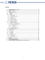
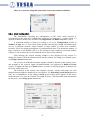
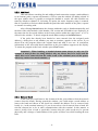
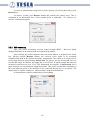
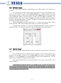
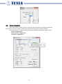
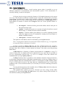
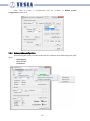
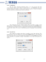
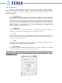
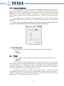
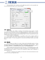
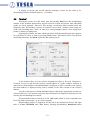
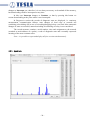
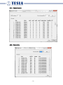
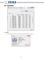
TERAview User Manual August 2015 -1- -2- Content 1. PROGRAM EXECUTION .................................................................................. - 5 1.1. Basic Window .................................................................................................... - 5 2. FILE ....................................................................................................................... - 6 3. CONFIGURATION .............................................................................................. - 6 3.1. PC link................................................................................................................ - 6 3.2. IQRF................................................................................................................... - 7 3.2.1. IQRF Mode ..................................................................................................... - 7 3.2.2. Mesh Configuration ........................................................................................ - 8 3.2.3. Add Bond ........................................................................................................ - 9 3.2.4. Remove Bond.................................................................................................. - 9 3.2.5. RSSI measuring ............................................................................................ - 10 3.2.6. RF Power Change ......................................................................................... - 11 3.2.7. Channel Change ............................................................................................ - 11 3.3. Measuring System ........................................................................................... - 12 3.3.1. System Configuration ................................................................................... - 13 3.3.2 Radon probes configuration .......................................................................... - 14 3.3.2.1 Initialization .......................................................................................... - 15 3.3.2.2 Date & Time ......................................................................................... - 15 3.3.2.3 Parameters ............................................................................................... - 16 3.3.3 Actuator Configuration ................................................................................. - 17 4. MEASUREMENT............................................................................................... - 17 4.1. Probes ............................................................................................................... - 17 4.1.1. Spectrum ....................................................................................................... - 18 4.1.2. Records ......................................................................................................... - 18 4.2. Terminal........................................................................................................... - 19 4.2.1. Spectrum ....................................................................................................... - 20 4.2.2. Radon Records .............................................................................................. - 21 4.2.3. Diagnostics .................................................................................................... - 21 4.2.4. Terminal Records .......................................................................................... - 22 5. ABOUT ................................................................................................................ - 22 6. TERMINAL SECTION...................................................................................... - 23 7. ACTUATORS SECTION .................................................................................. - 23 8. RADON PROBES MEASURED VALUES SECTION ................................... - 24 - -3- -4- TERAview program is intended for configuration, control, display and export of radon measuring network results. The program is directly executable, so it requires no installation. The following description corresponds to version 3.01 V2+. 1. PROGRAM EXECUTION Copy TERAview program to the working folder on your PC and connect your computer via RS232 or USB port with terminal unit. The program has a default automatic setting of the communication port, thus after starting up the basic window appears, where in the notification area (lower right corner) the port used for communication is displayed. Beware! Using the USB port, USB driver must be installed on your computer. A functional driver is supplied together with this program. Connecting RS232, it is necessary to use a cable, "extension cord" type, i.e. straight through (not crosslinked). 1.1. Basic Window In the basic window a measurement is configured, started up and stopped, a state of the entire system is displayed. The window is divided into four or five sections, depending on whether an actuator is assigned to the system. After starting up the program, in the basic window the followings appear: - Menu Bar with pull-down menus of Configuration, Measurement and Information about application - Terminal section - notification area. Only having started up a measurement (see the description of Terminal section), the sections of the elements taking part in the measurement appear, i.e.: - section of Actuators (if they are in the system) - section of Radon probes measured values - -5- 2. FILE After opening, the pull-down menu appears with one item Exit, which allows closing the program. 3. CONFIGURATION After opening, the pull-down menu appears with the following menu items: - PC link - IQRF - Measuring system 3.1. PC link After opening, the window appears where is possible to select the port for communication. It is recommended to keep the setting – Automatically. The program itself finds a suitable port; its number appears in the notification area. In addition, it is possible to set up communication timeout in the window; the value of 200 msec is preset as the default value. There is no reason for a change of this value in normal user operation. -6- 3.2. IQRF In this menu the settings related to the radio network could be performed. It is necessary to include each element (probe, actuator and repeater) in the network and to assign a network (mesh) address to it which provides its identification in the network. This process is called bonding. Besides of the mesh address every element has so called peer-to-peer (P2P) address which specifies physically an individual radio module in every element. The mesh address is not associated directly with the element serial number; by this means one element could have various mesh addresses depending on a configuration. A serial number and P2P address are stated on labels on an element where is possible to note down the assigned mesh address. Note: it is generally true that in the beginning of any setting which affects the parameters of the probe or network while a measurement is running, a dialog box appears where you have to confirm that this measurement can be interrupted. After moving the cursor over IQRF the submenu pulls down with several items 3.2.1. IQRF Mode This item allows entering, changing and saving the operation mode of IQRF module (XLP, LP, XSP, STD). A mode selection affects a communication speed and a consumption of the module. Radon probes are designed for the minimal power consumption, so they operate in XLP mode (Extra Low Power). After clicking, the window appears where current mode of the IQRF module in the terminal is displayed. If the mode is to be changed for any reason, select it in the list box and confirm by pressing Save button. Pressing Close button returns the program to the basic window. -7- There is no need for using this item under normal operational conditions. 3.2.2. Mesh Configuration The information regarding the configuration of the entire mesh network is concentrated in this item; the configuration could also be changed to a certain extent. To open the window with the basic sections of Configuration and Bonds overview, click it. A maximum number of hops for routing is set up in Configuration section in Number of hops box, i.e. how many points (probes and repeaters) might information pass over to a particular element. Larger number of hops enables to create more extensive networks, but it also brings prolongation of communication time. The maximum number of hops is equal to 16, the default value is 4. The setting of value 0 signifies a network without routing, i.e. all elements have to be within the direct reach of the terminal. After entering, the current working channel is also displayed in the section. To change the channel, click the channel button and the window for setting up a channel opens, see Change channel menu item. An overview of all bonded elements together with their function in the system, power and strength of the received signal (element/terminal) are displayed in Bonds overview section. To update the data press Enter button. A course of entering progress is displayed in the lower notification area. The functions in the system (not assigned, repeater, actuator and probe) for each bonded element might be changed in its relevant box, see Measuring system/assign as menu item. As a confirmation of any change, Saved green backlit notice appears in the lower notification area. To open the window for setting of power, click the button with information on the power, see Change power menu item. -8- 3.2.3. Add Bond This item allows searching for and adding a bond connection (assign a mesh address) to an element (probe, repeater and actuator). Click to open the window for adding a bond. In the open window there is possible to assign the channel to search. All radio modules are tuned by default to channel 52. Selecting All option, the entire frequency range is scanned, thus it is possible to find out which channel the particular radio module in the probe, repeater or actuator is working with. After clicking Search button, the element within the reach is found automatically and the data of the radio module (serial number, SW version and P2P address) are displayed. At the same time the free mesh address at the lowest position within the range from 1 to 127 is offered in the window. To bond, assign the mesh address and press Set Bond button. If the probe has already been bonded to some network (has the assigned mesh address), a dialog box to ask whether you want to continue, appears on the screen. If you choose Yes, the program deletes the original bond and adds a new one. In conclusion, information on the successful bond connection at the given address appears on the display. To return the program to the basic window press Close button. Attention!! When bonding, a bonded element must always be only one. For example, if more probes are being bonded, only one always has to be active and the others have to be removed from the radio reach of the terminal (turn off the power, take away, enclose in a metal container ...) 3.2.4. Remove Bond In this item you could remove the element with the given address from the network (remove from the bond). Having opened the window, you could assign a mesh address to remove the bond and choose in the check box whether the address is to be removed only locally (i.e. in the terminal memory). If you do not select a local removal from a bond, the relevant element has to be in radio communication with the terminal. In this manner to remove locally from a bond is preferable, because then the probe needs not be present physically and a change of mesh address in the probe will have run while bonding the next time. -9- To enter an identification string from a probe memory (if present physically), press Read button. To remove a bond, press Remove button and confirm the control query. This is confirmed in an information box; if last bonded probe is unbonded, “No elements are bonded” information appears. 3.2.5. RSSI measuring This item allows measuring received signal strength (RSSI - Received Signal Strength Indicator) in an element with an assigned mesh address. After clicking, the window appears where the mesh address is assigned in the check box. Having pressed Measure button, the received levels begin to be measured simultaneously both in the element and in the terminal unit. The values of received level lie in the range between approximately 40 and 100. The figures are not relevant dB, but it is true that the larger the number, the higher the received level. If signal strength has not been measured or has been too low, Error FEh information box appears. In Insert delay box a pause between two measurements might be defined. This pause is particularly important in the event when the probe to be measured is not connected directly, but via a repeater. The default value is equal to 1000 msec, which complies with all measurements. A measurement could be completed by pressing Stop. - 10 - 3.2.6. RF Power Change This item allows changing a transmitting power of RF module in an element or a terminal. After clicking, the window appears where is possible to select a mesh address of the element, or the terminal (Term), or All in Mesh address box. All option makes sense only when setting up power, so that as this option takes place, Read button is no longer active. After assigning the address, the current power is read by pressing Enter. Furthermore, it is possible to select a new value of power in Power box and to set up this value in the chosen element by pressing Save button. As long as All address is selected, the selected value is set up in all the elements and the terminal. The power might be set up in eight stages (0 – 7) where one stage correlates with a change of about 2,5dB. The maximum power (stage 7) is equal to about 5 dBm. A default value of power is 7 and in the operating mode there is likely no point to change this value – this function is intended rather for debugging and testing purposes. 3.2.7. Channel Change This item allows setting channel (frequency) which the entire network will operate with. After clicking, the window appears where is possible to select a mesh address of the element or the terminal (Term) or All in Mesh address box and a particular operating channel (0 – 61) in Channel box. Priority should be given to use the channels 49 - 54. The default value is channel 52 (frequency 868,35 MHz). After pressing Save button, the selected element or the entire network tunes to the selected channel. ATTENTION!! Using this feature, you should be very careful. It is always best to retune the entire network at once. In the event of fault retuning, e.g. one probe has been retuning to another (unknown) channel, it is necessary to find it by scanning of all channels function in Add bond item. - 11 - 3.3. Measuring System This menu allows setting up and configuring the measurement, element parameters, time ratios; it is also possible to erase data memories in the probes and the terminal. After moving over Configuration menu item the submenu pulls down with the items - System configuration - Radon probes configuration - Actuators configuration - 12 - 3.3.1. System Configuration After clicking this window, several sections appear where is possible to set up different parameters of measurement and measurement system. If the measurement is currently running, it must be interrupted. In System function assign section the features of all bonded elements in the system are set up. The fact that an element is bonded, doesn´t imply this element takes part in the measurement. It needs not be a probe, but it could be a repeater or an actuator, or a bonded probe should not be for some reason assigned to the measurement. In Mesh address box a mesh address of element is chosen and in assign as box one of four possible features is selected not assigned – element with the given mesh address doesn´t take part in the system activity at all repeater– element will operate as a repeater of signal (if need be to extend the RF range, i.e. distance between network elements) actuator – element with the given address is a wireless switching element with relay output (receiver of command for turning on/off an actuator or another ventilation means) radon probe – element is an active probe The option for each address must be confirmed by pressing Save button. Note: An assignment should correspond with element hardware (e.g. it is impossible to assign the feature of actuator to a probe). In Timers section in Query time box the time elapsed between the respective communications between the terminal and elements is set up. The time is set in seconds in the range from 240 to 32400 (i.e. from 4 minutes to 9 hours). The value is saved by pressing Save button. In Batt time box a frequency of battery measurement for a repeater is set up. To conserve battery life, its voltage needs not be measured in every cycle, but it is possible to set up a measurement interval from 1 to 255 as a multiple of the time between the communications (set up in Query time box). In Sleep check box there is possible to select whether elements of the network have to fall asleep completely between individual communications or have not. Falling asleep of network elements between communications reduces a consumption of IQRF modules (about 25 µA in XLP mode for most of the time between communications), but it could cause problems in the event of manual control. (It is necessary to wait for awakening of network elements). To erase the data memory in the terminal, tick off History clear check box and press Save button in History of Measurement section. The terminal time could be set up in Terminal real time setting section either according to PC by pressing Copy PC time button, or by direct setting of date and time in relevant boxes and by pressing Set button. - 13 - Note: time in probes is synchronized with the terminal in Radon probes configuration menu item. 3.3.2 Radon probes configuration After moving the cursor over this menu item, the submenu with following items pulls down: - Initialisation Date & Time Parameters - 14 - 3.3.2.1 Initialisation This item allows initialising individual probes, i.e. to erase previous data from records memory (4096 records with the selected interval – see Parameters) and from spectrum memory (511 buffers, 12 hours each). The time of probe is set up in accordance with the terminal time simultaneously with the initialisation. After clicking the item, the window appears where is possible to assign a mesh address (either an individual address or all ones together) and after pressing Initialise button the initialisation is performed. After the completion the information box appears and displays a result of the activity. The course of initialization process is displayed in the notification area. 3.3.2.2 Date & Time After clicking, the window opens where is possible to set up date and time of the terminal (they are set up according to PC) by pressing Terminal button, as well as date and time of the probe (they are set up according to the terminal) by pressing Probe button. While setting up probes, it is possible to assign a mesh address or to set up all the probes (All option). - 15 - 3.3.2.3 Parameters This menu allows setting up probe parameters for measurement. After clicking, in the open window the mesh address of probe is selected and by means of Read and Save buttons it is possible to read probe parameters and save the changed ones. There are the following parameters: Discrimination the whole measured energy spectrum is divided into 96 channels and three adjustable discrimination levels divide the entire area into four sections. The value of radon concentration is determined from the second area, i.e. from the area lying between the first (left) and the second (middle) value of the discrimination level. The energy of impulses generated as a result of radon decay is precisely known, therefore through suitable settings of discrimination levels the useful impulses are separated from artefacts arising from interference etc. Calibration is the constant value for calculation of radon concentration based on the number of impulses. It is determined individually during a calibration of probe Limit is such a value of the radon concentration in which a relay (of actuator and/or of terminal) switches on/off. The limit value has specified hysteresis of about 10%, to avoid frequent switching on/off Gain allows shifting the energy spectrum left or right. It is determined individually when calibrating a probe (standard value is at about 100) Record time the duration of measurement between two records is set up in minutes. The default value is 60 (minutes), i.e. a record is created every hour. Attention!! Only Limit and Record time from the above-listed parameters are useradjustable!! A change of other parameters might cause malfunction and/or measurement errors. - 16 - 3.3.3 Actuator Configuration After moving the cursor over this menu item, Parameters submenu pulls down. If no actuators are bonded, after clicking No actuators are bonded notice appears, otherwise the window opens where is possible to select a mesh address of the actuator and after pressing Read button a state of relevant actuator is displayed. An actuator could be in on/off/Auto state. Its state is displayed in a dot menu and at the same is printed in the line above the buttons. The actuator state is changed by selecting appropriate item in the dot menu and a pressing Save button. Having carried out, an information box with the result of operation appears. Note: To provide proper operation of the whole system of measurement and regulation of radon concentration, the actuator has to be set to Auto state. 4. MEASUREMENT After clicking, the pull-down menu item appears with the following items - Probes - Terminal 4.1. Probes After moving the cursor over this menu item, the submenu appears with the items - Spectrum - Records These items allow downloading data from spectra memory or records memory directly from the probe. Each probe has memory for 512 spectra, (511 buffers in the memory and current buffer No. 1). The higher the number of the buffer, the deeper into the history. A spectrum is loading either for 12 hours, or until ˃ 255 impulses are counted in any channel. A new spectrum always starts downloading after 12 hours. A probe has a memory for 4096 records wherein time, a value of the radon concentration calculated as an average of 15 measurements with the interval of 4 minutes, a number of impulses over individual intervals given by discrimination levels, temperature, humidity and a state of high voltage source are recorded. - 17 - The downloaded values could be saved in .tab format which is easily exportable into Excel for further processing, e.g. in a form of graphs. 4.1.1. Spectrum After clicking, the window to display and download spectra appears. In Data download section we define the probe mesh address and determine which buffers we want to download. To import data from a probe, click Download button. On-line transmission from the probe takes some time, thus the downloading progress could be monitored in the lower notification area under the display part. If more buffers are downloaded, it is possible in Select data to display section to choose desired buffer which will be displayed in the form of graphs and tables in the main part of the window. To start saving process of data from downloaded buffers, press Save button. 4.1.2. Records After clicking, the window for records display and downloading appears. In Data download section we define the probe mesh address and determine which records (1 – 4096) we want to download. A downloading interval we could choose in the pull-down menu or put directly in the box. To download data from a probe, click Download button. On-line transmission from the probe takes some time, so downloading progress could be monitored in the lower notification area under the display part. If downloading of more records than the probe contains is selected, the warning box appears upon completion of downloading process. Records are displayed in the middle part of Records section and downloaded records could be saved by pressing Save button. - 18 - A display of spectra and records and the meaning of items are the same as for downloading from the terminal memory – see further. 4.2. Terminal Moving the cursor over this menu item and clicking Data item, the downloading window of the terminal data memory appears wherein records and spectra from individual probes are saved regularly. Moreover, this memory records data from terminal itself and diagnostic data. The memory capacity of terminal is more than 3 months, when using one probe with recording time 1 hour; an interval is correspondingly shorter, when using more probes or shorter recording time. Opening the window, the state which took place while downloading last time appears in it; therefore it is best to start by pressing Clear button. This button clears only the data downloaded last time, but doesn´t clear the data memory itself. In the window there are four sections designated as Spectra, Records, Diagnostics, Terminal. In Spectra and Records sections a mesh address of a probe could be selected. In each section a total number of downloaded data is displayed, in Spectra and Records sections the mesh address is displayed along with a number of the data relevant to the selected address. In each section there are View and Save buttons whereby the appropriate operation is selected. Moreover, in Terminal section the time information is displayed, showing, how far into the past downloading has reached. All downloaded values could be saved in .tab format which is easily exportable into Excel for further processing, e.g. in a form of graphs. Downloading progress is displayed on the left in the bottom line and on the right there is Clear, Download and Close button. Starting downloading, Download button - 19 - changes to Interrupt one, therefore it is not always necessary to download all the memory, but downloading could be interrupted at any time. In this case Interrupt changes to Continue, so that by pressing this button we resume downloading at the point where it was interrupted. In Diagnostics section the records of diagnostic state are displayed, i.e. start/stop, measurement, communication failures, state changes of local relay or network one (switching on/switching off) in case of exceeding/dropping below a set limit. Mere automatic changes of state are recorded, manual switching on/switching off relay is not considered. The record structure contains a serial number, time and assignment to the network (terminal or mesh address of a probe), a code of diagnostic state and a textually expressed meaning of the most common codes. Note: it is possible to open and display all four sections simultaneously. 4.2.1. Spectrum - 20 - 4.2.2. Radon Records 4.2.3. Diagnostics - 21 - 4.2.4. Terminal Records 5. ABOUT After opening this window basic information about the application appear. - 22 - 6. TERMINAL SECTION In this section the data from the terminal are displayed, the actuator or the relay placed directly in the central unit is set up; the measurement is started/ interrupted/resumed. Measurement: Start/Interrupt and Continue buttons By Start/Interrupt button a new measurement is started up/interrupted, i.e. by pressing Start, the measurement history is not downloaded from the probe to the terminal memory. To download and save the measurement history from the probe, use Continue button. If, for some reason, the measurement is interrupted for a longer time, it should be resumed by the Continue button, so as not to lose the data which the probe has measured in the meantime. Relay: In the pull-down window a state of the relay placed directly in the terminal unit is chosen - off/on/auto. Auto mode means the relay switches on/switches off when exceeding/dropping below a set limit (default limit is 200 Bq/m3); another value could be set up in Configuration/ Measurement system/ Probe configuration/ Parameters/ Limit menu. In this section data from the terminal are also displayed – temperature, pressure and humidity; the icons of relay state (actuator) and measurement state are displayed, as well as the icon with a battery voltage where is also indicated whether a charger is connected. A measurement state is also text-indicated – No measurement notice or information on time remaining until the next measurement – Query after xxx secs. For the time while the measurement is actually running, i.e. communication between the central office and network elements takes place, "Q" letter is displayed inside the measurement icon. Data from the central unit are restored in the interval up to 1 sec. 7. ACTUATORS SECTION In this section the data from individual external actuators are displayed. In the pulldown menu one from available mesh addresses is selected (mesh addresses of all the actuators assigned to the measurement are displayed) and in the window the data of this actuator are displayed: - Mode indicates the current actuator state (on/off/auto). An instantaneous actuator state in Auto mode is showed on the actuator icon in the right part of the section. The actuator switches on/switches off) in case of exceeding/dropping below a set limit (default limit is 200 Bq/m3); another value could be set up in Configuration/ Measurement system/ Probe configuration/ Parameters/ Limit menu. - Voltage displays the battery voltage. While falling the voltage below 3,2 V, the box turns red and a dialog box with the warning appears. Pressing Set button, Actuator configuration/ Parameters window opens where is possible to change the actuator settings. - 23 - 8. RADON PROBES MEASURED VALUES SECTION In this section the data from individual external probes are displayed. In the pulldown menu one from available mesh addresses is selected (mesh addresses of all the probes assigned to the measurement are displayed) and in the window the data of this probe is displayed. - Number of failures indicates a number of failed communications between the terminal and the probe. The first successful communication resets this value. The history could be read in Diagnostics section (Measurement / Terminal / Diagnostics) - Temperature indicates a temperature inside the selected probe - Humidity indicates relative humidity in percentages inside the selected probe - Voltage displays the probe battery voltage. Falling the voltage below 3,2 V, the box turns red and a dialog box with the warning appears - HV Check a number from 0 to 240 brings out a state of high voltage (HV) in a probe (number of impulses to HV source per 1 minute). The smaller is the number, the better. Larger numbers indicate a potential problem, such as high humidity - Radon displays a moving hourly average of radon concentration calculated from fifteen last four-minute intervals - Long term radon a moving daily average of radon concentration calculated from twenty four last hourly averages - 24 -