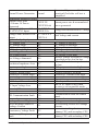
1
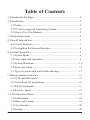
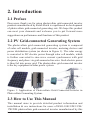
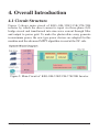
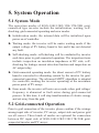
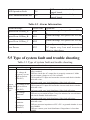
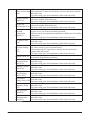
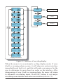
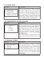
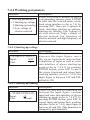
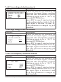
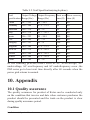
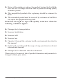
KSG-10K/12K5/15K/17K/20K
Solar Inverter
User Manual
201402 ︳Ver 1.0
Table of Contents
1. Introduction for Signs .................................................................... 4
2. Introduction .................................................................................... 5
2.1 Preface ..................................................................................... 5
2.2 PV Grid-connected Generating System .................................. 5
2.3 How to Use This Manual ........................................................ 5
3. Safety Instructions ......................................................................... 6
4. Overall Introduction ....................................................................... 7
4.1 Circuit Structure ...................................................................... 7
4.2 Description for External Interface ........................................... 8
5. System Operation ........................................................................... 9
5.1 System Mode ........................................................................... 9
5.2 Grid-connected Operation ....................................................... 9
5.3 System Shutdown ................................................................... 11
5.4 Error and Alarm...................................................................... 11
5.5 Type of system fault and trouble shooting ............................. 13
6. Human-machine Interface ............................................................. 15
6.1 LCD controlled panel ............................................................. 15
6.2 Networking for monitoring .................................................... 16
6.3 WLAN (optional) ................................................................... 17
6.4 Remote control ....................................................................... 17
7. LCD Operation Menu ................................................................... 18
7.1 Initialization ........................................................................... 18
7.2 Major cycle menu ................................................................... 18
7.3 User interface ......................................................................... 20
7.4 Setting .................................................................................... 20
Installation and Opertion Manual
1
7.4.1 Input mode ...................................................................... 21
7.4.2 Standard for electric network ......................................... 21
7.4.3 Remote CTRL................................................................. 21
7.4.4 Working parameters ........................................................ 22
7.4.4.1 Starting-up voltage.................................................. 22
7.4.4.2 Starting-up timelag ................................................. 22
7.4.4.3 Low voltage of electric network ............................. 23
7.4.4.4 High voltage of electric network ............................ 23
7.4.4.5 Low frequency of electric network ......................... 23
7.4.4.6 High frequency of electric network ........................ 24
7.4.4.7 Please starting-up again .......................................... 24
7.4.5 485 address ..................................................................... 24
7.4.6 485 baudrate ................................................................... 25
7.4.7 Display language ............................................................ 25
7.4.8 LCD backlight ................................................................ 25
7.4.9 Date/time ........................................................................ 26
7.4.10 History clearing ............................................................ 26
7.4.11 Password setting ........................................................... 27
7.5 Inquiry .................................................................................... 27
7.5.1 INV MODEL .................................................................. 28
7.5.2 MODEL SN .................................................................... 28
7.5.3 Firmware......................................................................... 28
7.5.4 RECORD ........................................................................ 29
7.6 Statistics ................................................................................. 30
7.6.1 Time statistics ................................................................. 30
7.6.2 Times of paralleling in .................................................... 30
7.6.3 Power peak ..................................................................... 31
Installation and Opertion Manual
2
7.6.4 Generated energy of that day .......................................... 31
7.6.5 Generated energy of that week ....................................... 31
7.6.6 Generated energy of that month ..................................... 31
7.6.7 Generated energy of that year......................................... 32
7.6.8 Gross generation ............................................................. 32
8. Installation..................................................................................... 33
8.1 Overview ................................................................................ 33
8.2 Mechanical installation .......................................................... 34
8.2.1 Installation introductions ................................................ 34
8.2.2 Mechanical dimension .................................................... 34
8.2.3 Packing .......................................................................... 36
8.2.4 Installation of Inverter .................................................... 36
8.2.5 Installation Location ....................................................... 37
8.2.6 Installation Procedure ..................................................... 37
8.2.7 Ambient requirement ...................................................... 39
8.3 Electric connection ................................................................. 39
8.3.1 Requirement for electric installation .............................. 39
8.3.2 Wire for alternating current connection .......................... 40
8.3.3 Wire for direct current connection .................................. 41
8.3.4 Wire for communication connection .............................. 42
8.4 Starting and closing ................................................................ 43
9. Technical Data............................................................................... 44
10. Appendix .................................................................................... 45
10.1 Quality assurance ................................................................. 45
Installation and Opertion Manual
3
1. Introduction for Signs
In order to make a better use of this manual, please read the following
sign explanation carefully.
Warning!
This sign indicates that it may cause danger to safety of
users and/or attentions or instructions for possible serious
damage to hardware.
Instruction!
This sign indicates important attentions required for good
operation of the system.
Installation and Opertion Manual
4
2. Introduction
2.1 Preface
Dear users, thank you for using photovoltaic grid-connected inverter
products manufactured by Kstar which is experienced in development
of photovoltaic grid-connected generating sets. We hope this product
can meet your demands and welcome you to put forward more
suggestions on performance and functions of this product.
2.2 PV Grid-connected Generating System
The photovoltaic grid-connected generating system is composed
of solar cell module, grid-connected inverter, metering devices and
power distribution system (as shown in Figure 1). The solar energy
is converted to DC electric power through solar cell module, which
is further converted to sine-wave current synchronous with grid
frequency and phase via grid-connected inverter. Such electric power
is then fed into power grid. The photovoltaic grid-connected inverter
is the key equipment in solar power system.
Figure 1: Application of Photovoltaic Grid-Connected Inverter in
Photovoltaic Generating System.
2.3 How to Use This Manual
This manual aims to provide detailed product information and
installation & use instructions for users of KSG-10K/12K5/15K/
17K/20K photovoltaic grid-connected inverter manufactured by this
Installation and Opertion Manual
5
company. Please read this manual carefully prior to use of this product
and store it properly in a place where it is convenient for installation,
operation and available for maintenance personnel.
3. Safety Instructions
► Please read this manual carefully prior to installation. This
company assumes no responsibility for quality assurance upon
equipment damage due to installation failing to follow instructions
in this manual.
► All operations and wiring shall be conducted by professional
electrical or mechanical engineer.
► Do not move other parts inside the machine case except the
binding post during installation.
► All electrical installations must conform to local standards for
electrical installation.
► Please contact with local appointed personnel for system
installation and maintenance if this equipment requires the
maintenance.
► Use of this equipment for grid-connected power generation must
be approved by local power supply departments.
► When the photovoltaic array is installed in the day, it shall be
covered with lightproof materials; otherwise the array end will
subject to high voltage under exposure of sunlight, thus causing
personal risk.
Warning! Ensure that the input DC voltage does not
exceed 900V since higher input voltage may damage
this equipment permanently and causing other losses,
under which circumstance, this company assumes no
responsibility for quality assurance and joint responsibility
Installation and Opertion Manual
6
4. Overall Introduction
4.1 Circuit Structure
Figure 2 shows main circuit of KSG-10K/12K5/15K/17K/20K
inverter by which the direct current is input via three-phase fullbridge circuit and transformed into sine-wave current through filter
and output to power grid. To make the photovoltaic array generate
in maximum power, the new type power devices are adopted for this
machine and the advanced MPPT algorithm is used at the DC side.
Figure 2: Main Circuit of KSG-10K/12K5/15K/17K/20K Inverter
Installation and Opertion Manual
7
4.2 Description for External Interface
5. DC-Switch
(Option)
1. DC Input
3. RS-232
6. WIFI port
4. RS-485
2. AC OUTPUT
Figure 3: Interface of KSG-10K/12K5/15K/17K/20K Inverter
■ Instructions for Interface
► 1: DC Input: DC input terminal, connected to positive and negative
electrode input of photovoltaic array respectively.
► 2: AC OUTPUT:AC output, spaced by three phases AC switch and
connected to L1, L2, L3, N and GND of three-phase grid.
► 3: Communication Interface RS232: connected with PC via joint
RS232.
► 4: Communication Interface RS485: wire RS485A/B is connected
with PC via converter RS485/ RS232.(When two or more inverters
are in parallel communication, 2P DIP switch beside RJ45 of the
last one should be “ON”. Or else, it may cause communication
interruption.That 2P DIP switch is on, means connecting a 120Ω
communication terminal resistance between the R/T + and R/T - )
► 5. DC switch: can judge the positive and negative electrode input
of photovoltaic array(option).
► 6. WIFI port.(option)
The inverter is equipped with WIFI port. If you need to
use WIFI function, please choose to use the External WIFI
& Ethernet Box. WIFI communication can be single or
network used, 32 PCs at most.
Installation and Opertion Manual
8
5. System Operation
5.1 System Mode
The operation modes of KSG-10K/12K5/15K/17K/20K gridconnected type inverter include the initialization, waiting, selfchecking, grid-connected operating and error modes.
► Initialization mode: the internal data will be initialized upon
power on of controller.
► Waiting mode: the inverter will be under waiting mode if the
output voltage of PV battery board is low and it has not detected
any fault.
► Self-checking mode: self-checking will be conducted by inverter
each time prior to grid-connected operation. The inspection items
include: inspection on insulation impedance at DC side, selfchecking for leakage current detection function and inspection on
AC output relay.
► Grid-connected operating mode: the direct current of PV battery
board is converted to alternating current by the inverter for gridconnected operation. The advanced MPPT algorithm is adopted
for controller, making the inverter operating at the maximum
power point of PV arrays.
► Error mode: the inverter will enter error mode when grid voltage/
frequency is abnormal or fault arises during grid-connected
process. At this time, it will stop transformation of electric energy
and cut away from the grid.
5.2 Grid-connected Operation
Prior to grid connection of the inverter, please confirm if the wirings
among input side of inverter, PV arrays, output side and power grid
are all correct. Three kinds of modes are optional for connection
between DC input side of KSG-10K/12K5/15K/17K/20K gridconnected inverter and PV arrays:
Installation and Opertion Manual
9
► Independent input mode: three groups of different PV arrays may
be connected to input end of inverter and independent MPPT
controller is available for each group of PV arrays to control gridconnected operation.
Figure 4: Independent Input Mode
► Parallel input mode: only one group of PV arrays is connected
with input end of the inverter, which is then connected to input
side of inverter via three groups of parallel input terminals.
Figure 5: Parallel Input Mode
► Mixed input mode: two groups of different PV arrays may be
connected to input end of inverter, where one group of PV arrays
is required to lead out two lines of parallel input terminal and
connected to terminal PV1/PV2 at input side of inverter, while the
other group is connected to terminal PV3 at input side of inverter.
Figure 6: Mixed Input Mode
Installation and Opertion Manual
10
Users are required to set the item “Input Mode” under
LCD menu correctly based on actual conditions of
photovoltaic generating system and confirm that the mode
of connection at input side is consistent with setting (refer
to 7.4.1).
If both input and output wirings are correct and the power grid is free
of abnormal conditions, the inverter will enter waiting mode. The
grid connection of inverter will be started fully automatic. After PV
voltage is higher than Vpv, count down for grid connection will be
started automatically for controller and prepare for grid-connected
operation after delayed for Td. Manual setting is available for both
Vpv and Td through LCD panel.
5.3 System Shutdown
If grid-connected power of inverter is smaller than 100W
continuously, the alarm of “zero power” will emerge. After alarming
for one minute, the inverter will cut away from the grid and reenter
waiting mode.
The inverter will cut away from the grid upon discovery of any
abnormal condition during the grid-connected process.
5.4 Error and Alarm
The error and alarm information of KSG-10K/12K5/15K/17K/20K
photovoltaic grid-connected inverter refer to the following table:
Table 5.1 Working conditions and fault/alarm message
Working conditions
Normal working status
Message display
Description
in English
Inverter OFF
No display
Inverter Stand-by
Stand-by
Self-test
Checking
Installation and Opertion Manual
PV voltage <180V,the inverter is
switched off
210V< PV voltage <350V(adjustable)
PV voltage >350V(adjustable),
the inverter get started and self-test
all modules
11
Normal Power Generation Normal
Monitoring parameter display
Instant Power Rate
XXXX W/
& Volume Of Power
XXXXX Kwh
Generated
Voltage And Current Of
DC: XXX.X
PV1/PV2/PV3 Input
VXXX.X A
Voltage And Current Of AC AC: XXX.X V
output
XXX.X A
System faulty display
AC Voltage Low
F00
AC Voltage High
F01
AC Frequency Low
F02
AC Frequency High
F03
Bus Voltage Low
F04
Bus Voltage High
F05
Bus Voltage Abnormal
F06
Insulation Impedance Low F07
Input current high
Reserved
Inverter Current High
Inverter DC Current High
Reserved
Heatsink Temperature High
AC Relay Abnormal
F08
F09
F10
F11
F12
F13
F14
PV Input Voltage Low
F15
Remote Off
Reserved
F16
F17
SPI Communication Fault
F18
Reserved
Leakage Current High
Self-Checking Failure Of
Leakage Current
F19
F20
F21
Consistency Voltage Fault
F22
Consistency Frequency
Fault
F23
Installation and Opertion Manual
Generate AC power and feed to
municipal Grid after self-test is
completed
Instant power rate & accumulated
power generated
Voltage and current from PV arrays
Grid Voltage and current
AC Voltage is too low.
AC Voltage is too high.
AC frequency is too low.
AC frequency is too high.
Bus voltage is too low.
Bus voltage is too high.
Positive voltage or negative voltage
is too high or too low on bus.
PV arrays Insulation impedance is
too low.
PV Input current is too high.
Reserved
Inverter current is too high.
Inverter DC current is too high.
Reserved
Heatsink temperature is too High.
AC relay is abnormal.
One of PV input is idle when
inverter is set on parallel mode.
Status of inverter is on remote off.
Reserved
Communication fault on control
board.
Reserved
Leakage current is too high.
Self-checking Failure of Leakage
Current.
Inconsistent voltage between
primary CPU and secondary CPU.
Inconsistent frequency between
primary CPU and secondary CPU.
12
DSP Operation Fault
F24
DSP Communication Lost F32
DSP communication faulty on
control board.
DSP communication faulty on
control board.
Table 5.2 Alarm Information
Alarm message
Alarm code
Speed Low Of Fan_A
W00
Speed Low Of Fan_B
W01
Speed Low Of Fan_C
W02
Zero Power
W03
Solutions
Alarm message for speed low of Fan_
A.
Alarm message for speed low of Fan_
B.
Alarm message for speed low of Fan_
C.
It is only a reminding message to show
DC inputs very low and inverter is
about to shut down.
5.5 Type of system fault and trouble shooting
Table 5.3 Type of system fault and trouble shooting
Trouble Shooting
Solution
(1)Pease check mains voltage whether it is complied with local
safety standard
AC voltage &
(2)Please check the AC output line is properly connected. Make
frequency are too
sure its output voltage to see if it is normal.
high or too low.
(3)Disconnect PV input and restart the inverter and check whether
(F00-F03)
fault still exists.
(4)Contact with your local distributor if the fault still exists.
(1)Please check the setting of input mode.
System Bus voltage is too
(2)Disconnect PV input and restart the inverter and check whether
Faulty Or high or too low
fault still exists.
Failure (F04-F05)
(3)Contact with your local distributor if the fault still exists.
Type
(1)Please check the setting of input mode.
Bus Voltage
(2)Please try to restart inverter every few minutes for several times
Abnormal
and check whether fault still exists.
(F06)
(3)Contact with your local distributor if the fault still exists.
(1)Disconnect PV input and restart the inverter and check whether
fault still exists.
Insulation
(2)Please measure impedance of PV+/PV- to ground whether is over
impedance
than 500KΩ.
Fault(F07)
(3)Please contact your local distributor if impedance is less than
500KΩ.
Alarm Message
Installation and Opertion Manual
13
(1)Please check the setting of input mode
Input Current High (2)Disconnect PV input and restart the inverter and check whether
(F08)
fault still exists.
(3)Contact with your local distributor if the fault still exists.
(1)Disconnect PV input and restart the inverter after few minutes
Inverter Current
and check whether fault still exists.
High (F10)
(2)Contact with your local distributor if the fault still exists.
(1)Disconnect PV input and restart the inverter after few minutes
Inverter DC
and check whether fault still exists.
Current high (F11)
(2)Contact with your local distributor if the fault still exists.
(1)Disconnect PV input and cool down the inverter then restart the
Heatsink
inverter to see if it is back to normal operation.
Temperature
(2)Please check environmental temperature whether out of working
High(F13)
temperature.
(2)Contact with your local distributor if the fault still exists.
(1)Disconnect PV input and restart the inverter and check whether
AC Relay Fault
fault still exists.
(F14)
(2)Contact with your local distributor if the fault still exists.
(1)Please check the configuration of PV input, one of PV input is
PV Input Voltage idle when inverter is set on parallel mode.
Low
(2)Disconnect the PV input and restart the inverter and check
whether fault still exists.
(F15)
(3)Contact with your local distributor if the fault still exists.
The inverter is on remote OFF status, the Inverter can be turned off/
Remote Off (F16)
on remotely by monitoring software.
SPI
(1)Disconnect PV input and restart the inverter and check whether
communication
fault still exists.
Fault (F18)
(2)Contact with your local distributor if the fault still exists.
(1)Disconnect PV input and restart the inverter and check whether
Leakage Current
fault still exists.
High (F20)
(2)Contact with your local distributor if the fault still exists.
Leakage Current (1)Disconnect PV input and restart the inverter and check whether
Self-Checking
fault still exists.
Failure (F21)
(2)Contact with your local distributor if the fault still exists.
(1)Disconnect PV input and restart the inverter and check whether
Consistency
fault still exists.
Voltage Fault (F22)
(2)Contact with your local distributor if the fault still exists.
Consistency
(1)Disconnect PV input and restart the inverter and check whether
Frequency Fault fault still exists.
(F23)
(2)Contact with your local distributor if the fault still exists.
(1)Disconnect PV input and restart the inverter and check whether
DSP Operation
fault still exists.
Fault(F24)
(2)Contact with your local distributor if the fault still exists.
DSP
(1)Disconnect PV input and restart the inverter and check whether
communication
fault still exists.
Lost (F32)
(2)Contact with your local distributor if the fault still exists.
Installation and Opertion Manual
14
6. Human-machine Interface
6.1 LCD controlled panel
There are 4 buttons and 4 LEDs installed on the panel of KSG10K/12K5/15K/17K/20K inverter, as shown in Figure 7.
Figure 7: LCD Controlled Panel
Table 6.1 Description for LED light
LED light
WAIT
NORMAL
ALARM
FAULT
Definition
Indicator light for waiting of paralleling in
Indicator light for normal operation (generating electricity)
Indicator light for warning alarm
Indicator light for error (fault)
Table 6.2 Description for functions of buttons
Buttons
ESC
UP
DOWN
ENTER
Functions
Return/Cancel/Exit
Upwards choice menu/increase value when setting parameters
Downwards choice menu/decrease value when setting parameters
Enter menu/confirm set value/move cursor
Note: press any button, backlight of LCD will last for a
certain period, specific time can be set in the menu.
Installation and Opertion Manual
15
6.2 Networking for monitoring
The inverter is provided with various kinds of communication
modes, when the user requires to monitor the running information of
photovoltaic power generation system, we will offer the following
design scheme for monitoring system.
The maximum distance of RS485 communication is about 1000m,
and device number should not be more than 32.
■ Intelligent cluster controller:
Figure 8: Data collector conducts monitoring through RS485
■ PC machine
■
Figure 9: PC machine conducts monitoring through RS485
■ Data collector+ PC machine
Figure 10: Data collector and PC machine conduct monitoring
through RS485
Installation and Opertion Manual
16
Pin corresponding relationship
between inverter and GPRS/
Wifi unit.
Inverter RJ45
Pin NO. RS485
1
(A)T/R+
2
(B)T/R3
NC
4
NC
5
GND
6
NC
7
NC
8
NC
►
►
►
►
►
►
►
►
Inverter RJ45
Pin NO.
1
2
3
4
5
6
7
8
RS485
(A)T/R+
(B)T/RNC
NC
GND
NC
NC
NC
Pin corresponding relationship between inverter and inverter unit.
6.3 WLAN (optional)
Equipped with WLAN/WIFI box, the inverter can realize Ethernet
wired/wireless multiple computer communication.
6.4 Remote control
The inverter can realize the remote SHUTDOWN and ON and power
limit regulatory function by the associated monitoring software.
Installation and Opertion Manual
17
7. LCD Operation Menu
7.1 Initialization
Interface
During initialization…
please wait!
Explanation
After starting-up of inverter,
LCD will firstly enter this interface, and
deliver parameters required by operation
of the machine to DSP.
7.2 Major cycle menu
After initialization, LCD will enter a major cycle menu to display
running information of the inverter in a circulating mode, including
10 interfaces for network voltage, frequency of electric network, etc.
Time for automatic switch-over between interfaces is 3 seconds, also
the interfaces can be switched manually by pressing UP or DOWN
buttons, if you want to fix at a certain interface, press ENTER to
lock this interface, after successful locking, a lock icon will occur at
upper right corner of this interface, press ENTER button again, this
interface will be unlocked, and the menu will continue to display in a
circulating mode.
Installation and Opertion Manual
18
Network voltage
Setting
Setting
Inquiry
Inquiry
Statistics
Statistics
Network frequency
Grid-connected Current
Power
PV input:
Paralleling in:
15002W
7002W
PV1 Input
Voltage:
Current:
Power:
550.0V
100.0A
10000W
PV2 Input
Voltage:
Current:
Power:
550.0V
100.0A
10000W
PV3 Input
Voltage:
Current:
Power:
550.0V
100.0A
10000W
BUS Voltage
Positive BUS:
Minus BUS:
276.0V
274.0V
Temperature
Fan:
Environment:
50
35
System
Mode:
Warning:
Error:
Initialization
XXX-X
XXX-X
Display conversion
Figure 11: Interface of recycling display
When the menu is in an automatic cycling display mode, if error
(fault) or warning alarm occurs, it will skip into system interface
immediately and lock to it, and this will make convenience for the
user to determine its cause based on codes on the interface. After
disappearing of error (fault) or warning alarm, the menu will return
to automatic circulating mode. Press ESC button to exit major
circulating menu interface and enter user interface (refer to 7.3).
Installation and Opertion Manual
19
7.3 User interface
Interface
-----User----→ 1:Setting
2:Inquiry
3:Statistics
Description
Select corresponding options by pressing
UP or DOWN button, enter “setting”,
“inquiry” and “statistics” menus by
pressing ENTER button. Press ESC to
return major circulating menu.
7.4 Setting
Interface
-----Password----Input:
XXXXX
-----Setting----→ 1:Input mode
2:Standard for
electric network
3:Programmed
enable
Installation and Opertion Manual
Description
After entering into the setup interface,
the system will prompt to input
password, the default password is
“000000”, and this password can be
altered Password setting menu (refer to
7.4.7);
Press UP/DOWN to increase or decrease
the input figure, press ENTER button to
move the cursor backwards, press ESC
button to move the cursor frontward.
After successful input of password, it
will enter setting option interface. Press
UP/DOWN to move corresponding
options, and enter the selected menu
by pressing ENTER button; press ESC
button to return back the user interface
(refer to 7.3), there are 11 options in
total, including input mode, standard for
electric network, programmed enable,
working parameters, 485 address,
485 baudrate, display language, LCD
backlight, date/time, clear history,
password setup.
20
7.4.1 Input mode
Interface
----- Input mode ----→ 1:Independent
2:Parallel connection
3:Mixed connection
Description
Press UP/DOWN button to move
corresponding option. Then confirm
the selected option and enter interface
of please starting-up again (refer to
7.4.4.7) by pressing ENTER button.
Press ESC button to cancel choice and
return back setup interface (refer to
7.4). Default option is independent.
7.4.2 Standard for electric network
Interface
------Select-----→ 1:China
2:Germany
3:Australia
Description
Press UP/DOWN button to move
corresponding options, including Ch
ina,Germany,Australia,Italy,Spain,U.
K.,Hungary,Local; with 11 kinds in
total. Then confirm the selected option
and enter interface of please startingup again (refer to 7.4.4.7) by pressing
ENTER button.
Press ESC button to cancel choice and
return back setup interface (refer to
7.4).
7.4.3 Remote CTRL
Interface
-----Remote CTRL ----→ 1:Disable
2:Enable
Installation and Opertion Manual
Description
Press UP/DOWN button to move
corresponding options. Then confirm
the selected option and return back
setup interface (refer to 7.4) by
pressing ENTER button. Press ESC
to cancel choice and return back setup
interface (refer to 7.4). Default option
is disability.
21
7.4.4 Working parameters
Interface
-- Working parameters-→ 1:Starting-up voltage
2:Starting-up timelag
3:Low voltage of
electric network
Description
Press UP/DOWN button to move
corresponding options, press ENTER
to enter into the selected menu; return
back setup interface (refer to 7.4) by
pressing ESC, there are 6 options in
total, including starting-up voltage,
starting-up timelag, low voltage of
electric network, high voltage of
electric network, low frequency of
electric network and high frequency of
electric network.
7.4.4.1 Starting-up voltage
Interface
---START-UP VOLT--Input:
350V
Unit:
V
Description
Press UP/DOWN to increase or
decrease the input figure, move
the cursor backwards and confirm
completion of input as well as enter
into interface of please starting-up
again (refer to 7.4.4.7) by pressing
ENTER button, press ESC to move
the cursor frontward and return back
working interface (refer to 7.4.4); the
input figure is between 350 and 850,
default is 350.
7.4.4.2 Starting-up timelag
Interface
Description
Press UP/DOWN to increase or
-- START-UP DELAY-- decrease the input figure, confirm
input and enter into interface of please
Input:
60
starting-up again (refer to 7.4.4.7) by
Unit:
Second
pressing ENTER button; press ESC to
cancel input and return back working
interface (refer to 7.4.4), input figure is
between 60 and 300. This parameter is
changed by grid standards.
Installation and Opertion Manual
22
7.4.4.3 Low voltage of electric network
Interface
Description
Press UP/DOWN to increase or
decrease the input figure, confirm
--GRID VOLT LOW-input and enter into interface of please
Input:
187
starting-up again (refer to 7.4.4.7) by
Unit:
V
pressing ENTER button;
press ESC to cancel input and return
back working interface (refer to 7.4.4),
input figure is between 150 and 210.
This parameter is changed by grid
standards.
7.4.4.4 High voltage of electric network
Interface
Description
Press UP/DOWN to increase or
decrease the input figure, confirm
---High voltage of
input and enter into interface of please
electric network--starting-up again (refer to 7.4.4.7) by
Input:
264
pressing ENTER button;
Unit:
V
press ESC to cancel input and return
back working interface (refer to 7.4.4),
the input figure is between 240 and
280. This parameter is changed by grid
standards.
7.4.4.5 Low frequency of electric network
Interface
Description
Press UP/DOWN to increase or
decrease the input figure, confirm
-----VAC-MIN ----input and enter into interface of please
starting-up again (refer to 7.4.4.7) by
Input:
49.5
pressing ENTER button;
press ESC to cancel input and return
Unit:
Hz
back working interface (refer to 7.4.4),
the input figure is between 45 and
49.8. This parameter is changed by
grid standards.
Installation and Opertion Manual
23
7.4.4.6 High frequency of electric network
Interface
Description
Press UP/DOWN to increase or
decrease the input figure, confirm input
---High frequency of
and enter into interface of startingup again (refer to 7.4.4.7) by pressing
electric network --ENTER button;
Press ESC to cancel input and return
Input:
50.5
back working interface (refer to 7.4.4),
Unit:
Hz
the input figure is between 50.2 and
55. This parameter is changed by grid
standards.
7.4.4.7 Please starting-up again
Interface
Description
A prompt that it is required to start the
machine once again, so that the setup
Please starting-up again! relevant to working will be effective,
and it will return back operational
parameter interface (refer to 7.4.4)
within 2 seconds.
7.4.5 485 address
Interface
-----485 address----Input:
1
Installation and Opertion Manual
Description
Press UP/DOWN to increase or
decrease the input figure, confirm input
and return back setup interface (refer to
7.4)by pressing ENTER button, press
ESC button to cancel input and return
back setup interface (refer to 7.4); the
input numerical value is between 1 and
32.
24
7.4.6 485 baudrate
Interface
------SELECT-----→1:2400 bps
2:4800 bps
3:9600 bps
Description
Press UP/DOWN button to move
corresponding options. And confirm
selected option and return back the
setup interface by pressing ENTER
button (refer to7.4), press ESC button
to cancel choice and return back setup
interface (refer to 7.4); options include
2400, 4800, 9600 and 19200, with 4 in
total.
7.4.7 Display language
Interface
---Display language--→ 1:Chinese
2:ENGLISH
3:DEUTSCH
Description
Press UP/DOWN button to move
corresponding options. And confirm
selected option and enter into the setup
interface (refer to 7.4) by pressing
ENTER button, press ESC button to
cancel choice and return back setup
interface (refer to 7.4).
7.4.8 LCD backlight
Interface
---Backlight time--Input:
20
Unit:
Second
Installation and Opertion Manual
Description
Press UP/DOWN to increase or
decrease the input figure, confirm input
and return back setup interface (refer
to 7.4) by pressing ENTER button,
press ESC button to cancel input and
return back setup interface (refer to
7.4);
the input numerical value is between
20 and 120.
25
7.4.9 Date/time
Interface
-----Date/time----Date: 2000-01-01
Time: 02:43:03
Week: 6
Description
Press UP/DOWN to increase or
decrease the input figure, press ENTER
button to move the cursor backwards,
confirm input and return back setup
interface (refer to 7.4); and move the
cursor frontward and return back setup
interface (refer to 7.4)by pressing ESC
button.
7.4.10 History clearing
Interface
--- History clearing--→ 1: Cancel
2: Confirm
Description
Clear all records in inquiry/record
menu (refer to). Press UP/DOWN
button to move corresponding options,
and confirm the selected option and
enter into setup interface (refer to 7.4)
by pressing ENTER;
press ESC button to cancel option and
return back setup interface (refer to
7.4).
Installation and Opertion Manual
26
7.4.11 Password setting
Interface
----- Password ----Old one: XXXXX
New one: XXXXX
Confirm: XXXXX
Description
This interface will be used to alter
password when entering into the setup
interface (refer to 7.4).
Press UP/DOWN to increase or
decrease the input figure, press ENTER
button to move the cursor backwards,
confirm input and return back setup
interface (refer to 7.4); and move the
cursor frontward and return back setup
interface (refer to 7.4)by pressing ESC
button.
7.5 Inquiry
Interface
-----Inquiry----→ 1: INV MODEL
2: MODEL NO
3: FIRMWARE
4: RECORD
Installation and Opertion Manual
Description
Press UP/DOWN button to move the
corresponding option, enter into the
selected menu by pressing ENTER
button; and return back the user
interface (refer to 7.3) by pressing ESC
button, there are 4 options in total,
including INV MODEL,MODEL NO,
FIRMWARE and RECORD.
27
7.5.1 INV MODEL
Interface
-----Inverter----KSG-10K
Description
This interface displays product Model.
of the inverter.
UP/DOWN button is invalid, ENTER
button is invalid; and press ESC button
to return back the inquiry interface
(refer to 7.5).
7.5.2 MODEL SN
Interface
-----Inverter----SN:
Description
This interface displays product series
No. of the inverter.
UP/DOWN button is invalid, ENTER
button is invalid; and press ESC button
to return back the inquiry interface
(refer to 7.5).
7.5.3 Firmware
Interface
-----Firmware----ARM Edition:
DSP Edition:
Installation and Opertion Manual
Description
This interface displays edition No. of
firmware such as ARM and DSP in
inverter.
UP/DOWN button is invalid, ENTER
button is invalid; and press ESC button
to return back the inquiry interface
(refer to 7.5).
28
7.5.4 RECORD
Interface
-----Rec( 35)----1:F01
Date: 2011-10-21
Time: 16:35:26
-----Description----High voltage of
commercial power
---Numerical value--Voltage of
commercial power
285V
Installation and Opertion Manual
Description
This interface displays record and
its occurring time, including two
types of fault and warning alarm, its
content will be described in codes,
with total number of 500 at utmost,
after exceeding this extent, the one
with earliest time will be covered.
Press UP/DOWN button to look over
record backwards or frontward, and
press ENTER to enter into explanation
interface for corresponding record
content, as shown in the following
Figure. Press ESC to return back
inquiry interface (refer to 7.5).
This interface is used for Description
for the recorded codes. UP/DOWN
button is invalid, and ENTER is also
invalid; press ESC button to return
back to the last interface.
This interface is used for displaying the
corresponding specific numerical value
when the code generates. For example,
producing error code for high voltage
value of commercial power, and we
can refer to the voltage value of c at
that that in this interface. Some codes
correspond no numerical values, and
then these interfaces are blank. UP/
DOWN button is invalid, and ENTER
is also invalid; press ESC button to
return back the last interface.
29
7.6 Statistics
Interface
----- Statistics ----→ 1:Time statistics
2:Times of
paralleling in
3:Power peak
Description
This interface is used to select various
options for statistics. UP/DOWN
button is used to move corresponding
options, press ENTER button to enter
the selected menu; and press ESC to
return back the user interface (refer
to 7.3), there are 8 options, including
time, networking number, total, that
day, that week, that month, that year,
power peak.
7.6.1 Time statistics
Interface
-----Time----Operation:
86
Paralleling in: 56
Unit:
Hour
Description
This interface displays operational
time and generating duration of the
inverter. UP/DOWN button is invalid,
and ENTER is also invalid; press ESC
button to return back statistics interface
(refer to 7.6).
7.6.2 Times of paralleling in
Interface
--Times of
paralleling in-Numerical value: 45
Installation and Opertion Manual
Description
This interface displays times of
paralleling in for the inverter. UP/
DOWN button is invalid, and ENTER
is also invalid; press ESC button to
return back statistics interface (refer to
7.6).
30
7.6.3 Power peak
Interface
-----Power peak----After
starting-up: 10645
That day:
9600
Unit:
W
Description
This interface displays history power
peak and today power peak of the
inverter. UP/DOWN button is invalid,
and ENTER is also invalid; press ESC
button to return back statistics interface
(refer to 7.6).
7.6.4 Generated energy of that day
Interface
-----This day ----Numerical value: 100
Unit:
Kwh
Description
This interface displays generated
energy of that day. UP/DOWN button
is invalid, and ENTER is also invalid;
press ESC button to return back
statistics interface (refer to 7.6).
7.6.5 Generated energy of that week
Interface
-----This week----Numerical value: 700
Unit:
Kwh
Description
This interface displays generated
energy of that week. UP/DOWN
button is invalid, and ENTER is also
invalid; press ESC button to return
back statistics interface (refer to 7.6).
7.6.6 Generated energy of that month
Interface
-----This month----Numerical value: 3000
Unit:
Kwh
Installation and Opertion Manual
Description
This interface displays generated
energy of that month. UP/DOWN
button is invalid, and ENTER is also
invalid; press ESC button to return
back statistics interface (refer to 7.6).
31
7.6.7 Generated energy of that year
Interface
-----This year----Numerical value: 30000
Unit:
Kwh
Description
This interface displays generated
energy of that year. UP/DOWN button
is invalid, and ENTER is also invalid;
press ESC button to return back
statistics interface (refer to 7.6).
7.6.8 Gross generation
Interface
-----Total----Numerical value: 100000
Unit:
Kwh
Installation and Opertion Manual
Description
This interface displays gross
generation of the inverter. UP/DOWN
button is invalid, and ENTER is also
invalid; press ESC button to return
back statistics interface (refer to 7.6).
32
8. Installation
8.1 Overview
The installation introduction of KSG-10K/12K5/15K/17K/20K
inverter is as follows. Please read this chapter carefully to help you
install the KSG-10K/12K5/15K/17K/20K photovoltaic grid-connected
inverter correctly.
► Inspection of damage during transportation
The KSG-10K/12K5/15K/17K/20K inverter may be damaged
during transportation even if we have conducted the test and
detection for it before transportation. Therefore, please inspect it
before installation. If any damage is detected, please contact with
the transportation company or Kstar directly. We will provide you
with the best and quickest service after you provide the photo of
damaged part.
► Basic installation requirement
The KSG-10K/12K5/15K/17K/20K inverter can be installed
outdoors with water-proof and dust-proof level of IP65. Some
basic installation requirements are as follows:
► It is the best to install it in the place where it is away from the
living area due to some noise produced during its operation
(<40dB).
► Assure there is no shake in the installation place.
► Assure that the LED light or LCD can be observed conveniently
installation place.
► Assure that the ambient temperature is of -20℃~60℃.
► Good ventilation is required.
► Clean installation environment is required.
Installation and Opertion Manual
33
8.2 Mechanical installation
8.2.1 Installation introductions
For any live part of electronic product, the deadly dangerous may
happen due to touch of it. For this product, the voltage of direct
current is 900V and the voltage of alternating current is 400V.
Attention!
The professional electrician must be invited to install this
inverter.
8.2.2 Mechanical dimension
We offer the dimension of case aiming to create the convenience
for your mechanical installation of KSG-10K/12K5/15K/17K/20K
inverter. The mechanical dimension of KSG-10K/12K5: Champagne:
506×700×210mm in width×height×depth. Its weight is 41kg;
Silver: 506×695×204mm in width×height×depth. Its weight is 37kg.
(The mechanical dimension of KSG-15K/17K/20K: Champagne:
522×725×210mm in width×height×depth. Its weight is 46kg; Silver:
522×720×204mm in width×height×depth. Its weight is 42kg.)
Installation and Opertion Manual
34
506mm
522mm
725mm
210mm
700mm
210mm
Fig.12 KSG-10K/12K5 Dimension(champagne)
506mm
522mm
720mm
204mm
695mm
204mm
Fig.13 KSG-15K/17K/20K Dimension(champagne)
Fig.14 KSG-10K/12K5 Dimension(silver)
Fig.15 KSG-15K/17K/20K Dimension(silver)
Installation and Opertion Manual
35
8.2.3 Packing
Please check carefully before opening the package of the equipment.
It may cause the inverter damage in case the packing material is found
damage, please contact with forwarder for claim. If necessary, Please
feel free to contact us.
8.2.4 Installation of Inverter
Please read the following installation instruction before you start your
work so as to achieve best effect of the inverter.
1. In order to keep long life of inverter, the installation site should be
always kept dry.
2. Select suitable location to install the inverter, where is not so easy
for pedestrian to touch, but consider easy installation and easy
maintenance as well.
3. Make sure the inverter should be kept at least 30CM away from
other stuff.
4. Don’t directly expose the inverter under the sun light, high
temperature will affect the inverter’s working efficiency. When
the temperature keeps below 40℃, the inverter will be in best
working status, the life of inverter will be maximum.
5. Keep good ventilation so as to reduce heat accumulation
6. Once installing inverter in living environment, don’t mount it in
plastics plate or wooden plate to avoid noise, it is better to mount
it on the wall.
7. The inverter generates heat during normal working status,
don’t install it on a flammable objects or near the place to store
flammable materials. Don’t install it near potential explosion area.
Installation and Opertion Manual
36
8.2.5 Installation Location
1. The inverter is suitable to be installed on vertical or backwards
tilt wall as shown above, the tilt angle should be less 20°.
2. Don’t install inverter on forward tilt wall.
3. Don’t install inverter on horizontal wall.
4. Mount the inverter at height same as eyesight for easy operation
and data reading.
8.2.6 Installation Procedure
1. Stick the installation formwork from the packing list to the
wall. Use ∮10 driller kit to drill installation holes with
reference of the following photo for the correct position.
Installation and Opertion Manual
37
2. Clean the dust inside the holes, and insert expansion pipe into
the holes. And then tighten 4 screws into upper four pipes, After
tightening, gap between the nut and the wall must than 10mm at
least.
3. Hang the inverter onto the 4 tapping screws, and check both sides
and keep the inverter in right position, then tighten four tapping
screws as shown in following pictures.
Installation and Opertion Manual
38
8.2.7 Ambient requirement
Attention!
The scope of ambient is -20℃ to +60℃. Meanwhile, no
direct sunlight for KSG-10K/12K5/15K/17K/20K inverter
should be satisfied, or the high temperature can influence
the generated energy.
Warning!
Don’t place KSG-10K/12K5/15K/17K/20K inverter with
inflammable materials.
Warning!
The temperature of some parts of KSG-10K/12K5/15K/
17K/20K inverter is very high. Avoid contacting with
them.
8.3 Electric connection
8.3.1 Requirement for electric installation
► Photovoltaic array
The open-circuit voltage for photovoltaic array cannot exceed
900V with allocated power for it of 12KW.
Recommended maximum power for photovoltaic
array: 12KW
Maximum open-circuit voltage for array:
900V
► Three-phase grid
The grid is detected continuously by KSG-10K/12K5/15K/
17K/20K inverter to refer to whether it can meet the grid
connection condition. The grid limitation for grid condition is
as follows. Meanwhile, the grid-connected inverter should be
installed with permit of local electric department.
Installation and Opertion Manual
39
Voltage of three phase grid: 180V~270V
Frequency of grid:
50/60Hz
► Connected wire
Select the inner diameter of 12AWG (4mm 2) and the outer
diameter of Φ6mm of the photovoltaic cable as the connecting line
of the PV input terminal. Select the inner diameter of 10AWG5AWG (6mm2-16mm2) and the outer diameter of Φ16-22mm of
the photovoltaic cable as the connecting line of the AC output
terminal. Cables should avoid high temperature, flame and rain
water whenever possible.
► Tools
The multimeter, wire stripper and screw driver are required during
electric connection.
8.3.2 Wire for alternating current connection
► The breaker of alternating current is cut off when wiring to assure
that there is no electricity at the terminal of alternating current
wire. And then, confirm it after measuring of multimeter.
► Connect the “L1” of alternating current output with “L1” of grid;
► Connect the “L2” of alternating current output with “L2” of grid;
► Connect the “L3” of alternating current output with “L3” of grid;
► Connect the “N” of alternating current output with “N” of grid;
► The earth terminal is connected with the land via guide line.
► Confirm that the wiring is firm.
Warning!
Assure there is no live part of KSG-10K/12K5/15K/
17K/20K inverter during electric wiring.
Installation and Opertion Manual
40
8.3.3 Wire for direct current connection
Warning!
The open-circuit voltage of photovoltaic array should not
exceed 900V, or the equipment will be damaged. Measure
the open-circuit voltage of photovoltaic array with
multimeter when connecting.
Warning!
The positive pole and negative pole of voltage for
photovoltaic array cannot be reverse, which can be
measured with multimeter.
► Cut off the distribution breaker of direct current to assure that
there is no live wiring of direct current.
► Measure the open-circuit voltage for photovoltaic array with
multimeter to assure that it cannot exceed 900V.
► Confirm the positive and negative pole with multimeter.
► The positive pole of photovoltaic array is connected with “DC+”
of direct current input
► The negative pole of photovoltaic array is connected with “DC-”
of direct current input.
► Confirm that the wiring is firm.
Installation and Opertion Manual
41
8.3.4 Wire for communication connection
The communication method of RS485 bus is adopted for this machine
when PC is used for monitoring of signal or multiple grid-connected
inverters and the RJ45 terminal of terminals for inverter is the port
that is used for connection of internal 485 Bus. The monitoring can
be fulfilled when PC is connected with RS485 Bus via RS485/ RS232
converter. The wiring diagram of communication system is in Fig. 16.
The diagrams for RS485/RS232 converter and RJ45 terminal and 485
bus ports are in Fig. 17 and 18 respectively.
RS485/ RS232 converter
PC RS232 port
Fig. 16: Communication Connection
Fig.17: RS485/ RS232 Converter
Installation and Opertion Manual
Fig.18: RS485 Port
42
8.4 Starting and closing
Starting process:
1. Connect the photovoltaic array, KSG-10K/12K5/15K/17K/20K
inverter and alternating current grid correctly according to the
above-mentioned installation process.
2. Measure whether the voltage of alternating and direct current
meets the starting condition of machine with multimeter before
starting.
3. First, close the breaker of direct current input.
4. Then, close the breaker of grid.
5. The KSG-10K/12K5/15K/17K/20K inverter will be started
automatically and combined to the grid when the conditions for
normal operation of machine are satisfied.
6. The grid-connected inverter cannot be controlled manually after
its normal operation and it has the functions of automatic starting
and closing after fault.
Closing process:
1. The grid-connected inverter will close automatically when the
solar cannot meet the requirement for generating.
2. The operation can be performed via LCD on the panel.
Closing process for emergency
Firstly, cut off the breaker of grid and then cut off the breaker of direct
current for photovoltaic array if the emergency closing is required, or
the direct current breaker will be damaged and the personal hazardous
will be produced. Kstar cannot commit the quality assurance and bear
any responsibility arising from it due to failure of complying with this
requirement.
Installation and Opertion Manual
43
9. Technical Data
Table 9.1 Technical Data
Input Data
Maximum power of battery
Maximum voltage of direct
current
Rated operational voltage
KSG-10K KSG-12K5 KSG-15K KSG-17K KSG-20K
12KW
14KW
Output data
Rated output power of
alternating current
Maximum output current
Allowable voltage scope of grid
Allowable frequency scope of
grid
Wired method
22KW
580V
250V~850V
300V~750V 350V~750V
400V~750V
3
12A/12A/12A
10KW
17A
17A/17A/17A
12K5W
15KW
17KW
20KW
20A
24A
27A
30A
323~437V (Refer to Table 9-2)
50Hz ±5Hz (Refer to Table 9-2)
L1/L2/L3+N+PE
THD of output current
<3%
Power factor
0.9 lead lag
Maximum efficiency
98.1%
European efficiency
96.9%
Mechanical data
Dimension:champagne/silver
(W x H x D)mm
Weight(champagne/silver)
19KW
900V
Tracking scope of voltage
Full load MPP voltage
Maximum tracking quantity of
power
Maximum input direct current
17KW
506x700x210
506x695x204
41Kg/37Kg
522x725x210
522x720x204
46Kg/42Kg
Protection level
IP65
Cooling method
Wind cooling
Characteristic data
Communication port
Available ambient temperature
Humidity
Human-machine operation
interface
Installation and Opertion Manual
RS485/WLAN&Ethernet(Selectable)
-20℃~+60℃
0~95%, no condensation
4 lines of LCD, 4 keys, 4 LED
44
Table 9.2 Grid Specification(single-phase)
Grid
Output Voltage Output Frequency Boot wait Error recovery
specification Range(Vac)
Range (Hz)
time (S) time (S)
China
187 - 252
48 – 50.5
60
60
Germany
196 - 264
47.5 – 51.5
60
60
Australia
200 - 270
48 - 52
60
60
Italy
184 - 276
49.7 – 50.3
60
60
Spain
196 - 253
48 – 50.5
180
60
U.K.
184 - 264
47 – 52
180
60
Hungary
196 - 253
49 - 51
300
60
Belgium
184 - 264
47.5 – 51.5
60
60
AUS-W
200 - 270
47.5 – 50.5
60
60
Greece
184 - 264
49.5 – 50.5
180
60
France
184 - 264
47.5 – 50.4
60
60
Local
150 - 280
45 - 55
60
60
In the running process,errors such as AC overvoltage, AC
undervoltage, AC overfrequency and AC underfrequency occur ,the
DM series go to boot wait time directly after 60 seconds when the
power gird returns to normal.
10. Appendix
10.1 Quality assurance
The quality assurance for product of Kstar can be conducted only
on the condition that invoice and date when customer purchases the
product should be presented and the trade on the product is clear
during quality assurance period.
Condition
Installation and Opertion Manual
45
► Kstar will maintain or replace the product having fault with the
new one free of charge when the fault is produced during quality
assurance period.
► The unqualified product after replacing should be returned to
Kstar.
► The reasonable period must be reserved by customer so that Kstar
can repair the equipment having fault.
Kstar has the right to reject the quality assurance when the
following conditions appear:
► Damage due to transportation
► Incorrect installation
► Incorrect refit
► Incorrect use
► Operate it beyond the extreme hostile environment described in
this manual.
► Install and use it beyond the scope of any provision in relevant
international standard.
► Damage due to abnormal natural environment.
Please refer to the newest data if product dimension and parameter is
changed without prior notice.
Installation and Opertion Manual
46