1
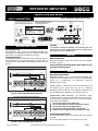
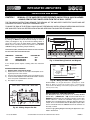
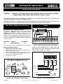
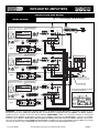
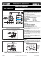
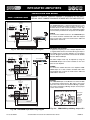
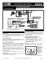
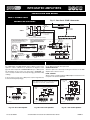
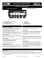
®
Manual
Integrated Amplifiers
PROFESSIONAL AUDIO & SOUND
OM 167
Installation Manual
and Operating Instructions
T3115BGM - 15 Watt RMS
T3130BGM - 30 Watt RMS
Series 3000
4 Channel - 2 Zone - VOX -MOH Phone Interface
IMPORTANT NOTE: THIS OPERATING MANUAL IS PROVIDED AS AN INSTALLATION AND
AS AN OPERATING AID. PASO SOUND PRODUCTS, INC. DOES NOT ASSUME ANY
RESPONSIBILITY AS TO ITS ACCURACY AND SHALL NOT BE LIABLE IN TORT OR CONTRACT FOR ANY DIRECT CONSEQUENTIAL OR INCIDENTAL LOSS OR DAMAGE ARISING
FROM THE INSTALLATION, USE OR INABILITY TO USE THIS PRODUCT.
CAUTION !
TO REDUCE THE RISK OF FIRE OR ELECTRIC
SHOCK DO NOT EXPOSE THIS APPLIANCE TO
WATER, RAIN OR MOISTURE
Innovation through technology since 1931
© copyright Paso Sound Products, Inc. 2005
Specifications are subject to change without notice
REV. 4.0
®
INTEGRATED AMPLIFIERS
PROFESSIONAL AUDIO & SOUND
DESCRIPTION AND APPLICATIONS
SPECIFICATIONS
T3115 Power Output:
T3130 Power Output:
Distortion:
Frequency Response:
Inputs:
Input 1
Input 2
Input 3
Input 4
Sensitivity & Z:
Input 1
Input 2
Input 3
Input 4
Hum & Noise:
Telephone Input:
Music on Hold Output:
Zone 2 Output:
Output Impedance:
Controls:
Front Panel:
4 Channel Inputs - 2 Zone Outputs
Wide Frequency Response
Very Low Distortion
Balanced Microphone Input
Phantom Power on MIC Input with Selector
Transformer Balanced Phone Paging Input
Telephone Input Level Control
Auxiliary Input With Stereo Summing
Auxiliary Input Attenuator
Balanced Program Input
Independent Input Controls
Bass and Treble Controls
VOX - Voice Activated Muting
Music on Hold Amplifier
MOH Amplifier Source Selector
Power Consumption:
AC Accessory Outlet:
Terminations:
Housing Finish:
Dimensions:
T3115 = 570 VA, T3130 = 600 VA
500 W Max. Unswitched
Screw Terminals, RCA Jacks
Black
10.5"W., 9.5"D., 3.5"H. (267X242X89 mm)
Net Weight:
T3115 = 8 Lbs (3.7 Kg)
T3130 = 11 Lbs (5.0 Kg)
Muting/Unmuting:
Zone 2, 1 Watt - 8 ohm Output
with Separate Control
AC Accessory Outlet
8 ohm, 25 Volt & 70 Volt
Output Impedance
Rack Mounting with Optional Kit
UL 6500 Listed (US - CANADA)
UNPACKING
Mic=1 Mv - 250 ohm balanced
Tel=100 Mv - 600 ohm balanced
Aux=100 Mv - 47K ohm
Prog.=1 Volt - 10K ohm balanced
Mic -70 db, Aux/Pgm -75 db
600 ohm Transformer balanced
600 ohm-1 Volt Transf. balanced
1 Watt-8 ohm
8 ohm, 25 Volt and 70 Volt line
Rack Mounting:
Power Requirement:
Phantom Power:
MOH Source:
Tone Control Action:
VOX:
600 ohm and 8 ohm 1 Watt
Microphone Balanced
Telephone Transformer Balanced
Auxiliary
Program Balanced
MIC Volume, AUX Volume,
PROG Volume, Bass, Treble
PHONE Level, AUX Attenuator,
MOH & ZONE 2 Level Control
On MIC Input w/internal jumper
AUX or PROG w/internal jumper
+/-10 db at 100 Hz and 10 K hz
Voice Activated Muting
MIC/PHONE mutes AUX/PROG
Mutes or Unmutes
MIC/AUX/PROG
Optional Rack Kit
117 Volt, 50-60 Hz
Rear Panel
Direct Muting or Unmuting
15 Watt RMS
30 Watt RMS
Less than 0.5% THD
20 - 20,000 Hz ± 1 db
ACCESSORIES
Immediately upon receipt of the amplifier, inspect the unit
and shipping container for indications of improper handling
or in transit damage. The equipment was carefully inspected and tested before leaving the factory. Notify the
Transportation Company immediately if any damage is
found. ONLY THE CONSIGNEE CAN FILE A CLAIM WITH
THE CARRIER FOR DAMAGE DURING SHIPMENT. Be
sure to save the carton and packing material as evidence of
damage for the shipper inspection. DO NOT SHIP the unit
back to the factory unless authorized by the factory.
27/3500 - Standard 19” Rack Mounting Kit. Black finish.
Complete with hardware
IN TRANSIT DAMAGES ARE NOT COVERED BY THE
PASO WARRANTY.
PAGE 2
© copyright Paso Sound Products, Inc. 2005
Specifications are subject to change without notice
T3115/3130/3160BGM
®
INTEGRATED AMPLIFIERS
PROFESSIONAL AUDIO & SOUND
IMPORTANT SAFETY INSTRUCTIONS
READ BEFORE OPERATING
READ BEFORE OPERATING
BEFORE OPERATING THE AMPLIFIER, BE SURE YOU
FULLY UNDERSTAND ALL INSTRUCTIONS AND FEATURES OF THE UNIT.
outlet, consult an electrician for replacement of the
obsolete outlet.
12) Use only the attachments and accessories specified in this manual.
13) If a cart is used, use caution when moving the
cart/apparatus combination to avoid injury from tipover.
14) Unplug this apparatus during lighting storms or
when unused for long periods of time.
15) Refer all servicing to qualified service personnel.
Servicing is required when the apparatus has been
damaged in any way, such as power supply cord or
plug is damaged, liquid has been spilled or objects
have fallen into the apparatus, the apparatus has been
exposed to rain or moisture, does not operate normally, or has been dropped.
16) DO NOT replace fuses unless power cord is
removed from the AC wall outlet.
17) DO NOT install accessories unless the power
cord is removed from the AC wall outlet.
1) Read these instructions carefully.
2) Keep these instructions.
3) Heed all Warnings.
4) Follow all instructions.
5) DO NOT use this apparatus near water.
6) Clean ONLY with a damp cloth.
7) DO NOT block any of the ventilation openings.
Install in accordance with the instructions provided.
8) DO NOT install near any heat sources such as
radiators, stoves, or other apparatus (including amplifiers) that produce heat.
9) DO NOT mount amplifier into a container or a
closed unventilated closet while operating.
10) DO NOT place any object or accessory equipment
such as Tuners, Mixers, Cassette Decks, etc. on top of
the amplifier. Obstructing or closing the cabinet ventilation openings may cause overheating.
11) DO NOT defeat the safety purpose of the polarized or grounding type plug. A polarized plug has two
blades with one wider than the other. A grounding type
plug has two blades and a third grounding prong. The
wide blade and or the third prong is provided for your
safety. When the provided plug does not fit into your
TO REDUCE THE RISK OF FIRE OR
ELECTRIC SHOCK DO NOT EXPOSE
THIS APPLIANCE TO WATER, RAIN OR
MOISTURE
RACK MOUNTING
A) Procure the optional accessory Rack Mount Kit.
B) Turn amplifier up side down and remove the four rubber feet by unscrewing the four holding screws.
C) Remove three screws on each side of the amplifier holding the amplifier cover.
D) Install the rack kit brackets by using the self-tapping screws provided and the screws removed as per C.
Fig. 3 - Rack Kit Mounting
SERIES
3.
2.
.
4. 5
1.
0.
.6
.
MIC
3000
.7 3.
.8 2.
.1 9 1 .
0
.
4. 5
0.
INTEGRATED AMPLIFIER
.6
.7 3.
.8 2.
. 9 1.
.1 0
AUX
.
4. 5
0.
.6
.7
.8
.9
. 10
PROGRAM
2.
1.
0
.
.1
3.
4.
5 .BASS
.2
.3
.4
.5
+
2.
3.
1.
0
.
.1
.2
.3
.4
4.
-.
.5
5
+
TREBLE
O
POWER
3115rack mount
T3115/3130/3160BGM
SPECIFICATIONS ARE SUBJECT TO CHANGE WITHOUT NOTICE
PAGE 3
®
INTEGRATED AMPLIFIERS
PROFESSIONAL AUDIO & SOUND
FRONT PANEL CONTROLS
SERIES
4.
5.
3.
2.
1
.
0.
INTEGRATED AMPLIFIER
3000
.6
4.
5
.
MIC
4.
.6
.7 3 .
. 8 2.
.9 1 .
. 10
®
PROFESSIONAL AUDIO & SOUND
.7
.8
.9
0.
5.
1
AUX
.
0.
0.
2.
.7
.8
.9
2.
. 10
1.
.6
3.
3
.
4.
-5
. 10
PROGRAM
1.
.1
.
.
.2
.3
.4
5+
BASS
0.
2.
3
.1
.2
.3
.4
.
4.
-5
.
O
. 5+
TREBLE
POWER
3115cont
1
2
3
4
5
6
Fig. 4 - Front Panel Controls
1)
2)
3)
MICROPHONE Input Volume Control
AUX Volume Control
PROGRAM Volume Control
4)
5)
6)
Bass Control
Treble Control
On-Off Power Switch
REAR PANEL INPUTS - OUTPUTS
1
2
CAUTION; TO REDUCE THE RISK OF FIRE OR SHOCK DO NOT
EXPOSE THIS APPLIANCE TO RAIN OR MOISTURE. DO NOT
REMOVE COVER. THERE ARE NO USER SERVICEABLE PARTS
INSIDE. REFER SERVICING TO QUALIFIED SERVICE PERSONNEL.
4
ATTENTION: POUR REDUIRLES RISQUES D© INCENDIE OU
DE CHOC ELECTRIQUE, NE PAS EXPOSER A LA PLUIE OU
L©HUMIDITE, NE PAS ENLEVER LE COUVERCLE. AUCUN
REGLAGE A L©INTERIEUR. POUR REPARATION
CONSULTERUNE PERSONNE QUALIFIEE
T3115BGM
117V 60 Hz
3
6
5
7
AUX
47K ohm 200 Mv
IN PARALLEL
MOH
OUTPUT
600 ohm
1 Volt
8 OHM
1 WATT
L
TEL OUTPUT
LEVEL
MOH OUTPUT
LEVEL
AMPLIFIER
POWER RATING
SUPPLY VOLTAGE
POWER CONSUMPTION
500 W MAX.
UNSWITCHED
10K OHM
1V
CAUTION: TO REDUCE THE RISK OF FIRE,
REPLACE ONLY WITH SAMETYPE OF
FUSE.
ATTENTION: AFIN DE
REDUIR LE RISQUE
D©INCENDIE, REMPLACER
SEUL PAR UN FUSIBLE DE
MEME TYPE.
R
15 W RMS
117V 60 HZ
570 VA
COM
8
25V 70V
PROGRAM
AUX
ATTENUATOR
250 OHM
1 MV
600 OHM
100 MV
MIC
TEL
GROUND
CLASS 2 WIRING ACCEPTABLE
LINE FUSE
1.6A 250 V
UNMUTE G MUTE G COM HOT
SER. NO.
G COM HOT
G COM HOT
BALANCED
BALANCED
BALANCED
10
9
8
3115inou
15
14
13
11
12
Fig. 4A - Rear Panel Inputs and Outputs
1)
2)
3)
4)
5)
6)
7)
8)
Unswitched AC Auxiliary Socket
600 ohm MOH Output
1 Watt 8 ohm Output (2nd zone or MOH)
MOH Output Level
AUX Input
AUX Input Level Attenuator
TEL Output Level Control
Balanced Telephone Paging Input
PAGE 4
9)
10)
11)
12)
13)
14)
15)
Balanced Microphone Input
Balanced Program Input
Mute/Unmute Terminals
Speaker Output
Chassis Ground Screw
AC Line Fuse
AC Power Cord
Specifications are subject to change without notice
T3115/3130/3160BGM
®
INTEGRATED AMPLIFIERS
PROFESSIONAL AUDIO & SOUND
INSTALLATION AND WIRING
Fig. 5 Amplifier Rear Panel View
INPUT CONNECTIONS
CAUTION; TO REDUCE THE RISK OF FIRE OR SHOCK DO NOT
EXPOSE THIS APPLIANCE TO RAIN OR MOISTURE. DO NOT
REMOVE COVER. THERE ARE NO USER SERVICEABLE PARTS
INSIDE. REFER SERVICING TO QUALIFIED SERVICE PERSONNEL.
ATTENTION: POUR REDUIRLES RISQUES D© INCENDIE OU
DE CHOC ELECTRIQUE, NE PAS EXPOSER A LA PLUIE OU
L©HUMIDITE, NE PAS ENLEVER LE COUVERCLE. AUCUN
REGLAGE A L©INTERIEUR. POUR REPARATION
CONSULTERUNE PERSONNE QUALIFIEE
AUX
47K ohm 200 Mv
IN PARALLEL
MOH
T3115BGM
117V 60 Hz
600 ohm
1 Volt
L
OUTPUT
8 OHM
1 WATT
TEL OUTPUT
LEVEL
MOH OUTPUT
LEVEL
AMPLIFIER
500 W MAX.
UNSWITCHED
COM
8
25V 70V
AUX
ATTENUATOR
250 OHM
1 MV
10K OHM
1V
CAUTION: TO REDUCE THE RISK OF FIRE,
REPLACE ONLY WITH SAMETYPE OF
FUSE.
ATTENTION: AFIN DE
REDUIR LE RISQUE
D©INCENDIE, REMPLACER
SEUL PAR UN FUSIBLE DE
MEME TYPE.
R
15 W RMS
117V 60 HZ
570 VA
POWER RATING
SUPPLY VOLTAGE
POWER CONSUMPTION
PROGRAM
600 OHM
100 MV
MIC
TEL
G COM HOT
G COM HOT
BALANCED
BALANCED
GROUND
CLASS 2 WIRING ACCEPTABLE
LINE FUSE
1.6A 250 V
SER. NO.
MICROPHONE INPUT
MICROPHONE TYPE
The Microphone Input accept Low Impedance (250-600 ohm)
Microphones. The Microphone may be a balanced output type
(three wire) or an unbalanced output type (two wire).
PASO MICROPHONES
All PASO low impedance Microphones have a balanced output for
best performance. Connect the RED lead to terminal HOT, the
WHITE lead to terminal COM and the SHIELD to terminal G (see
Fig. 5A).
UNMUTE G MUTE G COM HOT
BALANCED
CAUTION
TO PREVENT POSSIBLE DAMAGE TO SPEAKERS OR THE
AMPLIFIER ALL INPUT CONNECTIONS MUST BE MADE WITH
THE AMPLIFIER OFF (POWER OFF).
WIRING
MICROPHONE INPUT
Attach the microphone leads to the terminal strip as per diagram
in Fig 5A or Fig. 5B.
DO NOT GROUND THE MICROPHONE CABLE SHIELD TO THE
CHASSIS OF THE AMPLIFIER
THREE LEADS BALANCED MICROPHONE WIRING
The microphone lead color refers to Paso Microphones only. When using
other microphone brand refer to instructions packed with the unit.
CABLE
RED
BALANCED MICROPHONE
IMPORTANT NOTE: The use of an unbalanced Microphone (two
leads) is not recommended. For best results in a PA Application
always use a Unidirectional, Low Impedance, Balanced
Microphone (three leads).
WHITE
SHIELD
MIC
PROGRAM
UNMUTE
G
MUTE
3115micbal
G
COM
MIC
HOT
G
BALANCED
COM
HOT
BALANCED
CABLE LENGTH - If the distance between the Microphone and
the Amplifier Input is greater than 15 ft (4.5 m) a Balanced
Microphone must be used. Use a two conductor shielded wire and
connect Microphone to Amplifier as per Diagram in Fig. 5A.
Fig. 5A - Rear Panel MIC Input Terminals
MICROPHONE CABLE ROUTING - The Microphone Cable
should be carefully routed. Improper Cable routing will cause spurious oscillations, regenerative noises, hum, etc. that may permanently damage the Amplifier.
Do not route cable next to power lines.
Do not route cable near or over Fluorescent Fixtures.
Do not route cable next to Speaker Wires.
Do not install cable inside Power Line Conduits.
Avoid the use of staples that may penetrate the cable.
TWO LEADS UNBALANCED MICROPHONE WIRING
The microphone lead color refers to Paso Microphones only. When
using other microphone brand refer to instructions packed with the unit.
RED
WHITE
SHIELD
MIC
MIC
PROGRAM
UNMUTE
G
3115micunbal
MUTE
G
COM
BALANCED
HOT
G
COM
BALANCED
HOT
UNBALANCED MICROPHONE
Attach the Microphone leads to the terminal strip as per diagram
in Fig 5B.
Be sure the cable length does not exceeds 15 Ft. (4.5 m).
Fig. 5B - Rear Panel MIC Input Terminals
T3115/3130/3160BGM
SPECIFICATIONS ARE SUBJECT TO CHANGE WITHOUT NOTICE
PAGE 5
®
INTEGRATED AMPLIFIERS
PROFESSIONAL AUDIO & SOUND
INSTALLATION AND WIRING
INPUT CONNECTIONS
MICROPHONE INPUT
WIRING
USING A PUSH-TO-TALK DESK BASE MICROPHONE
Microphone paging and precedence over the AUX or PROGRAM
channels may be accomplished by using a Desk Base or a
Gooseneck Microphone. Wire the Microphone output leads to the
MIC input terminals as per Fig. 6A.
MUTING: The Amplifier is equipped with two independent Muting
Circuits:
Direct Muting by shorting the MUTE Terminals
Automatic Muting with VOX - Voice Activated Muting
For additional information on the Muting operation refer to the
Muting Functions section of this Manual.
Wire the Desk Base Microphone leads to the Microphone Input
terminal strip as per diagram in Fig 6A. Check Microphone instructions and connect HOT LEAD (B) to Terminal HOT, COMMON
LEAD (A) to Terminal COM and SHIELD LEAD to Terminal G.
DO NOT GROUND THE MICROPHONE CABLE SHIELD TO THE
CHASSIS OF THE AMPLIFIER
DESK BASE/GOOSENECK MICROPHONE WITH MUTING SWITCH
MICROPHONE OUTPUT LEVEL CONTROL IS LOCATED ON THE FRONT PANEL
Push to Talk Key
MIC
SHIELD
MUTING SWITCH
MIC
A
B
b50side
PROGRAM
UNMUTE
G
MUTE
G
COM
MIC
HOT
G
TEL
COM
HOT
G
COM
HOT
micbas03
Fig. 6A - Rear Panel MIC Input Terminals
Fig. 6C - Desk Base Microphone
CONNECTING TO THE TELEPHONE PAGING SYSTEM
DMS
OUTPUT LEVEL
TM
DIGITAL MUSIC AMPLIFIER
TEL
PEAK
DIGITAL MUSIC SERIES
PROFESSIONAL AUDIO & SOUND
POWER
0
10
INPUT 1
0
10
INPUT 2
0
10
INPUT 3
0
10
INPUT 4/AUX 1
0
10
0
INPUT 5/AUX 2
10
-10
MODULE
+10
-10
BASS
O
+10
TREBLE
DMS Amplifier
KSU
Key Service Unit
TEL OUTPUT
LEVEL
TELEPHONE PAGING LEVEL CONTROL
TIP
RING
R
PROGRAM
teleinp03
G
MUTE
G
COM
BALANCED
MIC
HOT
G
COM
T
TEL
HOT
BALANCED
G
COM
DO NOT GROUND THE TIP OR RING WIRE TO THE CHASSIS
OF THE AMPLIFIER
OUTPUT LEVEL CONTROL - An Output Level Control is provided
on the rear panel. After wiring adjust control for the desired output
level.
HOT
BALANCED
Fig. 6B - Rear Panel TEL Input Terminals
PAGE 6
WIRING - The Amplifier is interface ready for the Telephone line in
applications requiring paging from the telephone system. The
Telephone line Paging Output (Tip and Ring) can be directly connected to the TEL input and to the HOT and COM as shown in the
wiring diagram Fig. 6B.
CABLE - Use a two conductor twisted wire.
TEL
UNMUTE
telpagin
PAGING FROM THE TELEPHONE SYSTEM
TELEPHONE PAGING INPUT
Telephone
System KSU
Telephone
VOICE ACTIVATED MUTING (VOX) - Muting of the AUX or PROGRAM channels (music muting) during Paging is automatic via the
Voice Activated Muting System. No contact closure for the Muting
Circuit is required from the Telephone system. For additional information on the Muting operation refer to the Muting Functions section of this Manual.
Specifications are subject to change without notice
T3115/3130/3160BGM
®
INTEGRATED AMPLIFIERS
PROFESSIONAL AUDIO & SOUND
INSTALLATION AND WIRING
CAUTION !
REMOVAL OF THE AMPLIFIER COVER PRESENTS AN ELECTRICAL SHOCK HAZARD
ALWAYS REMOVE THE POWER CORD FROM THE AC WALL OUTLET
THE FOLLOWING INSTRUCTIONS REQUIRE THE REMOVAL OF THE AMPLIFIER PROTECTIVE COVER AND ARE
PROVIDED FOR USE BY QUALIFIED PERSONNEL ONLY.
TO AVOID THE RISK OF ELECTRICAL SHOCK DO NOT PERFORM ANY INSTALLATION OR SERVICING UNLESS YOU
ARE QUALIFIED TO DO SO. REFER INSTALLATION OR SERVICING TO QUALIFIED PERSONNEL.
INPUT CONNECTIONS
CONDENSER AND ELECTRET MICROPHONES
WIRING
CONDENSER AND ELECTRET TYPE MICROPHONES
Condenser and Electret Microphones require a DC Operating
Voltage. Paso Amplifiers provide this operating voltage or Phantom
Power selectively on the Microphone Input.
CONDENSER/ELECTRET MICROPHONE
Carefully follow the wiring instruction packed with the Microphone
used. Attach the microphone leads to the terminal strip as per diagram in Fig 7.
Prior to selecting the Condenser or Electret Microphone be sure
that the Operating Voltage and Output Impedance of the device
match the Input characteristics of the Amplifier listed below.
Phantom Power
Input Impedance
= 16 Volt DC
= 250 to 600 ohm
ACCESS TO PHANTOM POWER SELECTOR
1) Remove Power Cord from AC Outlet.
2) Remove the three screws on each side of the Amplifier and
the three screws located on the Rear Panel Top securing the
Top Cover to the Chassis.
3) Lift Cover and carefully slide Cover out towards the rear.
4) Locate the Preamplifier Printed Board No. 3130-2 attached
to the rear panel and behind the Inputs Terminal Strip.
DO NOT GROUND THE MICROPHONE CABLE SHIELD TO THE
CHASSIS OF THE AMPLIFIER
BALANCED CONDENSER/ELECTRET MICROPHONE WIRING
The diagram indicates the Phantom Power Voltage and Polarity available at
the Input Terminals when the Phantom Power is activated
MICROPHONE
CONDENSER
ELECTRET
SHIELD
MIC
PROGRAM
UNMUTE
G
3115micbal05
MICROPHONE INPUT PHANTOM POWER
AMPLIFIER REAR PANEL
MUTE
G
COM
BALANCED
HOT
0
+16V
+16V
G
COM
HOT
BALANCED
Fig. 7 - Rear Panel MIC Input Terminals
PHANTOM POWER SELECTOR
PHANTOM POWER SELECTOR JUMPER
By following the Preamplifier Printed Board layout as
shown on Fig. 7A locate the Selector Jumper marked
PHANTOM.
The Jumper Socket is marked as follows:
JP4
= ON - OFF - PHANTOM
To turn the Phantom Power On, re-position the
Jumper to the ON POSITION (JP 4).
To change the Selector position lift the Mini Shorting
Plug out of the socket pins and re-position as desired.
Make sure the Mini Plug is lined up with the socket
pins.
Fig. 7A - Preamplifier PCB Top View
T3115/3130/3160BGM
SPECIFICATIONS ARE SUBJECT TO CHANGE WITHOUT NOTICE
PAGE 7
®
INTEGRATED AMPLIFIERS
PROFESSIONAL AUDIO & SOUND
INSTALLATION AND WIRING
MUTING FUNCTIONS
VOX - VOICE ACTIVATED MUTING
MUTING FUNCTIONS
VOX - VOICE ACTIVATED MUTING - The Amplifier is equipped
with a noiseless, fast acting Logic Muting Function. When a signal
is present at the MICROPHONE or TELEPHONE Input, either
from a Microphone or a Telephone Paging source, the Muting
Function is activated muting the source present at the AUX Input
and as well as the source present at the PROGRAM input if selectively activated. Once the Signal (paging) is terminated the program is automatically restored on all muted inputs.
The Amplifier provides several levels of Muting functions:
MICROPHONE
TELEPHONE
AUXILIARY
PROGRAM
Can be selectively Muted by internal selector
This input is never Muted
Can be selectively Muted by internal selector
Can be selectively Muted by internal selector
MUTING JUMPERS ADDRESS
Several Jumpers are provided to set the Muting functions:
FOR THE VOX ATTACK AND DECAY TIMING REFER TO THE
FIG. 9B DIAGRAM.
ACCESS TO MUTING SELECTORS
FOLLOW DIRECTIONS AS PER DIRECT MUTING FUNCTION.
VOX SENSITIVITY CONTROL
JUMPER NO.
FUNCTION
JP 1
MICROPHONE Mute ON - OFF
JP 2
AUXILIARY Mute ON - OFF
JP 3
PROGRAM Mute ON - OFF
NOTE: The Microphone Input is provided with a unique MUTE
and UNMUTE function. See the Mute/Unmute operation instructions in the appropriate section in this Manual.
The VOX Sensitivity Intervention threshold is adjusted at the factory for best performance and does not require re-touching under normal circumstances. Should the Trimmer pre-setting require adjustment follow the instructions listed below.
VOX SENSITIVITY ADJUSTMENT
VOX SENSITIVITY TRIMMER
3130 - 1
CAUTION: PRIOR TO PERFORMING THIS
OPERATION BE SURE TO FOLLOW THE
SAFETY NOTES REFERRING TO THE
REMOVAL OF THE AMPLIFIER COVER.
AUTOMATIC PRECEDENCE THRESHOLD
The VOX Trimmer VR 9 sets the sensitivity level at which
point the VOX is engaged during paging. The VOX
Trimmer VR9 is located on the Main Printed Circuit
Board (see Fig.89).
JP3
JP2
ON
ON
VR9
VOX
JP1
VOX
OFF
CAUTION: Procure a miniature screwdriver having a tip
NO WIDER than 3/16” (3 mm). A larger tip screwdriver
can damage the trimmer.
ON
OFF
OFF
SELECTOR JUMPERS
MIC
VOLUME
AUX
VOLUME
PROGRAM
VOLUME
Fig.8 - Main Amplifier PCB - VOX - MUTING Section - Top View
PAGE 8
Specifications are subject to change without notice
1) Turn all Input Controls to 0.
2) Turn Trimmer counterclockwise until it stops.
3) Connect a Paging Source (Microphone or Telephone)
to the respective Input Terminals (For connection details
refer to the appropriate section in this Manual).
4) While talking from the Paging Source (Microphone or
Telephone) rotate the MIC (Front Panel) or TEL (Rear
panel) Volume Control until the desired output level is
achieved.
5) Connect a Music Source to the AUX 1 Input and
rotate the AUX 1/CD Volume Control on the front panel
until the desired output level is achieved.
6) While talking from the Paging Source (Microphone or
Telephone) turn the Trimmer slowly clockwise until the
Program (music) is cut-off (Muting activated).
VOX DEFEAT INSTRUCTIONS
In applications requiring the VOX to be
inoperative rotate the VOX TRIMMER VR 9
fully counterclockwise. In this position the
VOX is inoperative.
T3115/3130/3160BGM
®
INTEGRATED AMPLIFIERS
PROFESSIONAL AUDIO & SOUND
INSTALLATION AND WIRING
CAUTION !
REMOVAL OF THE AMPLIFIER COVER PRESENTS AN ELECTRICAL SHOCK HAZARD
ALWAYS REMOVE THE POWER CORD FROM THE AC WALL OUTLET
THE FOLLOWING INSTRUCTIONS REQUIRE THE REMOVAL OF THE AMPLIFIER PROTECTIVE COVER AND ARE
PROVIDED FOR USE BY QUALIFIED PERSONNEL ONLY.
TO AVOID THE RISK OF ELECTRICAL SHOCK DO NOT PERFORM ANY INSTALLATION OR SERVICING UNLESS YOU
ARE QUALIFIED TO DO SO. REFER INSTALLATION OR SERVICING TO QUALIFIED PERSONNEL.
MUTING FUNCTIONS
WIRING
DIRECT MUTING
MICROPHONE WITH DIRECT MUTING SWITCH
DIRECT MUTING - Program (Music) Muting may be accomplished
by shorting the MUTE and the G Terminals through an external
switch (see Diagram in Fig. 9). Each time the Muting Switch is
closed the source from the AUX INPUT and the PROGRAM
INPUT may be selectively muted in accordance to the MUTING
JUMPERS setting (See Muting Jumpers Address).
MIC
SHIELD
MUTING SWITCH
PROGRAM
MIC
TEL
THE MUTING (VOX) JUMPERS ARE PRESET AT THE FACTORY
AS PER TABLE AND DIAGRAM BELOW:
JUMPER NO.
FUNCTION
POSITION SET
JP 1
JP 2
JP 3
MICROPHONE Mute
AUXILIARY Mute
PROGRAM Mute
OFF
ON
ON
If the Jumpers preset requires resetting follow the instruction
below.
ACCESS TO MUTING JUMPERS
1) Remove Power Cord from AC Outlet.
2) Remove the four screws on each side of the Amplifier securing the Top Cover to the Chassis.
3) Lift Cover and carefully and slide Cover out towards the rear.
4) Locate the Main Amplifier Printed Board No.3130-1 attached
to the front panel and behind the Controls.
5) Set Jumpers as required.
JP1= OFF - JP2= ON - JP3= ON
UNMUTE
G
MUTE
G
COM
HOT
G
COM
HOT
G
COM
HOT
3115mutswit03
Fig. 9 - Direct Muting Terminals and Diagram
Mute
terminals
shorted
Signal
Level
Program
Attenuation
50 db
2-3
sec.
Program
gradually
restored
Mute terminals
opened
time
mutfunct
Fig. 9B - Muting Function Timing Diagram
MUTING TIMING - The Program Attenuation is preadjusted for -50 db.
When the Muting is activated the Program Source is instantaneously
turned-off. When the Muting is turned off the program (music) is gradually
restored (2-3 seconds).
JP1
VOX
JP2
ON
ON
VR9
VOX
OFF
MUTING/UNMUTING
JP3
ON
OFF
OFF
Fig. 9C - Muting Jumpers Pre-Set
MICROPHONE INPUT UNMUTING FUNCTION
The Microphone Input can be preset to be normally MUTED
(INPUT OFF) - (JUMPER JP1 - ON) and turned ON when the
UNMUTE and G Terminals are shorted by a Switch Contact. This
function allows for a multi zone installation using two or more
Amplifiers and a single Microphone and Zone Switches. When the
Jumper JP1 is set to the ON Position the Microphone Input is OFF
and it is turned ON when the UNMUTE and the G terminals are
closed by a switch.
A 3 Zone Paging Wiring Diagram illustrating this Application is provided in this Manual.
T3115/3130/3160BGM
SPECIFICATIONS ARE SUBJECT TO CHANGE WITHOUT NOTICE
PAGE 9
®
INTEGRATED AMPLIFIERS
PROFESSIONAL AUDIO & SOUND
INSTALLATION AND WIRING
CAUTION !
REMOVAL OF THE AMPLIFIER COVER PRESENTS AN ELECTRICAL SHOCK HAZARD
ALWAYS REMOVE THE POWER CORD FROM THE AC WALL OUTLET
THE FOLLOWING INSTRUCTIONS REQUIRE THE REMOVAL OF THE AMPLIFIER PROTECTIVE COVER AND ARE
PROVIDED FOR USE BY QUALIFIED PERSONNEL ONLY.
TO AVOID THE RISK OF ELECTRICAL SHOCK DO NOT PERFORM ANY INSTALLATION OR SERVICING UNLESS YOU
ARE QUALIFIED TO DO SO. REFER INSTALLATION OR SERVICING TO QUALIFIED PERSONNEL.
MIC INPUT UNMUTING FUNCTION
WIRING
DIRECT MUTING/UNMUTING
MICROPHONE WITH DIRECT UNMUTING SWITCH
MICROPHONE INPUT UNMUTING FUNCTION
The Microphone Input can be preset to be normally MUTED
(INPUT OFF) - (JUMPER JP1 - ON) and turned ON when the
UNMUTE and G Terminals are shorted by a Switch Contact. This
function allows for a multi zone installation using two or more
Amplifiers and a single Microphone and Zone Switches. When the
Jumper JP1 is set to the ON Position the Microphone Input is OFF
and it is turned ON when the UNMUTE and the G terminals are
closed by a switch.
JUMPER NO.
JP 1
FUNCTION
POSITION SET
MICROPHONE Mute
ON
MIC
SHIELD
UNMUTING SWITCH
PROGRAM
UNMUTE
G
MUTE
G
COM
MIC
HOT
G
TEL
COM
HOT
G
COM
HOT
3115unmutswit00
If the Jumper preset requires resetting follow the instruction below.
Fig. 10 - Direct Unmuting Terminals and Diagram
ACCESS TO MUTING JUMPERS
1) Remove Power Cord from AC Outlet.
2) Remove the four screws on each side of the Amplifier securing the Top Cover to the Chassis.
3) Lift Cover and carefully slide Cover out towards the rear.
4) Locate the Main Amplifier Printed Board No.3130-1 attached
to the front panel and behind the Controls.
5) Set Jumpers as required.
A typical 3 Zone Switching Panel is shown below. Use
SPDT Momentary Contact Switches. See complete 3 Zone
Wiring Diagram provided in this Manual.
ZONE PAGING SELECTORS
MIC MUTE JUMPER JP1= ON
1
2
3
ZONE 1
ZONE 2
ZONE3
JP3
TO AMP 2
JP2
TO AMP 3
ON
ON
JP1
VR9
VOX
OFF
TO AMP 1
VOX
ON
OFF
OFF
TO MIC INPUT
PAGING MICROPHONE
3 Zone Panel
Fig. 10B - MIC Input Muting Jumper Setting
PAGE 10
Fig. 10C - 3 Zone Switching Panel
Specifications are subject to change without notice
T3115/3130/3160BGM
®
INTEGRATED AMPLIFIERS
PROFESSIONAL AUDIO & SOUND
INSTALLATION AND WIRING
Fig. 11 - 3 Zone Paging and Music System
WIRING DIAGRAM
CAUTION; TO REDUCE THE RISK OF FIRE OR SHOCK DO
NOT EXPOSE THIS APPLIANCE TO RAIN OR MOISTURE. DO
NOT REMOVE COVER. THERE ARE NO USER SERVICEABLE
PARTS INSIDE. REFER SERVICING TO QUALIFIED SERVICE
PERSONNEL.
ATTENTION: POUR REDUIRLES RISQUES D© INCENDIE
OU DE CHOC ELECTRIQUE, NE PAS EXPOSER A LA
PLUIE OU L©HUMIDITE, NE PAS ENLEVER LE
COUVERCLE. AUCUN REGLAGE A L©INTERIEUR.
POUR REPARATION CONSULTERUNE PERSONNE
QUALIFIEE
MOH
T3115BGM
117V 60 Hz
MUSIC OUTPUT
AUX
47K ohm 200 Mv
IN PARALLEL
L
OUTPUT
600 ohm 8 OHM
1 Volt
1 WATT
TEL OUTPUT
LEVEL
MOH OUTPUT
LEVEL
SATELLITE RECEIVER
AMPLIFIER
POWER RATING
SUPPLY VOLTAGE
POWER CONSUMPTION
CAUTION: TO REDUCE THE RISK OF
FIRE, REPLACE ONLY WITH
SAMETYPE OF FUSE.
ATTENTION: AFIN DE
REDUIR LE RISQUE
D©INCENDIE, REMPLACER
SEUL PAR UN FUSIBLE
DE MEME TYPE.
COM
8
25V 70V
AUX
ATTENUATOR
600 OHM
100 MV
10K OHM
1V
250 OHM
1 MV
PROGRAM
MIC
TEL
G COM HOT
G COM HOT
BALANCED
BALANCED
GROUND
CLASS 2 WIRING ACCEPTABLE
LINE FUSE
1.6A 250 V
UNMUTE
G
MUTE G COM HOT
BALANCED
SER. NO.
MUSIC SOURCE LINE
500 W MAX.
UNSWITCHED
R
15 W RMS
117V 60 HZ
570 VA
ZONE 1
25V/70V Speaker
CAUTION; TO REDUCE THE RISK OF FIRE OR SHOCK DO
NOT EXPOSE THIS APPLIANCE TO RAIN OR MOISTURE. DO
NOT REMOVE COVER. THERE ARE NO USER SERVICEABLE
PARTS INSIDE. REFER SERVICING TO QUALIFIED SERVICE
PERSONNEL.
25V/70V Speaker
25V/70V Speaker
ATTENTION: POUR REDUIRLES RISQUES D© INCENDIE
OU DE CHOC ELECTRIQUE, NE PAS EXPOSER A LA
PLUIE OU L©HUMIDITE, NE PAS ENLEVER LE
COUVERCLE. AUCUN REGLAGE A L©INTERIEUR.
POUR REPARATION CONSULTERUNE PERSONNE
QUALIFIEE
AUX
47K ohm 200 Mv
IN PARALLEL
ZONE PAGING SELECTORS
MOH
T3115BGM
117V 60 Hz
L
OUTPUT
600 ohm 8 OHM
1 Volt
1 WATT
TEL OUTPUT
LEVEL
MOH OUTPUT
LEVEL
1
2
3
ZONE 1
ZONE 2
ZONE3
AMPLIFIER
POWER RATING
SUPPLY VOLTAGE
POWER CONSUMPTION
500 W MAX.
UNSWITCHED
CAUTION: TO REDUCE THE RISK OF
FIRE, REPLACE ONLY WITH
SAMETYPE OF FUSE.
ATTENTION: AFIN DE
REDUIR LE RISQUE
D©INCENDIE, REMPLACER
SEUL PAR UN FUSIBLE
DE MEME TYPE.
R
15 W RMS
117V 60 HZ
570 VA
COM
8
25V 70V
AUX
ATTENUATOR
600 OHM
100 MV
10K OHM
1V
250 OHM
1 MV
PROGRAM
MIC
TEL
G COM HOT
G COM HOT
BALANCED
BALANCED
GROUND
CLASS 2 WIRING ACCEPTABLE
LINE FUSE
1.6A 250 V
UNMUTE
G
MUTE G COM HOT
BALANCED
SER. NO.
HOT
COMMON
ZONE 2
GROUND (SHIELD)
CAUTION; TO REDUCE THE RISK OF FIRE OR SHOCK DO
NOT EXPOSE THIS APPLIANCE TO RAIN OR MOISTURE. DO
NOT REMOVE COVER. THERE ARE NO USER SERVICEABLE
PARTS INSIDE. REFER SERVICING TO QUALIFIED SERVICE
PERSONNEL.
25V/70V Speaker
25V/70V Speaker
ATTENTION: POUR REDUIRLES RISQUES D© INCENDIE
OU DE CHOC ELECTRIQUE, NE PAS EXPOSER A LA
PLUIE OU L©HUMIDITE, NE PAS ENLEVER LE
COUVERCLE. AUCUN REGLAGE A L©INTERIEUR.
POUR REPARATION CONSULTERUNE PERSONNE
QUALIFIEE
AUX
47K ohm 200 Mv
IN PARALLEL
MOH
T3115BGM
117V 60 Hz
L
OUTPUT
600 ohm 8 OHM
1 Volt
1 WATT
PAGING MICROPHONE
MUSIC SOURCE LINE
25V/70V Speaker
Paging Microphone should be
Unswitched and always ON
MICROPHONE WIRE
2 Conductor Shielded
TEL OUTPUT
LEVEL
MOH OUTPUT
LEVEL
AMPLIFIER
POWER RATING
SUPPLY VOLTAGE
POWER CONSUMPTION
COM
8
25V 70V
10K OHM
1V
250 OHM
1 MV
PROGRAM
MIC
600 OHM
100 MV
MUTING SELECTOR JUMPERS SETTING ON
ALL THREE ZONE AMPLIFIERS
TEL
JP1= ON - JP2= ON - JP3= ON
LINE FUSE
1.6A 250 V
CLASS 2 WIRING ACCEPTABLE
UNMUTE
G
MUTE G COM HOT
BALANCED
SER. NO.
G COM HOT
G COM HOT
BALANCED
BALANCED
VOX
VR9
VOX
ZONE 3
OFF
GROUND
JP3
JP2
ON
ON
ATTENTION: AFIN DE
REDUIR LE RISQUE
D©INCENDIE, REMPLACER
SEUL PAR UN FUSIBLE
DE MEME TYPE.
AUX
ATTENUATOR
JP1
500 W MAX.
UNSWITCHED
CAUTION: TO REDUCE THE RISK OF
FIRE, REPLACE ONLY WITH
SAMETYPE OF FUSE.
R
15 W RMS
117V 60 HZ
570 VA
ON
25V/70V Speaker
25V/70V Speaker
OFF
OFF
25V/70V Speaker
3115
V o x J umpers
OPERATION - A 3 Zone Paging Wiring Diagram Application is provided.The Paging Microphone is connected in parallel to all the
Microphone Inputs. Three Independent SPDT Switches are provided for the Paging Zone Selection. MUSIC - The MUSIC SOURCE
(Satellite receiver) is cascade connected to all three Amplifiers. ZONE PAGING - When one or more Zone Switches are activated the
UNMUTE Function OPENS the Microphone Channel on the Amplifier selected and the MICROPHONE is active for the PAGING.
Simultaneously the MUSIC is MUTED ONLY ON THE ZONE (OR ZONES) SELECTED. Independent MUSIC SOURCE may be provided to each of the Amplifiers if required. MOH - MUSIC ON HOLD is available from each of the Amplifiers used. The MOH source maybe
selected from either the AUX or PROGRAM Input and is immune to Paging or the MUTE/UNMUTE Function.
T3115/3130/3160BGM
SPECIFICATIONS ARE SUBJECT TO CHANGE WITHOUT NOTICE
PAGE 11
®
INTEGRATED AMPLIFIERS
PROFESSIONAL AUDIO & SOUND
INSTALLATION AND WIRING
CAUTION: TO PREVENT POSSIBLE DAMAGE TO SPEAKERS OR THE AMPLIFIER ALL INPUT CONNECTIONS MUST BE MADE WITH THE AMPLIFIER OFF.
INPUT CONNECTIONS
AUX INPUT
AUXILIARY INPUT
The AUX input is provided for high level program source. The output from a Satellite Receiver Tuner, Tape Cassette Deck, CD
Player or other high level program source may be directly connected to this input.
MUSIC OUTPUT
L
R
L
R
AUX INPUT SENSITIVITY ATTENUATOR
The AUX Input is equipped with a Sensitivity Attenuator that
allows the interface of the AUX Input with Devices having a wide
range of Output Levels.
AUX
47K ohm 200 Mv
IN PARALLEL
SATELLITE RECEIVER
MOH
600 ohm
1 Volt
L
OUTPUT
8 OHM
1 WATT
TEL OUTPUT
LEVEL
MOH OUTPUT
LEVEL
paso
AM/FM TUNER
R
AUX
ATTENUATOR
TRACK
01
600 OHM
100 MV
250 OHM
1 MV
10K OHM
1V
TYPICAL OUTPUT LEVEL OF MUSIC DEVICES:
Satellite Receivers
= 1 to 5 Volt
Digital Tuners/Receivers
= 100 to 300 Mv
CD Players/Changers
= 2 to 3 Volt
Tape Decks
= 500 to 700 Mv
CD PLAYER
PROGRAM
MIC
TEL
CD
UNMUTE G MUTE G COM HOT
G COM HOT
G COM HOT
BALANCED
BALANCED
TAPE DECK
BALANCED
3115 Aux
Fig. 12 - Rear Panel AUX Input Diagram
Screwdriver Adjust
3115 Aux Att
AUX
47K ohm 200 Mv
IN PARALLEL
MOH
L
OUTPUT
600 ohm
1 Volt
8 OHM
1 WATT
TEL OUTPUT
LEVEL
MOH OUTPUT
LEVEL
R
AUX
ATTENUATOR
600 OHM
100 MV
250 OHM
1 MV
10K OHM
1V
PROGRAM
UNMUTE G MUTE G COM HOT
BALANCED
MIC
TEL
G COM HOT
G COM HOT
BALANCED
BALANCED
SETTING THE AUX INPUT ATTENUATOR
Connect a Music Source to the Amplifier.
Turn Attenuator (rear panel) fully counterclockwise.
Turn AUX Front Panel Control to about 2 o’ clock.
Switch Amplifier and Music Source ON.
Turn rear panel Attenuator Control clockwise slowly until desired
Output Level is achieved.
Adjust AUX Front Panel Level Control Up-Down as desired.
STEREO SUMMING
Since most Music Source Devices provide a Stereo Output the
Amplifier is equipped with two Jacks for the AUX Input (L and R).
The two Inputs are internally buffered and electronically mixed to
Mono. This system ensures that the Music Device is properly
loaded and that the Stereo Signals are correctly summed (L+R) to
Mono without distortion.
CABLE
To connect the music source devices to the AUX Input use two single conductor shielded audio cable terminated in a single prong
phono plug on both ends.
AUXILIARY INPUT MUTING
Fig. 12B - Rear Panel AUX Input Sensitivity Attenuator
MUSIC OUTPUT
L
By adjusting the Input Sensitivity to the level that matches the
device used the correct interface with the Amplifier is achieved
resulting in lower overall distortion and better frequency response
characteristics.
R
MUTING
The AUX Input can be Muted or not when the VOX is activated by Paging from the MIC Input or the Phone Input.
The same occurs when the Direct Muting is applied. For
location and Setting of Muting Jumpers see the proper section in this manual.
3115 St Sum
AUX
47K ohm 200 Mv
IN PARALLEL
8 OHM
1 WATT
R
10K OHM
1V
Diagram shows
AUX Muting ON.
TEL OUTPUT
LEVEL
MOH OUTPUT
LEVEL
PROGRAM
AUX MUTE JUMPER JP2= ON
VOX
AUX
ATTENUATOR
250 OHM
1 MV
VR9
VOX
600 OHM
100 MV
MIC
TEL
G COM HOT
G COM HOT
BALANCED
BALANCED
OFF
600 ohm
1 Volt
L
JP3
JP2
ON
ON
OUTPUT
JP1
MOH
ON
UNMUTE G MUTE G COM HOT
BALANCED
OFF
AUX Muting can
be turned OFF
by moving JP2
Jumper to the
OFF Position
OFF
3115 AUX Jumper 00
Fig. 12C - Rear Panel AUX Stereo Summing Inputs
PAGE 12
Fig. 12D - AUX Input Muting Jumper JP 2
Specifications are subject to change without notice
T3115/3130/3160BGM
®
INTEGRATED AMPLIFIERS
PROFESSIONAL AUDIO & SOUND
INSTALLATION AND WIRING
INPUT CONNECTIONS
CAUTION: TO PREVENT POSSIBLE DAMAGE TO SPEAKERS OR THE AMPLIFIER ALL INPUT CONNECTIONS MUST BE MADE WITH THE AMPLIFIER OFF.
PROGRAM INPUT
AUX
47K ohm 200 Mv
IN PARALLEL
MOH
L
OUTPUT
600 ohm
1 Volt
8 OHM
1 WATT
TEL OUTPUT
LEVEL
MOH OUTPUT
LEVEL
R
AUX
ATTENUATOR
250 OHM
1 MV
10K OHM
1V
PROGRAM
PROGRAM INPUT
The PROGRAM Input is a balanced high level input (1 Volt
Sensitivity) provided specifically for direct connection to a
Satellite Receiver with a balanced Output or other high
level Balanced Program Source. An independent Output
Level Control is provided on the front panel of the Amplifier.
600 OHM
100 MV
MIC
TEL
G COM HOT
G COM HOT
BALANCED
BALANCED
G
COM HOT
SHIELD
BALANCED
3115 Program
SHIELD
SATELLITE RECEIVER
UNMUTE G MUTE
MUSIC OUTPUT
Balanced
CABLE
To connect the Satellite Receiver to the PROGRAM Input
use a dual conductor shielded audio cable with stripped
wires on both ends. Connect the audio leads to HOT and
COM and the shield to G.
NETWORKING
Fig. 13 - Rear Panel PROGRAM Input Diagram
AUX
47K ohm 200 Mv
IN PARALLEL
OUTPUT
8 OHM
1 WATT
L
TEL OUTPUT
LEVEL
MOH OUTPUT
LEVEL
R
PROGRAM
UNMUTE G MUTE
G
AUX
ATTENUATOR
250 OHM
1 MV
10K OHM
1V
COM HOT
600 OHM
100 MV
MIC
TEL
G COM HOT
G COM HOT
BALANCED
BALANCED
SHIELD
BALANCED
3115 Network
SATELLITE RECEIVER
SHIELD
MOH
600 ohm
1 Volt
MUSIC OUTPUT
Balanced
NETWORK APPLICATION
In applications requiring the use of multiple Amplifiers with
a single Satellite Receiver, the Balanced Program Input of
the Amplifier may be used. The Amplifiers are cascaded as
shown in Diagram 13B and then connected to the Satellite
Receiver Balanced Output.
The Music Output Level may be adjusted by using the
PROGRAM Output Level Control available on the front
panel of each Amplifier.
WIRING
To connect the Satellite Receiver to the Amplifiers PROGRAM Input use a dual conductor shielded audio cable
with stripped wires. Connect the audio leads to HOT and
COM and the shield to G.
AMPLIFIER 1
PROGRAM INPUT MUTING
AUX
47K ohm 200 Mv
IN PARALLEL
L
8 OHM
1 WATT
TEL OUTPUT
LEVEL
MOH OUTPUT
LEVEL
R
10K OHM
1V
PROGRAM
AUX
ATTENUATOR
250 OHM
1 MV
600 OHM
100 MV
MIC
TEL
G COM HOT
G COM HOT
PROGRAM MUTE JUMPER JP3= ON
Diagram shows
the PROGRAM
Muting ON.
G
COM HOT
SHIELD
BALANCED
BALANCED
VR9
VOX
BALANCED
Fig. 13B - PROGRAM Input Networking Diagram
JP3
JP2
AMPLIFIER 2
TO NEXT AMPLIFIER
T3115/3130/3160BGM
JP1
VOX
UNMUTE G MUTE
OFF
OUTPUT
ON
ON
MOH
600 ohm
1 Volt
MUTING
The PROGRAM Input can be Muted or not when the VOX
is activated by Paging from the MIC Input or the Phone
Input. The same occurs when the Direct Muting is applied.
For location and Setting of Muting Jumpers see the proper
section in this manual.
ON
OFF
OFF
PROGRAM
Muting can
be turned OFF
by moving JP3
Jumper to the
OFF Position
3115 PROG Jumper 00
Fig. 13C - PROGRAM Input Muting Jumper JP 3
SPECIFICATIONS ARE SUBJECT TO CHANGE WITHOUT NOTICE
PAGE 13
®
INTEGRATED AMPLIFIERS
PROFESSIONAL AUDIO & SOUND
INSTALLATION AND WIRING
CAUTION !
REMOVAL OF THE AMPLIFIER COVER PRESENTS AN ELECTRICAL SHOCK HAZARD
ALWAYS REMOVE THE POWER CORD FROM THE AC WALL OUTLET
THE FOLLOWING INSTRUCTIONS REQUIRE THE REMOVAL OF THE AMPLIFIER PROTECTIVE COVER AND ARE
PROVIDED FOR USE BY QUALIFIED PERSONNEL ONLY.
TO AVOID THE RISK OF ELECTRICAL SHOCK DO NOT PERFORM ANY INSTALLATION OR SERVICING UNLESS YOU
ARE QUALIFIED TO DO SO. REFER INSTALLATION OR SERVICING TO QUALIFIED PERSONNEL.
MUSIC ON HOLD - ZONE 2 FUNCTIONS
PROG
AUX
MOH/ZONE 2 SOURCE SELECTOR
CAUTION; TO REDUCE THE RISK OF FIRE OR SHOCK DO NOT
EXPOSE THIS APPLIANCE TO RAIN OR MOISTURE. DO NOT
REMOVE COVER. THERE ARE NO USER SERVICEABLE PARTS
INSIDE. REFER SERVICING TO QUALIFIED SERVICE PERSONNEL.
INTERNAL MOH
AND ZONE 2
SOURCE JUMPER
2
3
ATTENTION: POUR REDUIRLES RISQUES D© INCENDIE OU
DE CHOC ELECTRIQUE, NE PAS EXPOSER A LA PLUIE OU
L©HUMIDITE, NE PAS ENLEVER LE COUVERCLE. AUCUN
REGLAGE A L©INTERIEUR. POUR REPARATION
CONSULTERUNE PERSONNE QUALIFIEE
T3115BGM
117V 60 Hz
1
4
AUX
47K ohm 200 Mv
IN PARALLEL
MOH
OUTPUT
600 ohm
1 Volt
8 OHM
1 WATT
L
TEL OUTPUT
LEVEL
MOH OUTPUT
LEVEL
AMPLIFIER
POWER RATING
SUPPLY VOLTAGE
POWER CONSUMPTION
500 W MAX.
UNSWITCHED
10K OHM
1V
CAUTION: TO REDUCE THE RISK OF FIRE,
REPLACE ONLY WITH SAMETYPE OF
FUSE.
ATTENTION: AFIN DE
REDUIR LE RISQUE
D©INCENDIE, REMPLACER
SEUL PAR UN FUSIBLE DE
MEME TYPE.
R
15 W RMS
117V 60 HZ
570 VA
COM
8
25V 70V
PROGRAM
AUX
ATTENUATOR
250 OHM
1 MV
600 OHM
100 MV
MIC
TEL
G COM HOT
G COM HOT
BALANCED
BALANCED
GROUND
CLASS 2 WIRING ACCEPTABLE
LINE FUSE
1.6A 250 V
UNMUTE G MUTE G COM HOT
BALANCED
SER. NO.
3115 MOH Rear
1 = 600 ohm, 1 Volt Output
2 = 8 ohm, 1 Watt Output
3 = MOH Amplifier Level Control
4 = AUX Input Jacks
5 = PROGRAM Input
5
Fig. 14 - Rear Panel View - MOH and ZONE 2 Output and Control
MOH/SECOND ZONE AMPLIFIER
MOH AMPLIFIER FUNCTIONS
MOH/SECOND ZONE AMPLIFIER
The Integrated Amplifier is equipped with an independent 1 Watt
Amplifier that can be utilized as a MUSIC ON HOLD AMPLIFIER
and as a SECOND ZONE AMPLIFIER. The MOH Output provides
a 600 ohm, 1 Volt Transformer Balanced Output. Simultaneously a
Second Zone 8 ohm, 1 Watt Output is also available.
MOH AMPLIFIER
a) The MOH Amplifier can only receive programs from the AUX
Input or the PROGRAM Input.
b) Selection of the input source is by internal Jumper.
c) The two independent MOH/SECOND ZONE Outputs may be
used simultaneously.
d) The MOH 600 ohm Output is Transformer Balanced.
e) The Rear Panel MOH Amplifier Level Control operates both
the MOH and SECOND ZONE Outputs simultaneously.
MOH AMPLIFIER INPUT SOURCE
The program source for the Input of the MOH Amplifier can be
selected from either the AUX Input Source or the PROGRAM Input
source. See Access to the MOH Input Source Selector
Instructions.
MESSAGES ON HOLD
By utilizing a Message Repeater connected to the PROGRAM
Input Messages can be channeled to the Music on Hold Output
without effecting the other operations of the Amplifier. For more
information refer to the appropriate section in this Manual.
PAGE 14
MOH/SECOND ZONE OPERATION ISSUES
1) Paging from the Microphone Input or the Telephone Input does
not effect the MOH Amplifier.
2) Position of the AUX and the PROGRAM Inputs Level Control
does not affect the MOH Amplifier Output Level.
3) Muting of the AUX and PROGRAM Channels during Paging
does not effect the Output of the MOH Amplifier.
Specifications are subject to change without notice
T3115/3130/3160BGM
®
INTEGRATED AMPLIFIERS
PROFESSIONAL AUDIO & SOUND
INSTALLATION AND WIRING
CAUTION: TO PREVENT POSSIBLE DAMAGE TO SPEAKERS OR THE AMPLIFIER ALL INPUT CONNECTIONS MUST BE MADE WITH THE AMPLIFIER OFF.
MOH CONNECTIONS
600 ohm MOH System
PROG
AUX
MOH SOURCE SELECTOR
INTERNAL MOH
SOURCE JUMPER
MOH
Input
600
Ohm
Telephone
AWG 18 TWISTED PAIR
Telephone System
KSU
CAUTION; TO REDUCE THE RISK OF FIRE OR SHOCK DO
NOT EXPOSE THIS APPLIANCE TO RAIN OR MOISTURE. DO
NOT REMOVE COVER. THERE ARE NO USER
SERVICEABLE PARTS INSIDE. REFER SERVICING TO
QUALIFIED SERVICE PERSONNEL.
MOH OTPUT LEVEL CONTROL
ATTENTION: POUR REDUIRLES RISQUES D© INCENDIE
OU DE CHOC ELECTRIQUE, NE PAS EXPOSER A LA
PLUIE OU L©HUMIDITE, NE PAS ENLEVER LE
COUVERCLE. AUCUN REGLAGE A L©INTERIEUR.
POUR REPARATION CONSULTERUNE PERSONNE
QUALIFIEE
AUX
47K ohm 200 Mv
IN PARALLEL
MOH
L
T3115BGM
117V 60 Hz
OUTPUT
600 ohm 8 OHM
1 Volt
1 WATT
TEL OUTPUT
LEVEL
MOH OUTPUT
LEVEL
AMPLIFIER
POWER RATING
SUPPLY VOLTAGE
POWER CONSUMPTION
500 W MAX.
UNSWITCHED
CAUTION: TO REDUCE THE RISK OF
FIRE, REPLACE ONLY WITH
SAMETYPE OF FUSE.
ATTENTION: AFIN DE
REDUIR LE RISQUE
D©INCENDIE, REMPLACER
SEUL PAR UN FUSIBLE
DE MEME TYPE.
R
15 W RMS
117V 60 HZ
570 VA
COM
8
25V 70V
AUX
ATTENUATOR
600 OHM
100 MV
10K OHM
1V
250 OHM
1 MV
PROGRAM
MIC
TEL
G COM HOT
G COM HOT
BALANCED
BALANCED
GROUND
UNMUTE
CLASS 2 WIRING ACCEPTABLE
LINE FUSE
1.6A 250 V
G
MUTE G COM HOT
BALANCED
SER. NO.
3115 MOH 00
Fig. 15 - Rear Panel MOH Diagram
MOH - 600 OHM SYSTEM
Most Phone systems operate on a 600 ohm Input Impedance, if the
Impedance required is 600 ohm connect the Amplifier to the Phone
System MOH by using the diagram above.
MOH - 8 OHM, 1 WATT SYSTEM
Some older Key Phone systems require a 1 watt Power Output having
an Output Impedance of 8 ohm to drive the Music on Hold feature. If
the Impedance required is 8 ohm connect the Phone system MOH to
the 8 ohm, 1 Watt MOH Output of the Amplifier. See Diagram above.
CABLE
Use a cable consisting of a twisted pair of at least AWG 18. Use care
in extending the cable and avoid routing near power lines, fluorescent
lights and other systems that may generate a disturbing electric field.
SOURCE SELECTOR
Select the Input Source desired by following the instructions at right.
LEVEL CONTROL
After the wiring is completed adjust the MOH Amplifier Level Control on
the rear panel to the preferred output level.
ACCESS TO THE MOH INPUT SOURCE SELECTOR
1) Remove Power Cord from AC Outlet.
2) Remove the four screws on each side of the Amplifier
securing the Top Cover to the Chassis.
3) Lift Cover and carefully slide Cover out towards the rear.
4) Locate the Printed Board No. 3130-3 attached to the rear
panel and below the AUX Input Jacks.
5) Set Jumper as required.
MOH ISSUES - The MOH Amplifier is not affected by the
Paging, Muting Functions and AUX/PGM Level Controls.
MOH SOURCE JUMPER JP5= AUX
MOH
JP5
MOH AMPLIFIER
The Integrated Amplifier provides an independent 600 ohm, 1 Volt
Output, Transformer Balanced MUSIC-ON-HOLD Amplifier . The Input
Source of the MOH Amplifier can be selected from either the AUX or
the PROGRAM Input.
MOH SOURCE SELECTOR
The Source for the MOH Amplifier can be selected between
the AUX and the PROGRAM Input by setting the Jumper provided for this purpose. The Amplifier is shipped from the
Factory with the Jumper set for the AUX Input. To change the
setting do the following:
3130-3
MUSIC ON HOLD AMPLIFIER
MOH AMPLIFIER SOURCE SELECTOR
PROG
AUX
To change the
Selector position
lift the Mini Shorting
Plug out of the
socket pins and
re-position as
desired. Make sure
the Mini Plug is
lined up with the
socket pins.
3115 MOH JP5
Fig. 15B - MOH Input Source Jumper JP 5
T3115/3130/3160BGM
SPECIFICATIONS ARE SUBJECT TO CHANGE WITHOUT NOTICE
PAGE 15
®
INTEGRATED AMPLIFIERS
PROFESSIONAL AUDIO & SOUND
INSTALLATION AND WIRING
MESSAGES ON HOLD CONNECTIONS
600 ohm MOH System
PROG
AUX
MOH SOURCE SELECTOR
INTERNAL MOH
SOURCE JUMPER
MOH
Input
600
Ohm
Telephone
AWG 18 TWISTED PAIR
Telephone System
KSU
CAUTION; TO REDUCE THE RISK OF FIRE OR SHOCK DO
NOT EXPOSE THIS APPLIANCE TO RAIN OR MOISTURE. DO
NOT REMOVE COVER. THERE ARE NO USER
SERVICEABLE PARTS INSIDE. REFER SERVICING TO
QUALIFIED SERVICE PERSONNEL.
MOH OTPUT LEVEL CONTROL
ATTENTION: POUR REDUIRLES RISQUES D© INCENDIE
OU DE CHOC ELECTRIQUE, NE PAS EXPOSER A LA
PLUIE OU L©HUMIDITE, NE PAS ENLEVER LE
COUVERCLE. AUCUN REGLAGE A L©INTERIEUR.
POUR REPARATION CONSULTERUNE PERSONNE
QUALIFIEE
T3115BGM
117V 60 Hz
AUX
47K ohm 200 Mv
IN PARALLEL
MOH
OUTPUT
L
600 ohm 8 OHM
1 Volt
1 WATT
TEL OUTPUT
LEVEL
MOH OUTPUT
LEVEL
AMPLIFIER
POWER RATING
SUPPLY VOLTAGE
POWER CONSUMPTION
500 W MAX.
UNSWITCHED
CAUTION: TO REDUCE THE RISK OF
FIRE, REPLACE ONLY WITH
SAMETYPE OF FUSE.
ATTENTION: AFIN DE
REDUIR LE RISQUE
D©INCENDIE, REMPLACER
SEUL PAR UN FUSIBLE
DE MEME TYPE.
LINE FUSE
1.6A 250 V
R
15 W RMS
117V 60 HZ
570 VA
COM
8
25V 70V
AUX
ATTENUATOR
600 OHM
100 MV
10K OHM
1V
250 OHM
1 MV
PROGRAM
MIC
TEL
G COM HOT
G COM HOT
BALANCED
BALANCED
GROUND
CLASS 2 WIRING ACCEPTABLE
UNMUTE
G
MUTE G COM HOT
BALANCED
SER. NO.
CENTER
CONDUCTOR
3115 Repeat
SHIELD
MESSAGE REPEATER
Fig. 16 - Messages on Hold Diagram
MESSAGE REPEATER CONNECTIONS
MOH AMPLIFIER SOURCE SELECTOR
CONNECTING THE REPEATER TO THE PROGRAM INPUT
The PROGRAM Input provides a high level (1 Volt) balanced Input (10
K ohm) that may be used to connect to a MESSAGE REPEATER for
Messaging on Hold only through the telephone line.
MOH SOURCE SELECTOR
The Source for the MOH Amplifier can be selected between
the AUX and the PROGRAM Input by setting the Jumper provided for this purpose. The Amplifier is shipped from the
Factory with the Jumper set for the AUX Input. To change the
setting do the following:
1) Connect the Message Repeater Unit output to the Amplifier by following the diagram.
2) By referring to the MOH AMPLIFIER INPUT SOURCE SELECTOR
section instructions set the MOH SOURCE SELECTOR to PROGRAM
(be sure to follow the Caution recommendations).
3) Turn the PROGRAM Volume Control on the front panel to ZERO, this
will prevent the signal from the Repeater to reach the Main Amplifier
Output.
4) Adjust the MOH LEVEL CONTROL for the desired Output level to
the Telephone Line.
ACCESS TO THE MOH INPUT SOURCE SELECTOR
1) Remove Power Cord from AC Outlet.
2) Remove the four screws on each side of the Amplifier
securing the Top Cover to the Chassis.
3) Lift Cover and carefully slide Cover out towards the rear.
4) Locate the Printed Board No. 3130-3 attached to the rear
panel and below the AUX Input Jacks.
5) Set Jumper as required.
MOH
JP5
Fig. 16B - MOH Input Source Jumper JP 5
3130-3
MOH SOURCE JUMPER JP5= PROGRAM
PROG
AUX
To change the
Selector position
lift the Mini Shorting
Plug out of the
socket pins and
re-position as
desired. Make sure
the Mini Plug is
lined up with the
socket pins.
3115 MOH 02 JP5
PAGE 16
Specifications are subject to change without notice
T3115/3130/3160BGM
®
INTEGRATED AMPLIFIERS
PROFESSIONAL AUDIO & SOUND
INSTALLATION AND WIRING
ZONE 2 CONNECTIONS
Fig. 17 - Rear Panel - ZONE 2 Connection
CONNECTING SPEAKERS
1/4W
AWG 18
TWISTED PAIR
8
OHM
AUX
PROG
1/4W
MOH/ZONE 2 SOURCE SELECTOR
8
OHM
INTERNAL MOH
SOURCE JUMPER
ZONE 2
8
OHM
8
OHM
Up to Four 8 ohm Speakers may
be Connected
MOH/ZONE 2 OTPUT LEVEL CONTROL
1/4W
1/4W
4 Speaker System Max. Power Output= 1/4W Each
ATTENTION: POUR REDUIRLES RISQUES D© INCENDIE
OU DE CHOC ELECTRIQUE, NE PAS EXPOSER A LA
PLUIE OU L©HUMIDITE, NE PAS ENLEVER LE
COUVERCLE. AUCUN REGLAGE A L©INTERIEUR.
POUR REPARATION CONSULTERUNE PERSONNE
QUALIFIEE
CAUTION; TO REDUCE THE RISK OF FIRE OR SHOCK DO
NOT EXPOSE THIS APPLIANCE TO RAIN OR MOISTURE. DO
NOT REMOVE COVER. THERE ARE NO USER
SERVICEABLE PARTS INSIDE. REFER SERVICING TO
QUALIFIED SERVICE PERSONNEL.
AUX
47K ohm 200 Mv
IN PARALLEL
MOH
L
600 ohm 8 OHM
1 Volt
1 WATT
T3115BGM
117V 60 Hz
OUTPUT
TEL OUTPUT
LEVEL
MOH OUTPUT
LEVEL
AMPLIFIER
POWER RATING
SUPPLY VOLTAGE
POWER CONSUMPTION
CAUTION: TO REDUCE THE RISK OF
FIRE, REPLACE ONLY WITH
SAMETYPE OF FUSE.
500 W MAX.
UNSWITCHED
ATTENTION: AFIN DE
REDUIR LE RISQUE
D©INCENDIE, REMPLACER
SEUL PAR UN FUSIBLE
DE MEME TYPE.
R
15 W RMS
117V 60 HZ
570 VA
COM
8
25V 70V
AUX
ATTENUATOR
600 OHM
100 MV
10K OHM
1V
250 OHM
1 MV
PROGRAM
MIC
TEL
G COM HOT
G COM HOT
BALANCED
BALANCED
GROUND
UNMUTE
CLASS 2 WIRING ACCEPTABLE
LINE FUSE
1.6A 250 V
G
MUTE G COM HOT
BALANCED
SER. NO.
3115 Zone 2
ZONE 2 OPERATION
ZONE 2 SPEAKER(S) WIRING
ZONE 2 OPERATION
The 1 Watt Output of the MOH Amplifier may be utilized to power up to 4
speakers in various combinations as described in the diagrams on this
page. This feature will provide a SECOND ZONE with up to 1 Watt of power
and will amplify only the Source from either AUX or PROGRAM (see
source selection) and will not be affected by the Paging (from MIC or TEL)
or Muting.
CABLE
Use an AWG 18 jacketed, twisted pair cable.
SOURCE SELECTOR
Select the Input Source desired by following the instructions in the MOH
Amplifier Source Selection section.
LEVEL CONTROL
After the wiring is completed adjust the MOH Amplifier Level Control on the
rear panel to the desired output level.
8 ohm
600 ohm
1 Volt
8 OHM
1 WATT
8
ohm
¼W
+
-
¼W
8
ohm
¼W
8 ohm
8 ohm
¼W
MOH
OUTPUT LEVEL
600 ohm
1 Volt
8 OHM
1 WATT
600 ohm
1 Volt
MOH
OUTPUT LEVEL
8 OHM
1 WATT
+
-
+
-
¼W
+
-
¼W
-
+
-
8 ohm
Max. Power
Output
½ Watt
+
Max. Power Output
1 Watt
8 ohm
Max. Power Output
1 Watt
-
Fig. 17B shows two 8 ohm speakers connected in
series (16 ohm total). To achieve a 1 watt output (½ watt
per speaker) use two 4 ohm speakers instead.
+
It can be used in any area (up to 1 Watt) where only the Program Source
is desired uninterrupted by Paging.
MOH
OUTPUT LEVEL
MOH OUTPUT
3115 MOHspk01
Fig 17A - One 8 ohm Speaker
T3115/3130/3160BGM
3115 mohspk02
MOH OUTPUT
Fig 17B - Two 8 ohm Speakers
SPECIFICATIONS ARE SUBJECT TO CHANGE WITHOUT NOTICE
3115 mohspk03
MOH OUTPUT
Fig 17C - Four 8 ohm Speakers
PAGE 17
®
INTEGRATED AMPLIFIERS
PROFESSIONAL AUDIO & SOUND
INSTALLATION AND WIRING
PRECAUTIONS: THE AMPLIFIER UTILIZES A BALANCED SPEAKER OUTPUT SYSTEM ON BOTH 8 OHM AND 25/70
VOLT SYSTEM OUTPUTS.
1) DO NOT CHASSIS GROUND THE SPEAKER OUTPUT TERMINALS.
2) MAKE SURE THAT THE SPEAKER WIRES ARE NOT SHORTING OUT AT THE TERMINAL STRIP.
3) MAKE SURE THAT THE OUTPUT TERMINALS PROTECTIVE COVER IS REPLACED AFTER ALL THE SPEAKER
WIRING AND CONNECTIONS ARE COMPLETED.
4) PRIOR TO THE INSTALLATION AND WHEN USING THE 70 VOLT LINE SYSTEM CHECK THE LOCAL ELECTRICAL
CODES REGULATING THE WIRING OF THE SYSTEM.
OUTPUT CONNECTIONS
LOW IMPEDANCE SYSTEMS
4
ohm
-
-
+
4
ohm
Z Load
=Spk 1 + Spk 2
+
SERIES - PARALLEL - SERIES PARALLEL INSTALLATIONS
In applications requiring a small number of speakers, the speaker
line can be connected to the 8 ohm impedance output of the
Amplifier. The speakers available should be wired either in series,
parallel or series parallel combinations to match the output impedance of 8 ohm. Impedance matching is essential to provide maximum power transfer and efficiency.
CAUTION
1) If the total load impedance of the speakers used is greater than
8 ohm less then the total power of the amplifier will be transferred
to the speakers.
2) If the total load impedance of the speakers used is lower than 8
ohm the mismatch will cause an overload of the output and may
trip the Amplifier Overload Protective System.
spkout04
COM
8
25V 70V
Fig. 18 - Series Connection Diagram
8 ohm
-
COM
8
25V 70V
Fig. 18A - Parallel Connection Diagram
PAGE 18
+
-
8 ohm
spkout03
COM
8
+
-
+
16 ohm
spkout01
+
8 ohm
-
16 ohm
8 ohm
+
-
+
Z Load
=Z Spkr 1
----------------2
25V 70V
Fig. 18B - Series-Parallel Connection Diagram
Specifications are subject to change without notice
T3115/3130/3160BGM
®
INTEGRATED AMPLIFIERS
PROFESSIONAL AUDIO & SOUND
INSTALLATION AND WIRING
OUTPUT CONNECTIONS
CONSTANT VOLTAGE DISTRIBUTION SYSTEMS
25 VOLT AND 70 VOLT CONSTANT VOLTAGE DISTRIBUTION SYSTEMS - In applications requiring a large number of speakers that
are located at a far distance from the amplifier a 25 Volt or a 70 Volt Constant Voltage method is most widely used.
MAIN ADVANTAGES IN USING THE HIGH IMPEDANCE METHOD
1) All speakers are connected in parallel usually on to a single speaker line.
2) The Amplifier Output Voltage is constant over a very wide range of load impedance.
3) The Amplifier Output Voltage remains practically constant if loudspeakers are connected or disconnected from the line.
4) Different acoustic power can be allocated in each area as required by using the power taps on the speaker line transformer.
5) Since the system provides a higher voltage at a lower current, resistive loss in the cable is reduced resulting in a higher efficiency.
6) Calculations of the output power needed and the speaker power requirements are simple and easily accomplished.
WIRING
spk 1
spk 2
70 Volt
Transformer
spk 3
70 Volt
Transformer
spk 4
70 Volt
Transformer
70 Volt
Transformer
5
2.5
0.6
1.25
0
5
2.5
1.25
0
0.6
5
2.5
1.25
0
0.6
5
2.5
1.25
0
0.6
INSTALLATION TIPS
1) Determine the amount of speakers required for the
installation and their location.
2) Choose the power output needed for each speaker (typically 1.25 Watt for background music applications and 510 Watt for paging horns).
3) Add all the speaker taps wattage (see Fig. 13) and be
sure that the total power needed does not exceed the
Rated RMS Power Output of the Amplifier
4) Procure a jacketed, two conductor cable of at least 18
gauge.
5) Carefully route cable starting with the farthest speaker
in the system and until all speakers are reached by the
cable and terminating at the Amplifier location. The best
cable route is determined by the individual application.
6) Connect each speaker in accordance to the power output required by selecting the corresponding Power Tap.
IMPORTANT NOTE: Make sure that the unused stripped
power tap wires are INDIVIDUALLY INSULATED and do
not touch each other or an amplifier overload will occur.
7) Connect the speakers cable to the 25 Volt or 70 Volt and
COM output terminals of the Amplifier, turn the system on
and balance the various speakers accordingly. The selection of the Constant Voltage (25 Volt or 70 Volt) is determined by the speakers used. All speakers must operate at
the same constant voltage and cannot be mixed.
Total Speaker Load Calculation
T L = SPK1+SPK2+SPK3+SPK4
T L =1.25+1.25+2.5+5 = 10 Watt
spkout05
COM
8
25V
70V
Fig. 19 - 70 Volt Constant Voltage System Diagram
spk 1
70 Volt
Transformer
5
2.5
PASO VC20 ATTENUATOR
1.25
RED
0.6
0
spk 3
1.25
0.6
BLUE
BLACK
spk 2
70 Volt
Transformer
5
spk 4
2.5
70 Volt
Transformer
70 Volt
Transformer
0
70V
Fig. 19A - Using a Line Attenuator Diagram
T3115/3130/3160BGM
5
25V
2.5
8
1.25
COM
spkout06
0
T L = SPK1+SPK2+SPK3+SPK4
T L = 2.5+2.5+2.5+2.5 = 10 Watt MAX.
0.6
5
2.5
1.25
0
0.6
Total Speaker Load Calculation
LINE ATTENUATORS
In installation requiring that one or a group of speakers
have an independent level control a Line Attenuator can
be utilized. The Fig. 13A shows the use of a PASO model
VC20 - 20 Watt Attenuator used to control two speakers
simultaneously. The wire colors pertain to the VC20, if
other types are used follow the directions supplied with the
unit.
By turning the stepped switch of the VC20 the level of
speakers SPK 1 and SPK 2 can be adjusted, up or down,
from 0 (no output) to the maximum output determined by
the tap utilized on the speakers (in this example 2.5 Watt
max.). Speakers SPK 3 and SPK 4 are not affected.
NOTE: The total power required for all the speaker or
speakers to be controlled should not exceed the Power
Handling rating of the Attenuator. Example: the maximum
load for the VC20 is 20 Watt.
SPECIFICATIONS ARE SUBJECT TO CHANGE WITHOUT NOTICE
PAGE 19
®
INTEGRATED AMPLIFIERS
PROFESSIONAL AUDIO & SOUND
INSTALLATION AND WIRING
Fig. 20 - Front Panel Controls
FRONT PANEL CONTROLS
SERIES
4.
5.
3.
2.
1
.
0.
.6
4.
®
PROFESSIONAL AUDIO & SOUND
5
.
.7 3 .
. 8 2.
.9 1 .
. 10
MIC
INTEGRATED AMPLIFIER
3000
4.
.6
.7
.8
.9
0.
. 10
AUX
5.
3.
1
1.
.6
.
0.
0.
2.
.7
.8
.9
2.
3
4.
-5
. 10
PROGRAM
1.
.1
.
.
.
BASS
.2
.3
.4
5+
0.
2.
3
.1
.2
.3
.4
.
4.
-5
.
O
. 5+
TREBLE
POWER
3115cont
1
1)
2)
3)
2
3
4
5
MICROPHONE Input Volume Control
AUX Volume Control
PROGRAM Volume Control
6
4)
5)
6)
Bass Control
Treble Control
On-Off Power Switch
INPUT CONTROLS
ACOUSTIC CORRECTION
MICROPHONE INPUT CONTROL
A microphone volume control is provided to adjust the level of the
microphone input. Rotate control clockwise to increase volume.
Set the control to “0” position when the input is not in use.
CAUTION: EXCESSIVE BOOST SETTING OF EITHER BASS OR
TELEPHONE PAGING LEVEL CONTROL
The Telephone Paging Input Control is located on the rear panel.
Rotate control clockwise to increase the Output Level. Set the control to “0” position when the telephone paging input is not in use.
AUX INPUT CONTROL
A front panel Volume Control is provided to adjust the level of the
Auxiliary input. Rotate control clockwise to increase the Output
Level of the signal connected to this input.
AUX ATTENUATOR
A rear panel Attenuator Control sets the Sensitivity of the AUX
Input. To adjust the Sensitivity do the following:
1)
2)
3)
4)
Turn the Attenuator Control to Zero (counterclockwise).
Connect a Program Source to the AUX Input
Set the AUX Control on the front Panel to 5.
Turn the Attenuator Control to the desired output.
PROGRAM INPUT CONTROL
A front panel Volume Control is provided to adjust the level of the
Program input. Rotate control clockwise to increase the Output
Level of the signal connected to this input. Set the control to “0”
position when the telephone paging input is not in use.
TREBLE CONTROLS, MAY DAMAGE SPEAKERS.
BASS CONTROL
Use this control to set the tonal balance of the amplifier. The control center position, indicated by a ``0'', provides a flat response.
To reduce the Bass response (bass cut) rotate control counterclockwise. To increase the Bass response (bass boost) rotate
control clockwise.
Use this control to minimize Acoustic Feedback (howling) by setting the control in the CUT range 0 to -5. ALWAYS set control in
the BASS-CUT position when using horn type speakers.
Excessive bass response may damage the speaker's driver
diaphragm.
TREBLE CONTROL
Use this control to set the tonal balance of the amplifier. The control center position, indicated by a ``0'', provides a flat frequency
response. To reduce the High Frequency response (high cut)
rotate control counterclockwise. To increase the High Frequency
response (high boost) rotate control clockwise. USE this control
to minimize possible white or hiss noise by setting control in the
HIGH-CUT range 0 to -5.
TURNING THE AMPLIFIER ON
PRECAUTIONS
POWER SWITCH - DO NOT turn the amplifier On until all input and output connections have been made.
MAKE SURE that all volume controls are in the ``0'' position before turning the amplifier On. Excessively high setting of the volume controls may damage the speakers.Turn amplifier ON by setting the front panel POWER SWITCH to the ON position.The pilot light on the
front panel should glow normally.
PAGE 20
Specifications are subject to change without notice
T3115/3130/3160BGM
®
INTEGRATED AMPLIFIERS
PROFESSIONAL AUDIO & SOUND
INSTALLATION AND WIRING
CAUTION !
REMOVAL OF THE AMPLIFIER COVER PRESENTS AN ELECTRICAL SHOCK HAZARD
ALWAYS REMOVE THE POWER CORD FROM THE AC WALL OUTLET
THE SERVICING INSTRUCTIONS ARE FOR USE BY QUALIFIED PERSONNEL ONLY. TO AVOID ELECTRIC
SHOCK DO NOT PERFORM ANY SERVICING OTHER THAN THAT CONTAINED IN THE OPERATING
INSTRUCTIONS UNLESS YOU ARE QUALIFIED TO DO SO. REFER SERVICING TO QUALIFIED SERVICE
PERSONNEL ONLY.
TROUBLESHOOTING CHART
This Troubleshooting Chart is provided to the installer as an aid in locating and correcting possible problems that may arise during installation or after use. This chart should only be used by qualified personnel trained in repair and maintenance of electrical apparatus.
PROBLEM SYMPTOMS
PROBABLE CAUSE
1)
2)
3)
4)
5)
6)
NO VOLTAGE PRESENT AT AC OUTLET.
AC LINE FUSE OPEN.
DEFECTIVE OR OPEN POWER CORD.
POWER SWITCH INOPERATIVE.
POWER TRANSFORMER WINDING OPEN.
POWER INDICATOR DEFECTIVE OR DISCONNECTED.
POWER INDICATOR GLOWS BUT THERE IS NO OUTPUT
FROM THE AMPLIFIER.
1)
2)
3)
4)
INPUT CONTROLS SETTING NOT ADJUSTED PROPERLY.
SPEAKER WIRES SHORTED.
SPEAKER(S) LINE INTERRUPTED.
MICROPHONE OR PROGRAM SOURCE INTERRUPTED.
LOUD HUM OR CRACKLING SOUND FROM THE SPEAKERS.
1) MICROPHONE INPUTS INCORRECTLY WIRED.
2) OPEN GROUND OR SHIELD IN INPUT CABLES.
3) SPEAKER TERMINALS SHORTED TO CHASSIS GROUND.
AMPLIFIER IS COMPLETELY DEAD.
POWER INDICATOR DOES NOT GLOW.
1) SPEAKER LINE SHORTED.
2) ONE OR MORE SPEAKER OR LINE TRANSFORMER SHORTED.
3) OUTPUT IMPEDANCE LOAD MISMATCHED WITH AMPLIFIER
OUTPUT IMPEDANCE SETTING (OVERLOAD).
4) IN CONSTANT VOLTAGE SYSTEMS (25-70 V) THE TOTAL LOAD
POWER REQUIREMENT EXCEEDS THE AMPLIFIER POWER RATING (OVERLOAD).
5) EXCESSIVELY HIGH SETTING OF ONE OR MORE VOLUME CONTROLS.
OUTPUT LEVEL CHANGES CYCLICALLY
SOUND IS INTERMITTENT.
SOUND IS DISTORTED AND SCRATCHY.
ACOUSTIC FEEDBACK OR LOUD SQUEAL OCCURS WHEN
AMPLIFIER IS TURNED ON.
1) MICROPHONE IS LOCATED TOO CLOSE OR IS FACING SPEAKERS.
2) VOLUME CONTROL SETTING TOO HIGH.
3) TONE CONTROLS SHOULD BE SET IN THE CUT RANGE.
AC LINE FUSE REPLACEMENT
CAUTION: TO REDUCE THE RISK OF FIRE REPLACE ONLY WITH THE
SAME TYPE OF FUSE
Procure a Fuse Type: GMA (Buss or Littlefuse).
Turn amplifier power switch to the Off position. Remove power cord from AC outlet. Insert the tip of a cross screwdriver inside the Fuse Holder Cross screw, turn
screw counterclockwise and remove the fuse by pulling outwardly. Replace Fuse
in fuse holder.
T3115/3130/3160BGM
SPECIFICATIONS ARE SUBJECT TO CHANGE WITHOUT NOTICE
PAGE 21
®
INTEGRATED AMPLIFIERS
PROFESSIONAL AUDIO & SOUND
NOTES
PAGE 22
Specifications are subject to change without notice
T3115/3130/3160BGM
®
INTEGRATED AMPLIFIERS
PROFESSIONAL AUDIO & SOUND
NOTES
T3115/3130/3160BGM
SPECIFICATIONS ARE SUBJECT TO CHANGE WITHOUT NOTICE
PAGE 23
®
INTEGRATED AMPLIFIERS
PROFESSIONAL AUDIO & SOUND
CUSTOMER SERVICE
REPLACEMENT PARTS
REPAIR SERVICE
REPLACEMENT PARTS
Please provide complete information when you request replacement parts from either the Factory or a Paso Authorized
Distributor. Be certain to include the Part Number and
Description as it appears on the parts list, the Model Number of
the unit and if possible the Serial Number and the date of purchase of the unit. Replacement parts inventory is maintained
specifically to repair Paso products. Part sales for other reasons
or applications will be declined.
REPAIR SERVICE
Repair service for out of warranty Paso products may be
obtained form your local Paso distributor or any other qualified
repair station.
ORDERING FROM THE FACTORY
Print all information on a purchase order form and mail to:
PASO SOUND PRODUCTS, INC.
4750F Goer Drive
CHARLESTON, SC 29406
IN WARRANTY REPAIR SERVICE
Call or write the Factory to obtain an authorization to return
the product for repairs.
Be sure to include the following:
- Paso part number
- Part description
- Quantity required
- Model number of the unit
- Serial number of the unit
- Your payment or your authorization for COD shipment for parts
not covered by the Warranty or if your company has a current
account with the factory
In warranty repairs must be returned to the Factory.
Prior authorization must be obtained from the Factory.
Products received without authorization will be refused by our
Receiving Dept..
Pack the equipment in the original carton or in a strong carton
with at least THREE INCHES of resilient packing material on all
sides, top and bottom. Seal the carton with reinforced tape and
mark it FRAGILE on at least two sides. Remember, the Carrier
will not accept liability for shipping damages if the unit is improperly packed.
EQUIPMENT RECEIVED IN DAMAGED CONDITION DUE TO
POOR PACKING WILL BE REFUSED AND THE WARRANTY
COVERAGE IS AUTOMATICALLY VOIDED.
The Paso Sound Limited Warranty provides:
RETAIN ORIGINAL IN WARRANTY PARTS UNTIL YOU
RECEIVE REPLACEMENTS. PARTS THAT SHOULD BE
RETURNED TO THE FACTORY WILL BE LISTED ON YOUR
PACKING SLIP.
For your convenience replacement parts are also available
through Paso Authorized Distributors and Dealers nation wide.
Obtain a location list directly from the Factory or your regional
Paso Representative.
The examination of the returned product must disclose in our
judgement, a manufacturing defect. The warranty does not
extend to any product that has been subject to misuse, neglect,
accident, improper installation or where the serial number of the
product has been removed or defaced.
Ship via insured prepaid United Parcel Service or Parcel Post to:
PASO SOUND PRODUCTS, INC.
4750 Goer Drive - Building F
CHARLESTON, SC 29406
ATT. SERVICE DEPARTMENT
The equipment will be returned freight prepaid after repairs.
TECHNICAL CONSULTATION
- Need help with your installation ?
- Need help with the operation of the unit ?
- Need help with a repair ?
Call or write for assistance. You will find our Technical Dept..
eager to help or assist you with any technical problem you may
have encountered except “`Customizing'' for a unique application.
The effectiveness of our consultation service depends on
the accuracy of the information you furnish.
Be sure to tell us:
- The Model and Serial number of the unit
- The date of purchase
- An exact description of the difficulty
- All you have done in attempting to correct the problem
Call our toll-free phone number:
Be sure to include the following:
- Your name and address
- Date of purchase and copy of invoice
- A brief description of the difficulty
- A return address shipping label
OUT OF WARRANTY REPAIR SERVICE
Follow return instructions as per in warranty repair service. Prior
to performing all necessary repairs, you will be advised of the
charges and at that time a written authorization by you will be
required including authorization to return the equipment COD for
the service and shipping charges. This will avoid unnecessary
delays in returning the equipment to you.
1-800 231 3034
BACK PAGE
OM 167
T3115/3130/3160BGM