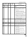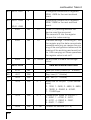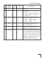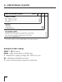
1
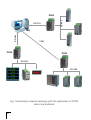
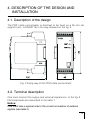
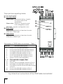
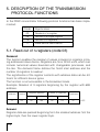
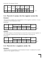
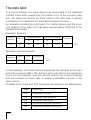
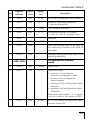
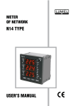
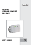
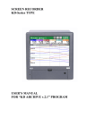
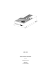
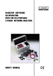
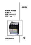
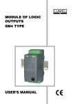
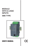
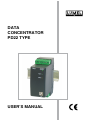
DATA CONCENTRATOR PD22 TYPE USER’S MANUAL Contents: 1. APPLICATION ..................................................................... 5 2. SET OF THE DELIVERED DATA CONCENTRATOR ........................... 7 3. BASIC REQUIREMENTS AND SAFETY SERVICE ............................. 7 4. DESCRIPTION OF THE DESIGN AND INSTALLATION ....................... 8 4.1.Description of the design .................................................................. 8 4.2.Terminal description ......................................................................... 9 4.3.Instalacja portu COM dla Windows ................................................. 10 4.4.Instalacja sterowników portu COM na komputerze . ........................ 11 4.5.Concentrator configuration............................................................... 11 5. DESCRIPTION OF THE TRANSMISSION PROTOCOL FUNCTIONS....... 5.1.Readout of n-registers (code 03) .................................................... 5.2.Record of values to the register (code 06) ...................................... 5.3.Record to n-registers (code 16) ...................................................... 5.4.Identifying report of the device (code 17) ....................................... 13 13 14 14 15 6. ERROR CODES ................................................................. 16 7. REGISTER MAP OF THE PD22 DATA CONCENTRATOR................... 18 8. TECHNICAL DATA .............................................................. 29 9. ORDERING CODES ............................................................. 31 10. MAINTENANCE AND GUARANTEE ........................................... 32 1. APPLICATION The PD22 data concentrator is destined for telemetering computer systems as an intermediate element in the data exchange between the object side and the master system. The data concentrator speeds up the data exchange between devices and the master system. Moreover it allows to increase the number of devices connected to the system. Two serial ports are used for communication. The first port (Port 1) having two RS-485 interface systems, destined to communicate with devices working in the object. The second port (Port 2) has RS-485, RS-232 C and USB interfaces, destined to communicate with the master system through wire links. An asynchronous MODBUS character communication protocol has been implemented on the serial link. The concentrator has a real time clock. Parameter set of the concentrator serial link: - address1... 247 - baud rate 1200, 2400, 4800, 9600, 19200, 38400, 57600, 115200 bit/s, - working mode ASCII, RTU, - information unit ASCII: 8N1, 7E1, 7O1, 7N2 RTU: 8N2, 8E1, 8O1, 8N1 The data concentrator realises following functions: - readout of process parameters values from devices which are accessible as concentrator parameters, - archiving of process data with a defined frequency, which are made available on demand for the master system (390000 records), - archiving of emergency events (44400 events), - data exchange consisting in transmission of demands from the master system to the specific device, eg. readout or parameter record. The exemplary network topology with the use of data concentrators is shown on the Fig.1. RS-485 RS-232 RS-485 PD22 USB PD22 PD22 RS-485 RS-485 Fig 1 Exemplary network topology with the application of PD22 data concentrators 2. PD22 DATA CONCENTRATOR SET The PD22 data concentrator set includes: - PD22 data concentrator...................................... 1 pc - PD22 user’s manual........................................... 1 pc - guarantee card................................................... 1 pc - CD diskette with the PD22Wiz configuration program and controllers of the USB port........... 1 pc When unpacking the data concentrator, please check whether the type and version code on the data plate correspond to the order code. 3. BASIC REQUIREMENTS, SAFETY SERVICE Symbols located in this user’s manual mean: WARNING! Warning of potential, hazardous situations. Especially important. One must acquaint with this before connecting the concentrator. The non-observance of notices marked by these symbols can occasion the damage of the instrument. CAUTION! Designates a general useful note. If you observe it, handling of the concentrator is made easier. One must take note of this, when the instrument is working inconsistently to the expectations. Possible consequences if disregarded! The removal of the concentrator housing during the guarantee contract period may cause its cancellation. In the security scope the concentrator meets the requirements of the EN 61010 -1 standard. Remarks concerning the operator safety service: - The PD22 converter is destined to be mounted on a 35 mm rail. - Non-authorized removal of the required housing, inappropriate use, incorrect installation or operation creates the risk of injury to personnel or damage to equipment. For more detailed information please study the User’s Manual. - All operations concerning transport, installation, and commissioning as well as maintenance must be carried out by qualified, skilled personnel and national regulations for the prevention of accidents must be observed. - According to this basic safety information, qualified, skilled personnel are persons who are familiar with the installation, assembly, commissioning, and operation of the product and who have qualifications necessary for their occupation. - Before switching the concentrator on, one must check the correctness of connection to the network. - Do not connect the concentrator to the network through an autotransformer. 4. DESCRIPTION OF THE DESIGN AND INSTALLATION 4.1. Description of the design The PD21 data concentrator is destined to be fixed on a 35 mm rail support (acc. to EN 60715) in the way showed on the fig. 2. Fig. 2 Fixing way of the PD22 data concentrator 4.2. Terminal description One must connect the supply and external signals acc. to the fig. 3. Particular leads are described in the table 1. Notice: One must take a special note to the correct connection of external signals (see table1). There are three signalling diodes on the frontal plate: D1 two-colour diode Green colour - continuous lighting - signals the correct work of the concentrator. Green colour - flickering - signals the work in the configuration mode. Red colour - signals a configuration error. D1 D2 D3 D2 Green diode signals the transmission of data from the side of devices of Slave type D3 Yellow diode signals the transmission of data from the side of devices of Master type Description of PD22 data concentrator Table 1 Terminal Terminal description 1 2 3 4 5 6 7 8 9, 10 11 12 13 14 15 16 Output +5 V (for bus polarisation) Line A of the first RS-485 interface of Port 1 Line B of the first RS-485 interface of Port 1 Line GND of RS-485 interface of Port 1 Line GND of RS-485 interface of Port 1 Line B second RS-485 interface of Port 1 Line A second RS-485 interface of Port 1 Output +5 V (for bus polarisation) Concentrator supply lines Not used Output TxD of the RS-232 interface of Port 2 Input RxD of the RS-232 interface of Port 2 Line GND of the RS-232 and RS-485 interface of Port 2 Line A of the RS-485 interface of Port 2 Line B of the RS-485 interface of Port 2 Fig.3 Electrical connections of the PD22 data concentrator. 10 The PD22 data concentrator has two serial ports, the port 1 and the port 2. The Port 1 is destined to communicate with devices of Slave type. Two RS-485 interfaces systems are connected to the Port 1. The operation of the two systems is identical. Interface systems are electrically connected and galvanically isolated from the remaining system. Interface lines are connected to terminals 1,2,3,4 for the first system, and 5,6,7,8 for the second system. The port 2 is connected to the RS-232C and RS-485 interface system. The RS-485 interface systems are electrically connected to the port. The RS-485 bus enables the direct addition up to 32 systems of the RS-485 interface. The maximal length of the bus depends on the baud rate and includes itself in limits from several tens of meters for high speeds, and up to ca 1200 meters for small speeds, e.g. 9600 bps. The Port 2 is destined to communicate the concentrator with an external device of Master type. The port 2 is connected to RS-485, RS-232 and USB interface systems. Interface systems are connected electrically to the port. The RS-485 interface system enables to connect the concentrator to the RS-485 serial bus. Its lines are led out to terminals 14, 15, 16. RS-232C and USB interfaces are destined to the connection with devices having such interfaces, such as e.g.: computer. Signals of the RS-232 interface are led out on terminals 12, 13, 14. The USB interface is accessible on the concentrator frontal plate. RS-485, RS-232 and USB interfaces cannot be used simultaneously. The PD22Wiz program is added to the concentrator on a CD diskette and it is destined for configuration and PD22 service. 4.3. Installation of the COM port for Windows The USB port for the PD22 concentrator uses controllers FTDIBUS Driver and FTDIPORT Driver licensed by the Future Technology Devices International Ltd. Company. This software creates in the system, the new USB Serial Converter device and assigned to it Port(Com) - USB Serial Port. 11 The installation of the controller in the Windows system causes the addition of a successive COM serial port to the list of ports serviced by the operating system. 4.4. Installation of COM port controllers on the computer On the CD diskette added to the concentrator there are catalogues with controllers for following operating systems: - WIN_XP: Windows 2000, Windows XP, Windows Vista, Windows Server 2003. - WIN_XP_64: Windows Vista x64, Windows XP x64, Windows Server 2003 x64. NOTICE: Controllers do not co-operate with 98 and ME Windows systems Installation in systems: Windows 2000, Windows XP, Windows Vista and Windows Server 2003. In order to install controllers for these systems, one must start the program workable from the catalogue with the controller for the given system: - WIN_XP\CDM_Setup.exe (for Windows 2000, Windows XP, Windows Vista and Windows Server 2003) - WIN_XP_64\ CDM_x64_Setup.exe (for Windows XP x64, Windows Vista x64 and Windows Server 2003 x64). This software will install in the system controllers for new devices and ports. Next, one must connect the concentrator which will be found and identified by the system as USB Serial Converter and will be assigned a port (COM) for it - USB Serial Port. 12 4.5. Koncentrator configuration Before starting concentrator applications, one must set transmission parameters for the port, that means define the network address, baud rate and the transmission mode for the port 2. Manufacturer settings for these parameters arte as follows: Address254 Mode RTU 8N1 Baud rate115200 bit/s In order to perform changes of these settings, one must: - connect the concentrator by the USB interface with the PC computer, - turn the concentrator supply on, - press the push-button of the concentrator configuration (fig.4), untill the green diode begins to flicker signaling the configuration mode. Start the PD22Wiz program and by its help configure parameters into required. Exit from the concentrator configuration mode by p[ressing the configuration push-button till the moment as the green diode transits to a continuous lighting, signaling the normal working mode. Fig. 4 Location of the push-button to configure the PD22 data concentrator 13 5. DESCRIPTION OF THE TRANSMISSION PROTOCOL FUNCTIONS In the PD22 concentrator following protocol functions has been implemented: Code Signitication 03 Readout of n-register 06 Record of a single register 16 Record of n-registers 17 Slave device identification 5.1. Read-out of n-registers (code 03) Demand: The function enables the readout of values included in registers in being addressed slave device. Registers are 16 or 32-bit units, which can include numerical values bounded with changeable processes, and the like. The demand frame defines the 16-bit start address and the number of registers to readout. The signification of the register contents with address data can be different for different device types. The function is not accessible in the broadcast mode. Example: Readout of 3 registers beginning by the register with 6Bh address. Address Function 11 03 Register address Number of registers Hi Lo Hi Lo 00 6B 00 03 Checksum 7E LRC Answer: Register data are packed beginning from the smallest address: first the higher byte, then the lower register byte. 14 Address Example: the answer frame Function 11 Value in Value in Value in Number the regist. the regist. the regist. Checksum of 107 108 109 bytes Hi Lo Hi Lo Hi Lo 03 06 02 2B 00 00 00 64 55 LRC 5.2. Record of values into the register (code 06) Demand: The function enables the modification of the register contents. It is accessible in the broadcast mode. Example: Address Function 11 06 Register address Value Hi Lo Hi Lo 00 87 03 9E Checksum C1 LRC Answer: The right answer to the demand to record the value into the register is the message retransmission after the operation carrying out. Example: Address Function 11 06 Register address Value Hi Lo Hi Lo 00 87 03 9E Checksum C1 LRC 5.3. Record into n-registers (code 16) Demand: The function is accessible in the broadcast mode. It enables the modification of the register contents. 15 Example: Record of two registers beginning from the register with the address 136. Register Number of Number Address Function address registers of bytes Hi Lo Hi Lo 11 10 00 87 00 02 04 Data Checksum Data Hi Lo Hi Lo 00 0A 01 02 45 LRC Answer: The correct answer includes the unit slave address, function code, starting address and the number of recorded registers. Example: Address Function 11 10 Register address Number of registers Hi Lo Hi Lo 00 87 00 02 Checksum 56 LRC 5.4. Report identifying the device (code 17) Demand: This function enables the user to obtain information about the device type, status and configuration depending on this. Example Address Function Checksum 11 11 DE LRC Answer: The field „Device identifier” in the answer frame means the unique identifier of this class of devices, however the other fields include parameters depended on this function. Example concerning the PD21 concentrator Slave address Function Number of bytes Device identifier Device state 11 11 2 0xAB FF 16 Checksum 6. ERROR CODES When the master device is transmitting a demand to the slave device then, except for messages in the broadcast mode, it expects a correct answer. After transmitting the demand of the master unit, one of the four possibilities can occur: l If the slave unit receives the demand without a transmission error and can execute it correctly, then it returns a correct answer, l If the slave unit does not receive the demand, no answer is returned. Timeout conditions for the demand will be fulfilled in the master device program. l If the slave unit receives the demand, but with transmission errors (even parity error, checking sum LRC or CRC error), no answer is returned. Timeout condition for the demand will be fulfilled in the master device program. l If the slave unit receives the demand without a transmission error but cannot execute it correctly (e.g. if the demand is the readout of a non-existent bit output or register), then it returns the answer including the error code, informing the master device about the error reason. A message with an incorrect answer includes two fields distinguishing it from the correct answer. The function code field: In the correct answer, the slave unit retransmits the function code from the demand message in the field of the answer function code. All function codes have the most significant bit (MSB) equal zero (code values are under 80h). In the incorrect answer, the slave unit sets up the MSB bit of the function code at 1. This causes that the function code value in the incorrect answer is exactly of 80h greater than it would be in a correct answer. On the base of the function code with a set up MSB bit, the program of the master device can recognize an incorrect answer and can check the error code on the data field. 17 The data field: In a correct answer, the slave device can return data to the data field (certain information required by the master unit). In the incorrect answer, the slave unit returns the error code to the data field. It defines conditions of the slave device that had produced the error. An example considering a demand of a master device and the incorrect answer of the slave unit has been shown below. Data are in the hexadecimal shape. Example: demand Slave address Function 0A 01 Variable address Number of variables Hi Lo Hi Lo 04 A1 00 01 Checksum 4F LRC Example: incorrect answer Slave address Function Error Checksum 0A 81 01 73 LRC In this example, the master device addresses the demand to the slave unit with number 0 (0Ah). The function with code (01) is not implemented in the concentrator, then the device returns the incorrect answer with the number 01 error code. It means a forbidden function in the slave device. Possible error codes and their meanings are shown in the table below. 18 Code Meaning 01 Forbidden function 02 Forbidden data address 03 Forbidden data value 04 Demand during the realization 05 Impossible demand realization 7. REGISTER MAP OF THE PD22 DATA CONCENTRATOR In the PD22 data concentrator data are placed in 16-bit or 32-bit registers. Process variables and concentrator parameters are situated in the area of registers in the way depended on the variable value type. Bits in the 16-bit and 32-bit registers are numbered from the lowest to the highest bit ( b0-b15) or (b0-b32). 32-bit registers with addresses 1-999 include float numbers according to the IEEE-754 standard. 32-bit registers with addresses 8000-8169 include long type numbers. The map of registers is divided in following areas: Table 1 Address range Value type Description 1 - 999 float (32 bits) The value is placed in the 32-bit register. The register includes data read out from devices connected to the port 1 of the concentrator. The signification of particular registers depends on the configuration. Registers can be read out and recorded. 1000 - 2999 float (32 bits) The value is placed in two successive 16-bit registers. Registers contain the same data as 32-bit registers from the area 1...999, e.g. registers 1000 and 1001 contain the value from the register 1, registers 1002 and 1003 contain the value from the register 2, etc. Registers can be read out and recorded. 4000 - 4569 8000 integer (16 bits) The value is placed in one 16-bit register. The description of registers is included in the Table 1. Registers can be read out and recorded. long (32 bits) The register contains the device status. Successive register bits of value 1 mean: b0 - error of the RAM memory, b1 - transmission error from the device side, b2 - filled data archiving buffer, b3 - filled event archiving buffer. The register is for readout only. 19 8001, 8002 long (32 bity) The value is placed in the 32-bit register. Successive register bits contain the index of current event occurrence. The bit 0 value means that the event does not occur. Registers are for readout only. 8003 - 8034 long (32 bity) The value is placed in the 32-bit register. Successive register bits contain the index of data credibility from registers 1...999. The bit 0 value means that the data is not credible (e.g. because of the lack of transmission from the device). Registers are for readout only. 8100 - 8169 long (32 bity) The value is placed in two successive 16-bit registers. Registers contain the same data as 32-bit registers from the area 8000-8034. E.g. registers 8100 and 8101 contain value from the register 8000, registers 8102 and 8103 contain value from the register 8001, etc. Registers are for readout only. The PD22 concentrator is an active device (master) in relation to the devices connected from the object side, however it is a passive (slave) device in relation to the devices connected from the computer side. According the entered configuration, the concentrator reads out parameters from devices connected from the Port 1 side, with a defined frequency. The archiving of data read out from the devices follows with the frequency defined in the configuration. Data are stored in the concentrator memory which is battery supported. Moreover, alarm events defined in the configuration are recognised and archived at the moment of their occurrence. In the archive buffer, one can store maximum 390000 data records and 44400 events. After the buffer filling. current data are stored and the oldest are lost. 20 The PD22 concentrator additionally enables the transmission of demands to particular devices. Each demand to the slave devices depends on the device type and is defined in the User’s Manuals of interfaces of particular devices. Concentrator tasks are defined through registers described in the table 2. Contents of 16-bit registers with addresses from 4000 to 6999. Operations mean admissible actions on registers R - readout, W - Record Table 2. Item Register address opera -tions Range unit Description Configuration of readout operations or parameter recording from/ to scanned devices 4000...4009 1 4000 RW 0...32000 Safety code 2 4001 RW 0...3 Operation code: 0 - readout of the configuration table element, 1 - record of the configuration table element, 2 - erasing of the configuration table element, 3 - erasing of all table elements. Operations with codes 1, 2, 3 require a correct code in the register 4000. 3 4002 RW 0...99 No of the configuration table element 4 4003 RW 0, 1 5 4004 RW 1...999 PD22 register address 6 4005 RW 1...255 Address of the scanned device Status: 0 - operation disabled, 1 - operation enabled 21 continuation Table 2. 7 4006 RW 8 4007 RW 1...20 Address of the basic device register Number of registers 9 4008 RW Lower byte 0...7 Register type: 0 - char (8-bit int), 1 - 16-bit int, 2 - 32-bit long, 3 - 32-bit float, 4 - 32-bit float in the shape of 2*16 bit (sequence of bytes 12 34), 5 - 32-bit float in the shape of 2*16 bit (sequence of bytes 21 43), 6 - 32-bit float in the shape of 2*16 bit (sequence of bytes 43 21), 7 - 32-bit float in the shape of 2*16 bit (sequence of bytes 34 12) Particular bits define the readout way and the record of device registers: higher byte 7654 3210 bit 0..3 -0 readout function fc=03 1 readout function fc=04 bit 4..7 -0 record function fc=16 1 record function fc=06 10 4009 RW 1...64000s Scanning frequency Configuration of archived parameters 4010...4019 11 4010 12 4011 22 RW 0...32000 0...3 Safety code Operation code: 0 - read-out of the element from the configuration table, 1 - record of the configuration table element, 2 - erasing of the configuration table element, 3 - erasing of all configuration table elements. Operations with codes 1, 2, 3 require a correct code in the register 4010. continuation Table 2. Item Register address Opera -tions Range unit Description 13 4012 RW 0...99 No of the configuration table element 14 4013 RW 0, 1 15 4014 RW 1...999 16 4015 RW 0...3 17 4016 18 4017 RW 19 4018 RW High (dn) highest part of dn data to the archiving condition (dn data of float type) 20 4019 RW Low (dn) lowest part of dn data to the archiving condition. Status: 0 - archiving disabled, 1 - archiving enabled PD22 register address Archiving condition: 0 - always, 1 - >dn, 2 - <dn, 3 - change >|dn| reserved 0...64000s Archiving frequency Configuration of archived events 4020...4029 21 4020 RW 0...32000 22 4021 RW 0...3 Safety code Operation code: 0 - read-out of the element from the configuration table, 1 - record of the configuration table element, 2 - erasing of the configuration table element, 3 - erasing of all configuration table elements. Operations with codes 1, 2, 3 require a correct code in the register 4020. 23 4022 RW 0...99 No of the event configuration table element (event ID) 23 continuation Table 2. 24 4023 RW 0, 1 Status: 0 - archiving disabled, 1 - archiving enabled 25 4024 RW 1...999 PD21 register address 26 4025 RW 1...3 Event archiving condition: 1 - >dn, 2 - <dn, 3 - change > |dn| 27 4026 28 4027 Reserved 29 4028 RW High (dn) highest part of dn data for the event archiving condition (dn data of float type) 30 4029 RW Low (dn) lowest part of the dn data for the archiving condition. Reserved Configuration of a single demand into the device 4100...4122 31 4100 RW 0...3 Operation code: 0 - do nothing, 1 - send the frame to the device, 2 - read out the answer when the status = 1, 3 - erase the demand. 32 4101 RW 0...4 Status: 0 - lack of demand, 1 - ready answer, 2 - demand received for realisation, 3 - demand under realisation, 4 - demand realisation impossible 33 4102 RW 2...40 34 4103 RW Frame beginning: address + FC 35 4104 RW Register address Hi + Lo 36 ... RW Successive frame bytes 37 4122 RW Last two frame bytes 24 Number of frame bytes continuation Table 2. Item Register address Opera -tions Range unit Description Data read-out from the archive buffer 4200...4255 Operation code. Record of below values into the register occasions the realisation of following functions: 0 - do nothing 1 - set the time on the value from registers 4201, 4202 or later 2 - set the time on the buffer beginning 3 - time readout of the current readout from the archive buffer 4 -readout from the archive buffer of n registers (n in the register No 4203) 5 - the readout of the register 4205 occasions the readout of n registers from the archive buffer (n in the register No 4203). 38 4200 RW 39 4201 RW 40 4202 RW 41 4003 RW 5...90 Number of registers which is to be read out from the buffer (multiplicity of 5) 42 4004 RW 0...4 Readout status: 0 - out of date data, lack of order (instruction), 1 - order realised with success, 2 - impossible realisation of task, buffer empty, 3 - less of data have been read out than required 4 - lack of data in the buffer from the defined time in registers 4201, 4202 and later. 0...5 High (tm) highest part of the time in seconds since 1.01.1970 on which one must set the data readout from the archive buffer (tm - data of long type). Low (tm) lowest time part as above. 25 continuation Table 2. 43 4205 R 0,5...90 Number of registers read out from the buffer 44 4206 R 0...999 No of the archived register 45 4207, 4208 R Archiving time in the format given at the description of registers 4201, 4202 46 4209 R High (x) highest part of the archived register value (x - data of float type) 47 4210 R Low (x) lowest part of the archived register value. 48 4211...4215 R Analogous contents as in registers 4206...4210 for the next archived parameter. 49 4216...4220 R Analogous contents as in registers 4206...4210 for the next archived parameter. 50 4221...4225 R Analogous contents as in registers 4206...4210 for the next archived parameter. 51 4226...4230 ... 4251...4255 R Analogous contents as in registers 4206...4210 for the next archived parameter. 4300...4345 52 26 4300 Read-out of events from archiving buffer RW 0...5 Operation code. 0 - do nothing 1 - set the time on the value from registers 4301, 4302 or later 2 - set the time on the buffer beginning 3 - time readout of the current readout from the event buffer 4 - readout from the event buffer f n registers (n in the register No 4303) 5 - the read-out of the register 4305 occasions the readout from the event buffer of n registers (n in the register No 4303) continuation Table 2. Item Register address Opera -tions Range unit 53 4301 RW 54 4302 RW 55 4303 RW 4...80 Number of registers which is to be read-out from the buffer (multiplicity of 4) 56 4304 RW 0...4 Readout status: 0 - out of date data, 1 - order realised with success, 2 - realisation of task impossible, buffer empty 3 - less of events has been read out than required, 4 - lack of events in the buffer from the defined time in registers 4201, 4202 and later. 57 4305 R 0,4,...80 58 4306 R 0...99 59 4307, 4308 R 60 4309 R 61 4310...4313 R Analogous contents as in registers 4306...4309 for the next archived event. 62 4314...4317 R Analogous contents as in registers 4306...4309 for the next archived event. Description High (tm) highest time part in seconds since 1.01.1970 on which one must set the data readout from the event buffer (tm - data of long type) Low (tm) lowest time part as above. Number of registers read out from the buffer Event identifier ID Archiving time in the format given when describing registers 4301, 4302. 0,1 Event status: 1 - occurrence, 0 - withdrawal 27 continuation Table 2. 63 4318...4321 R Analogous contents as in registers 4306...4309 for the next archived event. 64 4322...4325 ... 4342...4345 R Analogous contents as in registers 4306...4309 for the next archived event. 65 4400 RW 0,1 Index (=1) defining whether the device reset has occurred. The record of 0 into the register causes the index erasing. 66 4500 RW 0,1 Standard settings. The writing of 1 into the register and the data concentrator renewed switching on causes the erasing of the configuration tables and the erasing of the archiving and event buffer. After carrying out these operations the register value is set on 0. 67 4505 RW 0...32000 4510...4512 Safety code to create the configuration. Date and internal clock time 68 4510 RW Year (rrrr-2000), month (2 * 8 bitów) 69 4511 RW Day, hour (2 * 8 bitów) 70 4512 RW Min., sec. (2 * 8 bitów) 71 4513 RW 0...7 Baud rate for the port 1 (from device side): 0 - 1200, 1 - 2400, 2 - 4800, 3 - 9600, 4 - 19200, 5 - 38400, 6 - 57600, 7 - 115200 bps. 72 4514 RW 0...7 Transmission mode for the port 1: 0 - A8N1, 1 - A7N2, 2 - A7E1, 3 - A7O1, 4 - R8N2, 5 - R8E1, 6 - R8O1, 7 - R8N1 73 4515 RW 1...50 Timeout for devices (*0.1 s) 28 continuation Table 2. Item Register address Opera -tions Range unit Description 74 4516 RW 1...254 75 4517 RW 0...7 Address Baud rate for the Port 2 (from the master device): 0 - 1200, 1 - 2400, 2 - 4800, 3 - 9600, 4 - 19200, 5 - 38400, 6 - 57600, 7 - 115200 bps. 76 4518 RW 0...7 Transmission mode for the Port 2: 0 - A8N1, 1 - A7N2, 2 - A7E1, 3 - A7O1, 4 - R8N2, 5 - R8E1, 6 - R8O1, 7 - R8N1 77 4519 RW 0 78 4520 RW 0,1 4550...4569 RW Connection type for the Port 2: 0 - direct connection Apply: force the apply of settings from registers 4516...4519 Initiating a sequence of orders sent to the modem after switching the data concentrator and the modem on. Each register includes two ASCII characters. The sequence must be ended by the CR character (0DH). Standard sequence of orders: „ATQ0V0&C1&D1M1L1S0=10\r” 29 8. TECHNICAL DATA Serial port 1: - baud rate1200, 2400, 4800, 9600, 19200, 38400, 57600, 115200 bit/s, - information unit1 start bit, 7 or 8 data bits, 1 bit for even/odd parity; 1 or 2 stop bits, - interface2 x RS-485 Serial port 2: - baud rate1200, 2400, 4800, 9600, 19200, 38400, 57600, 115200 bit/s, - information unit1 start bit, 7 or 8 data bits, 1 bit for even, odd parity; 1 or 2 stop bits, - interfejs RS-485, RS-232, USB 1.1 - cable no longer than 3 m Transmission protocol MODBUS Power consumption 4 VA Rated operation conditions: - supply voltage20...24...50 V a.c./d.c. or 85...230...253 V a.c./d.c. - supply voltage frequency40...50/60...440 Hz - ambient temperature 0...23...55°C - relative air humidity < 95% (condensation inadmissible) - external magnetic field < 400 A/m - working position any 30 Storage and transport conditions: - ambient temperature - relative air humidity - 20...70°C < 95% (condensation inadmissible) Ensured protection class by the frontal plate: - from the frontal plate - from the terminal side IP 40 IP 20 Dimensions45 ´ 120 ´ 100 mm Weight < 0,25 kg Housing adapted to be mounted on a 35 mm rail Elektromagnetic compatibility: - immunity acc. to EN 61000-6-2 - emission acc. to EN 61000-6-4 Safety requirements acc. to EN 61010-1: - installation category III - pollution level 2 Maximal phase-to-earth: working voltage: - for the supply circuit300 V - for other circuits50 V 31 9. ORDERING CODES Data concentrator danych PD22 - X XX X Supply voltage 85... 253 V a.c./d.c. ................................................... 1 20... 50 V a.c./d.c. ..................................................... 2 on order ..................................................................... X Version catalogue............................................................................ 00 custom-made*................................................................... XX Acceptance tests without an extra quality inspection certificate ............................ 8 with an extra quality inspection certificate ................................. 7 acc. user’s agreement* .............................................................. X * The code number will be established by the manufacturer. Example of order coding: PD22 1 00 7 means: PD22 - data concentrator of PD22 type, 1 - adapted for supply voltage: 85...253 V a.c./d.c., 00 - catalogue (standard) version, 7 - with an extra quality inspection certificate. 32 10. MAINTENANCE AND GUARANTEE The PD21 concentrator does not require any periodical maintenance. The applied battery requires exchange every 5 years. In case of some incorrect operations: 1. In the period of 12 months from the date of purchase: One should take the instrument down from the installation and return it to the Manufacturer Quality Control Dept. If the unit has been used in compliance with the instructions, the Manufacturer guarantees to repair it free of charge. 2. After the guarantee period: One should turn over the instrument to repair in a certified service workshop. The disassembling of the housing causes the cancellation of the granted warranty. Spare parts are available for the period of five years from the date of purchase. Our policy is one of continuous improvement and we reserve the right to make changes in design and specifications of any products as engineering advances or necessity requires and revise the above specifications without notice. 33 34 35 SALES PROGRAM MEASUREMENT DIGITAL and BARGRAPH PANEL METERS CONTROL MEASURING TRANSDUCERS RECORDING ANALOG PANEL METERS (DIN INSTRUMENTS) ANALOG and DIGITAL CLAMP-ON METERS INDUSTRIAL and HOUSEHOLD CONTROLLERS CHART AND PAPERLESS RECORDERS POWER CONTROL UNITS and INVERTERS LARGE SIZE NUMERIC and ALPHANUMERIC DISPLAYS AUTOMOTIVE DASHBOARD INDICATORS ACCESSORIES FOR MEASURING INSTRUMENTS MEASURING SYSTEMS (ENERGY, HEAT, CONTROL) CUSTOM-MADE PRODUCTS WE ALSO OFFER OUR SERVICES IN THE PRODUCTION OF: ALUMINIUM ALLOY PRESSURE CASTINGS PRECISION ENGINEERING AND THERMOPLASTICS PARTS PRESSURE CASTING DIES AND OTHER TOOLS QUALITY PROCEDURES: According to ISO 9001 and ISO 14001 international requirements. All our instruments have CE mark . For more information, please write to or phone our Export Department Lubuskie Zak³ady Aparatów Elektrycznych - LUMEL S.A. ul. Sulechowska 1, 65-022 Zielona Góra, Poland Export Department: Tel.: (48-68) 329 53 02 or 53 04 Fax: (48-68) 325 40 91 e-mail: [email protected] 36 PD22-07 Tel.: (48-68) 329 51 00 (exchange) Fax: (48-68) 329 51 01 www.lumel.com.pl e-mail:[email protected]