1
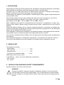
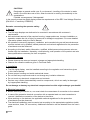
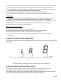
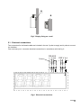
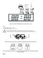
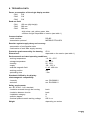
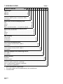
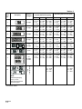
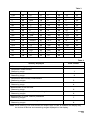
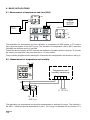
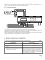
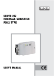
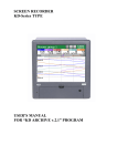
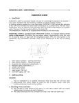
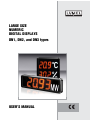
LARGE SIZE NUMERIC DIGITAL DISPLAYS DN1, DN2, and DN3 types USERS MANUAL LARGE SIZE NUMERIC DIGITAL DISPLAYS DN1, DN2 and DN3 types USERS MANUAL CONTENTS: 1. APPLICATION ........................................................................................................................ 5 2. DISPLAY SET ......................................................................................................................... 5 3. BASIC REQUIREMENTS, SAFETY INFORMATION ........................................................... 5 4. CHOICE OF DISPLAY DIGIT DIMENSIONS ........................................................................ 7 5. DESIGN DESCRIPTION AND INSTALLATION .................................................................... 7 5.1 Electrical connections ..................................................................................................... 9 6. TECHNICAL DATA ............................................................................................................... 11 7. ORDERING CODES ............................................................................................................. 12 8. BASIC APPLICATIONS ....................................................................................................... 16 9. BEFORE A DAMAGE WILL BE SUBMITTED .................................................................... 17 10. MAINTENANCE AND GUARANTEE ................................................................................... 18 ! " 1. APPLICATION Digital displays of DN type can be applied for the visualisation of essential parameters in automation and measurement processes when supervising the quality or working safety. Information put in a visible place helps in the efficient work execution in industrial communication, logistics, automation and control technology, and material handling. These displays are destined to be installed in: industrial plants, sports objects, trade buildings and communication areas. The character height ensures a good visibility and read-out from a long distance, up to 120 m. These digital displays are offered in four colours: red, green, yellow and blue. Digit heights can be: DN1 - 100 mm, DN2 - 200 mm, DN3 - 300 mm. Basic installations are applied for measurements and indications of: temperature, humidity, time, pressure, flow, rotations, pulses, energy, and also the gas content , material amount or any physical quantity. These DN displays together with an external measuring element or transducer can display any physical quantity and co-operate with external measuring devices equipped with an RS-485 digital output with the MODBUS RTU/ASCII protocol. The configuration of transmission parameters and measuring ranges is made agree with the customer. The standard version includes the digital diode display field and the unit field. The number of characters and the display colour are expressed by the ordering code and defined by the customer. The display field brightness is established automatically in accordance with external conditions. The unit can be selected from the list inserted in the ordering code or defined by the user. 2. DISPLAY SET The display set includes: - digital display ............................................ 1 pc - users manual ........................................... 1 pc - guarantee card ......................................... 1 pc - connectors for the female cable .............. 2 pcs Measuring devices (as per order) In the DN3-8x... version, the set is additionally composed of: - DCF receptor - CT1 sensor 3. INSTALLATION AND BASIC SAFETY REQUIREMENTS Symbols located in this service manual mean: ! WARNING! Warning of potential, hazardous situations. Especially important. One must acquaint with this before connecting the digital display. The non-observance of notices marked by these symbols can occasion severe injuries of the personnel and the damage of the device. # CAUTION! Designates a general useful note. If you observe it, handling of the device is made easier. One must take note of this, when the device is working inconsistently to the expectations. Possible consequences if disregarded! In the security scope the digital display meets the requirements of the EEC Low-Voltage Directive (EN 61010 -1 issued by CENELEC). ? Remarks concerning the operator safety: 1. General l l l l ! The DN large displays are destined to be mounted in accordance with customers requirements. Non-authorized removal of the required housing, inappropriate use, incorrect installation or operation creates the risk of injury to personnel or damage to equipment. For more detailed information please study the Users Manual. All operations concerning transport, installation, and commissioning as well as maintenance must be carried out by qualified, skilled personnel and national regulations for the prevention of accidents must be observed. According to this basic safety information, qualified, skilled personnel are persons who are familiar with the installation, assembly, commissioning, and operation of the product and who have qualifications necessary for their occupation. 2. Transport, storage l l Please observe the notes on transport, storage and appropriate handling. Observe the climatic conditions given in Technical Data. 3. Installation l l l l l The DN digital display must be installed according to the regulation and instructions given in this Users Manual. Ensure proper handling and avoid mechanical stress. Do not bend any components and do not change any insulation distances. Do not touch any electronic components and contacts. Devices may contain electrostatically sensitive components, which can easily be damaged by inappropriate handling. Do not damage or destroy any electrical components since this might endanger your health! 4. Electrical connection l l l l $ Before switching the device on, one must check the correctness of connection to the network. In case of the protection terminal connection with a separate lead one must remember to connect it before the connection of the device to the mains. When working on live devices, the applicable national regulations for the prevention of accidents must be observed. The electrical installation must be carried out according to the appropriate regulations (cable cross-sections, fuses, PE connection). Additional information can be obtained from the users guide. l l l l The documentation contains information about installation in compliance with EMC (shielding, grounding, filters and cables). These notes must be observed for all CE-marked products. The manufacturer of the digital display or installed devices is responsible for the compliance with the required limit values demanded by the EMC legislation. Do not connect the digital display to the mains through an autotransformer. The RS-485 socket serves only to connect devices working with the MODBUS protocol. 5. Operation l l l Measuring systems including DN digital displays, must be equipped with protection devices according to the corresponding standard and regulations for prevention of accidents. After the display has been disconnected from the supply voltage, live components and power connections must not be touched immediately because capacitors can be charged. The housing must be closed during operation. 6. Maintenance and servicing l l l l Please observe the manufacturers documentation. Read all product-specific safety and application notes in this Users Manual. Before taking the device housing out, one must turn the supply off. The removal of the device housing during the guarantee contract period may cause its cancellation. 4. CHOICE OF DISPLAY DIGIT DIMENSIONS To ensure the optimal read-out for each application one must choose the appropriate height of the display digit. DN3 DN2 h=300mm 130 120 110 100 90 80 70 60 50 40 30 20 10 0 h=100mm h=200mm DN1 Distance [m] Fig.1 Dependence between the read-out distance and the digit size 5. DESIGN DESCRIPTION AND INSTALLATION The display housing is made of steel sheet. The protection level of the housing is IP54. Housing dimensions depending on the version are presented in the table 4. The display has two ways of fixing. Assembly holes situated on the rear wall enable the suspension on a wall. Additional grips (detail B) serve to the display suspension. % c a b B A 5.4 d 18 A O10.5 L 19 B 8 16 O5.5 Fig 2 Display dimensions and layout of holes and fixing grips Fig. 3 Display suspension & Fig.4 Rigid suspension B B Fig.5 Display fixing on a wall 5.1. Electrical connections Two connectors for the female cable are included in the set: 3-polar to supply and 4-polar to connect the interface. One must carry out connector electrical connections in accordance with the fig. 6 RS-485 Screen A B GND 230 V a.c. L 1 2 3 N PE 1 2 Fig.6. Electrical connections ' 230 V a.c. Pt100 U GND DCF RS-232 N L 2 3 1 1 PE 1 2 2 3 Fig.7 Connection of DN3-8xxxxxxx ( temperature + time) Wires: - maximal wire section: 1.5 mm2 - maximal cable diameter: up to 7 mm GND B A 3 2 1 2 1 G2 G1 L N PE 230 V a.c. For the interface connection, a double spiral in a screen is recommended The screen must be connected with the PE terminal of the G2 interface socket RS-485 ? Fig. 8 Description of sockets to connect the supplying network and the interface Pt100/1,3850 RS-232 1 L PE 2 GND 2 G2 1 N 3 +U 2 G3 1 DCF 3 230 V a.c. Fig. 9 Description of sockets to connect the mains and application elements: temperature and time for DN3 6. TECHNICAL DATA Power consumption of the single display module: - DN1 2W - DN2 5W - DN3 5W Read-out field: - DN1 100 mm (digit height) - DN2 200 mm - DN3 300 mm - digit colour: red, yellow, green, blue - number of digits: depended on version (see table 1) Communication: - serial interface - transmission protocol RS-485 MODBUS RTU/ASCII Reaction against supply decay and recovery: - preservation of configuration data - continuation of work after supply recovery Protection grade ensured by the housing IP 54 Dimensions: depended on the version (see table 1) Environmental and rated operating conditions: - working temperature -10...23...55°C - storage temperature 20... 80°C - humidity 25... 95% - supply 195... 253 V - external magnetic field 0...40...400 A/m. - working position any - preheating time 1 min Standards fulfilled by the display: electromagnetic compatibility: - immunity - emission acc. EN-50082-2 acc. EN-50081-2 Safety requirements: acc. IEC 61010 -1+A1 standard: - insulation ensured through the housing - insulation between circuits - installation category - pollution degree - maximal phase-to-earth working voltage basic basic III 2 600 V a.c. Weight depending on version 7. ORDERING CODES DIGITAL DISPLAY Table 1 DN X X X X X XX XX X XX X Digit height: 100 mm ....................................................... 1 200 mm ....................................................... 2 300 mm ....................................................... 3 Kind of display: code acc. table 2 (exec. 8 concerns DN3) ....... X as ordered* ....................................................... 9 Digit colour of the first display field: red ........................................................................... R yellow ....................................................................... Y green ....................................................................... G blue***(concerns exec. 1...4 and 6 acc tab.2) ....... B Digit colour of the second display field: lack of the second field .................................................. 0 red .................................................................................. R yellow ............................................................................. Y green .............................................................................. G Way of fixing: on the wall .............................................................................1 suspended ............................................................................ 2 as ordered* ........................................................................... 9 Unit of the first display field: code number of the unit acc. table 3 ......................................... XX as ordered* ................................................................................ 99 Unit of the second display field: code number of the unit acc. table 3 ............................................... XX as ordered* ....................................................................................... 99 Quantity displayed and measuring device: acc. table 4 .............................................................................................. X as ordered* .............................................................................................. 9 Kind of version: standard ........................................................................................................ 00 custom-made** ............................................................................................. XX Acceptance tests: without a quality inspection certificate ................................................................. 0 with an extra quality inspection certificate ........................................................... 1 acc. customers agreement ** .............................................................................. X * After manufacturers agreement ** The code number will be established by the manufacturer *** Concerns DN1 Example of order Code DN 1 7 R Y 1 21 24 3 00 0 means: DN 1 7 R Y 1 21 24 3 00 0 - Large size numeric digital display - digit height = 100 mm - quantities are displayed in two rows of 3 digits (table 2) - colour of the first display field - colour of the second display field - to be fixed on a wall - °C unit (table 3) - % H2O unit (table 3) - with a temperature and humidity transducer (table 4) - standard version - without an extra quality inspection certificate NOTE: When ordering, one must contact and establish with the Export Dept the display way, the choice of devices and measuring ranges displayed on the display. ! Tablica 2 Code number Kind of display Number of digits Display overall dimensions [mm] Assembly dimensions [mm] DN1 DN2 DN3 DN1 DN2 DN3 2 digits a = 415 b = 77 h = 160 a = 560 b = 77 h = 264 a = 820 b = 100 h = 370 c = 220 d = 50 L = 250 c = 320 d = 75 L = 350 c = 450 d = 80 L = 450 2 3 digits a = 415 b = 77 h = 160 a = 560 b = 77 h = 264 a = 820 b = 100 h = 370 c = 220 d = 50 L = 250 c = 320 d = 75 L = 350 c = 450 d = 80 L = 450 3 4 digits a = 593 b = 77 h = 160 a = 810 b = 77 h = 264 a = 1200 b = 100 h = 370 c = 320 d = 50 L = 420 c = 430 d = 75 L = 480 c = 850 d = 80 L = 710 4 5 digits a = 593 b = 77 h = 160 a = 810 b = 77 h = 264 a = 1200 b = 100 h = 370 c = 320 d = 50 L = 420 c = 430 d = 75 L = 480 c = 850 d = 80 L = 710 5 2x 2 digits a = 593 b = 77 h = 160 a = 810 b = 77 h = 264 a = 1200 b = 100 h = 370 c = 320 d = 50 L = 420 c = 430 d = 75 L = 480 c = 850 d = 80 L = 710 6 clock a = 593 b = 77 h = 160 a = 810 b = 77 h = 264 a = 1200 b = 100 h = 370 c = 320 d = 50 L = 420 c = 430 d = 75 L = 480 c = 850 d = 80 L = 710 7 2x 3 digits 2 rows a = 415 b = 77 h = 270 a = 560 b = 77 h = 478 a = 820 b = 100 h = 680 c = 220 d = 50 L = 250 c = 320 d = 75 L = 350 c = 450 d = 80 L = 450 clock + temperature 1 8* Note: Alternately display every 10 sec. Clock synchronized by DCF signal * Concerns DN3 " A = 1200 B = 100 H = 370 C = 850 D = 80 L = 450 Table 3 Unit Unit Code Code Unit Code Unit Code Lack 00 Hz 17 s 34 CO 51 MV 01 KHz 18 min 35 CO2 52 V 02 MHz 19 h 36 L 53 KV 03 % 20 mm 37 l/min 54 MA 04 °C 21 cm 38 l/h 55 A 05 °F 22 m 39 mg 56 KA 06 K 23 m3 40 kg 57 KW 07 % H2O 24 m/s 41 Mg 58 MW 08 mbar 25 m/h 42 kg/h 59 Var 09 Bar 26 km/h 43 Mg/h 60 Kvar 10 mmH2O 27 m3/h 44 N 61 Mvar 11 mmHg 28 rev 45 kN 62 kWh 12 Pa 29 rpm 46 mg/l 63 W 13 hPa 30 rad 47 kW 14 kPa 31 pcs 48 mS 15 MPa 32 pcs/h 49 MS 16 pH 33 O2 50 Table 4 Quantity displayed Code number Without measuring quantity 0 Temperature measurement *Measuring range 1 Humidity measurement *Measuring range 2 Temperature and humidity measurement *Measuring ranges 3 Pressure measurement *Measuring range 4 Measurement of the real time *Measuring range 5 Measurement of pulses, revolutions, working time *Measuring ranges 6 Measurement of power network parameters *Measuring ranges 7 Measurement of current and voltage standard *Measuring ranges 8 * Note: When ordering, one must contact the Export Dept in order to establish the display way, the choice of devices and measuring ranges displayed on the display. # 8. BASIC APPLICATIONS 8.1. Measurement of temperature and time (DN3) G3 1 2 Signal receiver DCF77 G3 G2 G1 230 V a.c. CTH1 G1 2 1 L N PE The application for temperature and time indication is composed of a DN3 display, a CT1 sensor and a read-out system of the DCF signal. The indications of temperature (-99 to 99°C) and time (HH:MM) are switched every 10 seconds. The sensor and the system of DCF read-out are situated in separate hermetic housings. To connect the sensor one must use a two-core wire with a 1.5 mm2 section. The connection diagram and the description of terminals for the application are shown on the fig. 9. 8.2. Measurement of temperature and humidity G2 G1 o C Temperature and humidity transducer % B A V A B 2 3 1 2 1 G1 Supply 9...12 V d.c. G2 N PE L 230 V a.c. The application for temperature and humidity measurement is destined for rooms. The humidity in the 0RH....100RH range and temperature in the 0...70°C range is indicated with a minimum 15 s $ response time. The application includes: a display (DN1, DN2 or DN3) in the execution acc. the code 7, an external power pack and a temperature transducer. 8.3. Power measurement GND G2 G1 B MW 3 2 1 A G2 2 1 G1 N PE L 26 27 28 29 30 31 32 33 34 35 36 37 38 39 40 41 42 43 44 45 46 47 48 49 50 230 V a.c. P10 1 2 3 4 5 6 7 8 9 11 25 23 L1 L2 L3 N 230 V a.c. The application is used for the level monitoring of the power ordered by the user. The application includes the P12P power transducer ( for single-phase installations) or the P10 transducer for three-phase installations and the large size display. The line parameters and the foreseen power level must be defined in the order. Two-state outputs (relays) of transducers can be applied for the power value control. 9. BEFORE A DAMAGE WILL BE SUBMITTED In case of incorrect symptoms please acquaint with the table below. SYMPTOMS Table 5 PROCEDURE 1. No message is displayed Check the connection of the network cable. 2. Symbols - - - - are displayed on the Display. Transmission error, check A, B connections. 3. Lack of certainty if all character fields of the display are in working. When the supply is switching on, at each time the display test is starting. Character fields are illuminated successively by segments and simultaneously in all digits. If it is differently, submit the fault to the nearest service workshop. % Table 5 SYMPTOMS PROCEDURE 4. A result inconsistent with our expectation appears on the display. Check the conformity with the order, if there are discrepancies, contact the manufacturers Export Dept. 5. Despite of the alarm threshold exceeding, lack of signalling on the display. Check the conformity with the order, if there are discrepancies, contact the manufacturers Export Dept. 6. The display does not communicate with the computer via the RS-485 interface The display is working as Master in the MODBUS network. To co-operate with a computer a custom-made execution is required. 7. The display does not react to lighting changes. The illumination sensor is damaged or stopped down from the frontal side. 10. MAINTENANCE AND GUARANTEE The DN digital display series does not require any periodical maintenance. During the display operation a message about errors may appear: --lack of transmission and messages about the declared range exceedings: _ _ _ exceeding of the lower indication range _ _ _ exceeding of the upper indication range Other messages about exceedings are accessible in accordance with customers agreements, in custom-made versions. In case of some incorrect operations: 1. After the dispatch date and within the period stated in the guarantee card One should return the device to the Quality Inspection Dept. If the device has been used in compliance with the instructions, we guarantee to repair it free of charge. The disassembling of the housing causes the cancellation of the granted guarantee. 2. After the guarantee period: One should send the device to repair it in an authorized service workshop. Spare parts are available for the period of five years from the date of purchase. Our policy is one of continuous improvement and we reserve the right to make changes in design and specifications of any products as engineering advances or necessity requires and revise the above specifications without notice. & ' MEASUREMENT CONTROL RECORDING SALES PROGRAM n DIGITAL and BARGRAPH PANEL METERS n MEASURING TRANSDUCERS n ANALOG PANEL METERS (DIN INSTRUMENTS) n ANALOG and DIGITAL CLAMP-ON METERS n INDUSTRIAL and HOUSEHOLD CONTROLLERS n CHART AND PAPERLESS RECORDERS n POWER CONTROL UNITS and INVERTERS n AUTOMOTIVE DASHBOARD INDICATORS n ACCESSORIES FOR MEASURING INSTRUMENTS n MEASURING SYSTEMS (ENERGY, HEAT, CONTROL) n CUSTOM-MADE PRODUCTS WE ALSO OFFER OUR SERVICES IN THE PRODUCTION OF: n ALUMINIUM ALLOY PRESSURE CASTINGS n PRECISION ENGINEERING AND THERMOPLASTICS PARTS QUALITY PROCEDURES: According to ISO 9001 and ISO 14001 international requirements. All our instruments have CE mark. For more information, please write to or phone our Export Department May 2005 Lubuskie Zak³ady Aparatów Elektrycznych LUMEL S.A. ul. Sulechowska 1 65-022 Zielona Góra - Poland Tel. (48-68) 329 51 00 (exchange) Fax: (48-68) 329 51 01 e-mail: [email protected] http://www.lumel.com.pl Export Department: Tel: (48-68) 329 53 02 or 53 04 Fax.: (48-68) 325 40 91 e-mail: [email protected]