1
MR1200
RADIO MODEM 1200 bauds
---------USER MANUAL
908709-02
(AUGUST 2000)
Table of contents
1. INTRODUCTION ..............................................................................................................................5
2. INSTALLATION................................................................................................................................7
2.1. PREAMBLE .........................................................................................................................................7
2.2. EXTERNAL DESCRIPTION ....................................................................................................................7
2.3. CONNECTING TO THE TERMINAL .........................................................................................................8
2.4. CHOICE OF RADIO CHANNEL DATA TRANSMISSION RATE...................................................................9
2.5. POWER SUPPLY CONNECTION .............................................................................................................9
2.6. CONNECTING TO THE TRANSCEIVER ...................................................................................................9
2.6.1. Description of the LF interface signals ......................................................................................9
2.6.2. The type of connecting cable to use..........................................................................................13
2.6.3. Factory pre-setting ...................................................................................................................14
2.6.4. Particularity of the 2400 b/s version ........................................................................................14
2.7. POWER SAVING FEATURE SET UP ......................................................................................................15
2.8. CONNECTING THE OPTIONAL MICROPHONE + LOUDSPEAKER SET .....................................................16
2.8.1. Description of the microphone/loudspeaker interface..............................................................16
2.8.2. PTT connection (push to talk) ..................................................................................................16
2.8.3. Microphone connection ............................................................................................................17
2.9. T/R POWER SUPPLY ..........................................................................................................................17
3. CONFIGURATION .........................................................................................................................19
3.1. ENTERING CONFIGURATION MODE ....................................................................................................19
3.2. CONFIGURATION COMMANDS ...........................................................................................................19
3.3. QUICK CONFIGURATION ....................................................................................................................20
3.4. OPERATING PARAMETERS AND OPTIONS ...........................................................................................21
3.4.1. Configuring the terminal-modem interface ..............................................................................21
3.4.2. Configuring the radio interface................................................................................................23
3.4.3. Operating parameter ................................................................................................................25
3.4.4. Power saving feature................................................................................................................26
3.4.5. Other parameters......................................................................................................................27
3.5. LEAVING CONFIGURATION MODE ......................................................................................................28
4. OPERATION....................................................................................................................................29
4.1. PRINCIPLE ........................................................................................................................................29
4.2. RADIO CHANNEL...............................................................................................................................29
4.2.1. Data transmission method ........................................................................................................29
4.2.2. Format and coding ...................................................................................................................30
4.2.3. Operating conditions................................................................................................................30
4.3. MODEM CONTROL MODES ................................................................................................................31
4.3.1. The terminal-modem interface..................................................................................................31
4.3.2. Automatic mode........................................................................................................................31
4.3.3. Marked automatic mode ...........................................................................................................32
4.3.4. Direct mode ..............................................................................................................................32
4.3.5. V25bis mode .............................................................................................................................33
4.4. RADIO CHANNEL ACCESS, & USE OF THE CCIR/ZVEI TONE DIALLER ..............................................36
4.4.1. Introduction ..............................................................................................................................36
ETIC - MR1200 - USER MANUAL - 908709-02
Page3
Table of contents
4.4.2. Programming............................................................................................................................36
4.4.3. Radio relay control...................................................................................................................37
4.4.4. Usage in a V25bis call command .............................................................................................37
4.5. POWER SUPPLY SAVING (SLEEP MODE) .............................................................................................38
4.5.1. Operation .................................................................................................................................38
4.5.2. Sleep model ..............................................................................................................................38
4.5.3. Transceiver wake up.................................................................................................................38
4.5.4. Power state up ..........................................................................................................................39
4.5.5. Configuration mode wake up....................................................................................................39
4.6. SPEECH USE ......................................................................................................................................39
Page 4
ETIC - MR1200 - USER MANUAL - 908709-02
Introduction
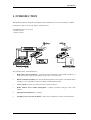
1. INTRODUCTION
The MR1200 modem is designed for half duplex data communication over a radio-frequency channel.
Connection is made to an external VHF or UHF transceiver.
The MR1200 exists in 2 versions:
- 1200 b/s version.
- 2400 b/s version.
The general features of the MR1200 are :
•
Half duplex data transmission : synchronous data transmission using FFSK modulation at
1200 b/s or 2400 b/s, plus data protection using an error correction code.
•
RS232 or RS485 serial link to the Data Terminal Equipment, with a choice of command modes
including 3-wire "automatic" mode (TxD, RxD, ground) in RS232 mode.
•
15-way sub-D connector for connection to the external transceiver .
•
Radio channel access conflict management : multiple equipment using the same radio
channel.
•
Microphone/loudspeaker set - optional.
•
Possibility exists to selectively address a radio relay conforming to CCIR or ZVEI standards.
ETIC - MR1200 - USER MANUAL - 908709-02
Page5
Introduction
•
Minimal power consumption of 50 mA, reduced to 300 µA using the power saving feature.
•
Durable and compact case housing the data handling/interface card.
•
Completely configurable from an ASCII terminal, using an elementary set of commands.
Page 6
ETIC - MR1200 - USER MANUAL - 908709-02
Installation
2. INSTALLATION
2.1.
Preamble
The MR1200 has an IP40 protection index. For outdoor installation therefore it will be necessary to
site the modem, transceiver, Data Terminal Equipment, battery and any temperature regulating devices
in a clean, dry enclosure.
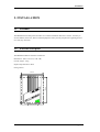
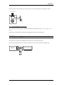
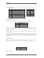
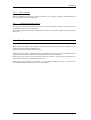
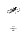
2.2.
External description
The MR1200 modem is housed in a metal box.
Dimensions: 180 x 130 x 45 (L x W x H)
Overall weight : 550 g
Impact and penetration : IP40
Fixing centres :
150 mm
120 mm
ETIC - MR1200 - USER MANUAL - 908709-02
Page7
Installation
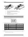
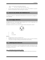
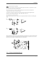
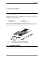
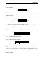
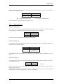
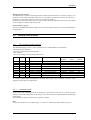
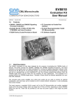
4
5
1
6
2
1:
2:
3:
Serial connector to data terminal (male 9-way sub-D).
Miniature push-button switch to enter configuration mode.
RS485 serial link or Microphone / loudspeaker connector, optional
(reference MIC-02)
Power indicator.
Radio transmission (TR) and reception (DP) indicators.
External transceiver connector (female 15-way sub-D).
Power connector (10 to 16 Volts).
4:
5:
6:
7:
2.3.
7
3
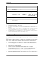
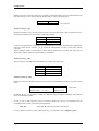
Connecting to the terminal
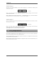
The MR1200 dialogues with its command terminal over an RS232 (+12V/ -12V) serial link. The
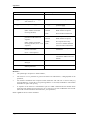
connector used is a male, 9-way sub-D whose pinout is as shown :
The different circuits carried on the interface are shown in the following table :
Pin
1
2
3
4
5
6
7
8
9
Circuit
Function
Usage according to control mode
automatic
direct
V25bis
109-DCD Detection of modulated carrier
optional
optional
optional
104-RxD Data reception
yes
yes
yes
103-TxD Data transmission
yes
yes
yes
108/2-DTR Wake-up / V25bis dialogue
optional
optional
yes
102-SG
Signal ground
yes
yes
yes
107-DSR Radio communication underway
optional
advised
yes
105-RTS Send command - in direct mode
yes
106-CTS Clear to send (flow control)
advised
yes
yes
125-RI
Received call indicator - V25bis mode
optional
optional
optional
Remarks :
•
Page 8
The command data terminal can be any type as long as its serial interface can function with the
following speeds and transmission formats :
ETIC - MR1200 - USER MANUAL - 908709-02
Installation
speed : 150, 300, 600, 1200, 2400, 4800 or 9600 bits/s
format :
•
7E1, 7O1, 7-2, 7E2, 7O2, 8-1, 8E1, 8O1, or 8-2
In practice, RS232 cables should be no longer than 15 metres. If the installation is exposed to
electrical or radio disturbance reduce cable lengths to a minimum.
2.4. Choice of radio channel data transmission rate
As standard, the modem uses a 1200 baud radio channel data rate. It can also be factory configured to
work at 2400 baud.
2.5.
Power supply connection
The MR1200 needs a d.c. power supply voltage of between 10.6 V et 15.8 V. When used on an
isolated site a 12V lead battery is an ideal solution.
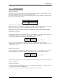
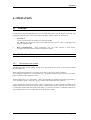
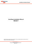
The MR1200 is fitted with a circular, male, power supply connector whose pinout is as shown :
1:
+12 V
2:
ground
3:
not connected
Remarks :
•
The MR1200 does not possess an ON/OFF switch.
•
The MR1200 works from a single source of power. Where two power sources are used (battery
+ solar panels, for example), switching between them must be done externally.
2.6.
Connecting to the transceiver
The MR1200 has been designed to be connected to different types of VHF or UHF transceivers (T/R).
Connecting to a T/R does, however, require level adjustments to be carried out, and sometimes changes
to be made to the circuit board.
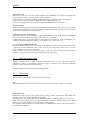
2.6.1.
Description of the LF interface signals
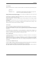
For the radio link the MR1200 uses a 15-way sub-D connector whose pinout is shown below:
ETIC - MR1200 - USER MANUAL - 908709-02
Page 9
Installation
8
15
9
11
10
1 (, 2, 3)
12
6
5
8
14
15
7
13
4
LFout
LFinLFin+
ALT
DP
VREG
GND
GND
+ 12 V
OV
: LF transmit output
: main LF receive input
: secondary LF receive input (for differential input mode)
: half duplex control
: radio carrier detect, or squelch inf. (optional)
: Output for T/R power supply relay control
: T/R signal ground
: T/R signal ground
(reserved for modem card power supply from the transceiver)
(reserved for modem card power supply from the transceiver)
: reserved
: reserved
: reserved
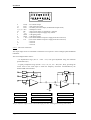
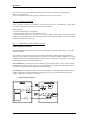
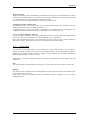
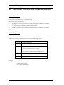
2.6.1.1. The LFout connection
The output stage levels are calculated to match the VCO input of a classic analogue phase modulated
transmitter.
The circuit diagram below shows :
- an amplification stage (IC3-A + R25 + P3) with gain adjustment using the multiturn
potentiometer (P3).
- a signal pre-emphasis stage (IC3-B + C17, C15, C3, C4 + R19, R11, R12), providing the
correct levels at the VCO input to obtain the frequency excursions recommended by the
ST/PAA/DIR/1382 standard.
-
VR
-
+
VR
VR
+
VR
modulating signal
radio frequency excursion
Tolerances
f0 = 1800 Hz
∆f0 = 1.57 kHz
+0.2 kHz / -0.32 kHz
f1 = 1200 Hz
∆f1 = 1.04 kHz
+0.13 kHz / -0.21 kHz
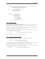
The pre-emphasis stage is in fact a 2nd-order high-pass filter defining the following relationship :
Page 10
ETIC - MR1200 - USER MANUAL - 908709-02
Installation
∆ f0
∆ f1 = 1.5 ± 0.12 kHz
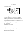
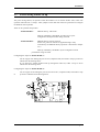
If the transmitter used has an input marked « external mic », it is quite likely that pre-emphasis is
already provided at the input stage. In this case, it is possible to bypass the modem pre-emphasis stage
by moving jumper S5 as shown below.
IC3
P3
S5
Potentiometer P3 then enables the level of the T/R input signal to be set so that the recommended
frequency excursions ∆f0 and ∆f1 can be obtained.
P3 is factory set for a signal of 175 mV r.m.s. at 1200 Hz, and 265 mV r.m.s. at 1800 Hz.
Depending on the type of microphone specified for the equipment, the T/R manufacturer may have
used filters having responses that could upset data transmission.
In this case, a complete transmitter frequency response spectrum will be required in order to determine
the characteristics of any compensating filter needed to obtain the recommended radio channel
frequency excursions. The discreet components around IC3-B may be changed to achieve the correct
filter response.
This is a delicate operation requiring radio frequency measuring equipment and an SMD soldering kit
(see ETIC).
2.6.1.2. The LFin connection
The demodulated signal input stage consists of :
- a passive band-pass filter (C12 + R8 + C14)
- an amplification stage(IC3-C + R4 + P1) with gain adjustment using the multiturn
potentiometer (P1).
The high input impedance means the LFin input stage will accept signals from the « audio » or
« external loudspeaker » outputs of most T/Rs.
Where the T/R has a differential output, the network (R9 + R10 + R15 + C9 + C15) allows such an
output to be connected. In this case strap S1 must be moved. Where possible, it is preferable to use the
differential mode configuration since it reduces noise.
ETIC - MR1200 - USER MANUAL - 908709-02
Page 11
Installation
S1
VR
10
BFin +
11
+
BFin -
-
P1
IC3
S1
The operation requires the copper track (component side) linking the S1 pins to be cut, and a strap
soldered in position as shown above.
P1 is factory set to give an RX level of 460 mV r.m.s. when a signal of 1500 Hz / 85 mV r.m.s. is
applied to the LFin input.
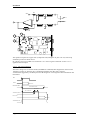
2.6.1.3. The ALT connection
The T/R 's change over to transmit mode (ALTERNAT command) either happens the instant circuit
105-RTS is set ON, or when the ALT command generated by the data card is asserted .
A monostable triggered by 105-RTS prevents T/R changeover occurring before data transmission has
terminated.
RTS
DATA
MONOSTABLE
monostable 100 ms
10 ms min
T1= 65 ms max
ALTERNAT Soft
DATA out
ALTERNAT E/R
Page 12
ETIC - MR1200 - USER MANUAL - 908709-02
Installation
2.6.1.4. The DP connection (optional)
In order to avoid collisions, the data card uses the DP signal (carrier detect, or squelch-inf.) to check
the radio channel status before transmitting data.
Not all T/Rs provide a carrier detect /squelch output signal, and in such cases the MR 1200
configuration need not take account of this input.
To generate its «Channel occupied» logic signal the modem compares the DP signal from the
transceiver with a threshold voltage (IC1 + R7 + R20 + R22 + P2 + C6).
The threshold level is adjusted with P2.
Using straps S3 and S4, a positive logic level can be generated whatever the nature of the DP signal
input.
S4
DP
Logic +
L5V
-
S3
+
S4
DP
Logic -
L5V
+
S3
Straps S3 and S4 are factory set for a positive DP signal. In the opposite case, straps S3 and S4 need to
be altered. Once the copper tracks (component side) connecting the S3 pins and those between the S4
pins have been cut, straps are soldered into position as shown below.
S3
P2
S4
2.6.2.
The type of connecting cable to use
ETIC - MR1200 - USER MANUAL - 908709-02
Page 13
Installation
The connection between the MR1200 and the transceiver must be made using a short length of
multicore screened cable.
The screen should be connected to the metal shell of the 15-way sub-D connector.
2.6.3.
Factory pre-setting
ETIC can deliver modems pre-configured for the chosen transceiver. Interconnection wiring sheets
have been produced for most models of transceiver on the market.
When ordering :
- specify the make and type of transmitter
- include the FR02 option in the order (modem set-up)
- if the transmitter details are not known to us, option FR03 should also be ordered (transmitter
connection investigation) and 2 units with manuals forwarded which will enable a connection and line
up adjustment sheet to be drawn up.
2.6.4.
Particularity of the 2400 b/s version
FFSK modulation at 2400 b/s
For FFSK modulation at 2400 b/s, the sub carriers coding bits 1 and 0 are respectively F1 = 1200 Hz
and F0 = 2400 Hz.
Now, 2400 b/s is at the limit of the transmission chain bandwidth, and any mismatching tolerable at
1200 b/s will now produce signal alterations too severe for the modem to handle. Furthermore, in order
to maintain the bit rate, modulation frequency shifts at crossover take place every quarter cycle, making
the modem more sensitive to signal phase errors.
For transmission : it is advisable to ensure that only one pre-emphasis filter is used : either by taking
the modem output directly to the T/R VCO, or by strapping out the modem filter and using the filter on
the transceiver microphone input (different modulation index),.
For reception : it is imperative to have access to the demodulator output signal directly before the deemphasis stage, thus avoiding the different LF stage filters in the receiver which alter the signal too
much to enable data reception to be error free.
Connection block diagram
Page 14
ETIC - MR1200 - USER MANUAL - 908709-02
Installation
2.7.
Power saving feature set up
The power saving feature, not operative when the modem is in its normal "awake" state, comes into
operation when the unit is "asleep". Three jumpers on the data card need to be positioned to configure
the different wake-up modes.
There are two possible sleep modes :
- SLEEP MODE 1 :
MR1200 asleep, T/R awake.
Wake up initiated by 108/2-DTR, by radio CD or by the
configuration mode push-button being activated.
- SLEEP MODE 2 :
MR1200 asleep, T/R not powered.
In this case, power for the T/R is supplied through a relay
controlled by the MR1200. Relay operation is described in chapter
4.5.3.
Wake up initiated by 108-DTR or by the configuration mode
push-button being activated.
Configuring the straps for SLEEP MODE 1 :
Cut the copper track linking the pins of S12 (component side) and solder a strap in position as
indicated on the drawing below.
If it is desired to confirm modem wake up through the radio CD, solder a strap on S2 as
indicated on the drawing below.
Configuring the straps for SLEEP MODE 2 :
in
Cut the copper tracks linking the pins of S12 and of S11 (component side) and solder a strap
position as indicated on the drawing below.
S2
S12
S11
ETIC - MR1200 - USER MANUAL - 908709-02
Page 15
Installation
2.8.
Connecting the optional microphone + loudspeaker set
A set compatible with the MR1200 is available, having reference MIC-02.
2.8.1. Description of the microphone/loudspeaker interface
The demodulated signal is amplified (circuit around IC3-D and IC5) in order to directly drive a 4 Ω
loudspeaker.
Warning : the LS output signal is referenced to +5V. The loudspeaker must therefore be connected
between the HP and V+ (+5V) outputs available on the female 9-way sub-D connector.
For a signal of 1500 Hz / 85 mV r.m.s. applied to the LFin input - (transceiver interface), the power
delivered to a 4 Ω LS is approximately 25 mW.
If the set used incorporates amplification (i.e. has a high impedance input), better audio quality can be
obtained by taking the LS signal directly from the output of IC3-D (behind C8), and if necessary
increasing the level by modifying the values of R3 and R17 (consult ETIC).
The pinout of the female 9-way sub-D connector is as shown :
1, 5 :
+5 V (cut when the MR1200 is in sleep mode)
2
:
LS output
3
:
microphone input
4
:
transmit control o/p (PTT: connected to pin 5 for transmit)
6
:
ground
7
:
D- RS485
8
:
RS485 Adaptation (to adapt impedance of the RS485 serial link by
connecting pin 7 to pin 8)
9
:
D+ RS485
The interface was designed for a particular microphone/LS set, for sale under reference «MIC-02».
Using another kind of set may necessitate modifications to some of the discreet components on the
card.
2.8.2. PTT connection (push to talk)
The MR 1200 needs a TTL logic signal to control the T/R changeover to transmission :
0V :
wait (reception)
+5V :
transmission
Page 16
ETIC - MR1200 - USER MANUAL - 908709-02
Installation
The PTT signal is derived simply by closing a pair of contacts operated by the changeover button :
Push to talk button
+5V
PTT
Board
2.8.3. MICROPHONE connection
The external microphone signal is amplified and filtered (low-pass filter, IC3-A + C18 + R21 + P3 +
C16).
If necessary, the signal level can altered by modifying resistor R21 (consult ETIC).
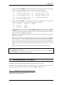
2.9. T/R power supply
The transceiver connected to the MR1200 should have an external power source.
For sleep mode operation the VREG output can then be used to control a T/R power supply relay.
RX
MR1200
GND
TX
TRANSCEIVER
Vreg
+V
ETIC - MR1200 - USER MANUAL - 908709-02
Page 17
Configuration
3. CONFIGURATION
3.1.
Entering configuration mode
Programming or listing the complete set of MR1200 operating parameters may be carried out using a
data terminal connected via the serial interface.
The terminal must be set up with the following communication parameters :
•
transmission speed
•
transmission data format
1200 bits/s
7E1 (7 bits, even parity, 1 stop)
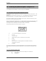
Once the terminal has been installed and the equipment powered, the operator pushes the
"CONFIGURATION" miniature push-button found on the modem front panel
At this point, any radio communication in progress will be terminated, indicators TR and DP will come
on and the following message will appear on the terminal screen : C >.
1
2
1:
2:
3.2.
Serial connector for terminal link (male 9-way sub-D)
Miniature push-button switch selects configuration mode
Configuration commands
Operating parameters and options are programmed into, and read from, the MR1200's E2PROM
memory using commands and responses as defined in the CCITT V25bis standard.
ETIC - MR1200 - USER MANUAL - 908709-02
Page19
Configuration
Terminal commands
###
< erroneous command >
Modem responses
INV
Command invalid
VAL
Command accepted
Read parameter ppp
LSPppp;vv...v
Indicates value
parameter ppp
RLP Pn
Read
page
n
of
the
configuration (n = 1 or 2).
LSPppp1;vv...v to
LSPpppn;vv...v
Indicates value vvv...v for
parameter ppp1 to pppn.
RES0
Reinitialise
dialogue
RES1
Reinitialise modem using the
default parameters
PRPppp;vv...v
Programme parameter
with value vv...v
RLPppp
ppp
vv...v
terminal-modem VAL
Reinitialisation carried out
VAL
Reinitialisation carried out
of
Remarks :
•
symbols shown by p represent ASCII numbers,
•
the value vv...v of a parameter is given in the form of an ASCII chain ; coding depends on the
parameter,
•
all terminal commands must be composed of ASCII characters and terminated by the control
code [Cr] (Carriage Return) or by the [Cr-Lf] (Carriage Return + Line Feed) combination,
•
The MR1200 echoes all the commands it receives on the terminal screen. It is always possible to
cancel this echo if the terminal echoes its keyboard input locally.
3.3.
Quick configuration
This paragraph describes the minimum configuration necessary to get the modem up and running
quickly.
When completed, the MR1200 will function in automatic mode (communication using 4 serial interface
circuits : 103-TD, 104-RD, 106-CTS and 102-SG). The power saving feature will not be operative.
•
Connect an ASCII terminal (type VT100, or a PC emulating VT100) to the MR1200 using a 4wire cable carrying circuits 103-TD, 104-RD, 106-CTS and 102-SG of the RS232 serial
interface.
•
Apply power to both terminal and modem.
•
Configure the terminal's communication port for 1200 bits/s, 7E1, no handshaking.
•
Operate the miniature push-button "CONFIGURATION" switch on the MR1200 front panel.
All modem indicators will then come on, and "C>" should appear on the terminal screen.
•
Enter the command "RES1" followed by [Cr]. The indicators should go out.
•
Operate the "CONFIGURATION" push-button switch once more to turn the indicator lamps on
again and bring back the "C>" cursor.
Page 20
ETIC - MR1200 - USER MANUAL - 908709-02
Configuration
•
•
Enter the command "PRP010;x" followed by [Cr], where x is a number between 0 and 8 coding
the data format that the MR1200 will use for communication with the terminal :
x=0 :
7E1 (7 bits, even parity, 1 stop)
x=5 :
8-1 (8 bits, no parity, 1 stop)
x=1 :
7O1 (7 bits, even parity, 1 stop)
x=6 :
8E1 (8 bits, even parity, 1 stop)
x=2 :
7-2 (7 bits, no parity, 2 stops)
x=7 :
8O1 (8 bits, even parity, 1 stop)
x=3 :
7E2 (7 bits, even parity, 2 stops)
x=8 :
8-2 (8 bits, no parity, 2 stops)
x=4 :
7O2 (7 bits, even parity, 2 stops)
Enter the command "PRP011;y" followed by [Cr], where y is a number between 0 and 6 coding
the data rate the MR1200 will use for communication with the terminal :
y=0 :
150 b/s y=3 :
1200 b/s y=6 :
y=1 :
300 b/s y=4 :
2400 b/s
y=2 :
600 b/s y=5 :
4800 b/s
9600 b/s
•
If the MR1200 is to be used to transmit MODBUS/JBUS frames, enter the command
"PRP030;1" followed by [Cr]. Now, use the "RLP53" command followed by [Cr] to check that
when receiving data, the wait time is sufficiently long so as to not strip off these frames and thus
inhibit block mode : "LSP53;5" (minimum).
•
Operating the "CONFIGURATION" push-button one last time will turn off the indicators and
disconnect the terminal.
•
Connect the modem to one of the DTEs that will be using radio communication. The MR1200
will work with a 4-wire cable carrying the RS232 serial interface circuits 103-TD, 104-RD and
02-SG. A wire for the 106-CTS signal is optional - the modem uses this circuit for handshaking.
Check which DTE serial interface loops are necessary for it to function correctly : most PCs, for
example, require a loop between the 107-DSR and 08-DTR lines, plus the 106-CTS circuit to be
wired.
•
Prepare and install the other radio modems in the same way before running the application.
To read a modem's configuration quickly, use the "RLP P1" and "RLP P2" commands to provide a
two-page listing of the settings.
Once configured, it is advisable to write down the modem settings in the "MODEM
CONFIGURATION" table provided in the appendix.
3.4.
Operating parameters and options
The following paragraphs describe the MR1200 configuration parameters in detail.
The default values for MR1200 parameters and options have a * next to them. These are the values
assigned when the modem is first switched on or when the "RES1" command is sent.
3.4.1.
Configuring the terminal-modem interface
Parameters 010 [f_v24] and 011 [v_v24]
ETIC - MR1200 - USER MANUAL - 908709-02
Page 21
Configuration
These set the speed and data format of the terminal-modem serial link for normal operation (i.e. other
than configuration mode).
f_v24
0*
1
2
3
4
5
6
7
8
format
(7 bits, even parity, 1 stop)
(7 bits, even parity, 1 stop)
(7 bits, no parity, 2 stops)
(7 bits, even parity, 2 stops)
(7 bits, even parity, 2 stops)
(8 bits, no parity, 1 stop)
(8 bits, even parity, 1 stop)
(8 bits, even parity, 1 stop)
(8 bits, no parity, 2 stops)
7E1
7O1
7-2
7E2
7O2
8-1
8E1
8O1
8-2
v_v24
0
1
2
3*
4
5
6
speed
150 b/s
300 b/s
600 b/s
1200 b/s
2400 b/s
4800 b/s
9600 b/s
Parameter 012 [mod_ter]
Defines the MR1200 control mode used for normal operation, from the 4 possible modes :
mod_ter
0
1*
2
3
control mode
marked automatic
simple automatic
direct
V25bis
Either of the "automatic" modes is adequate in most instances, having been designed to allow the
modem to operate transparently using only circuits 103-TD and 104-RD (and 106-CTS for
handshaking if required).
In "direct" mode, the terminal uses an extra circuit (105-RTS) to control access to the radio channel
before sending data.
The "V25bis" control mode uses all the serial interface signals - except 105-RTS - to give the terminal
total control of the modem through a set of commands and responses corresponding to the V25bis
standard. Where a number of radio modems are networked, individually addressed data messages can
also be sent.
Parameter 013 [echo]
Enables or cancels the echoing of configuration commands (PRP/RLP) on the terminal screen. If the
terminal already has local keyboard echo, it is advisable to set the value of this parameter to 0.
echo
0
1*
config. echo
no
yes
Parameter 014 [mark]
Page 22
ETIC - MR1200 - USER MANUAL - 908709-02
Configuration
Defines the ASCII control code for the character used to control data transmission in marked automatic
mode (see chapter 4):
mark
from 0 to 255
format
BCD
* 013
A value of 013 is used to start transmission of a line of characters on reception of the [Cr] (Carriage
Return) control character.
Parameter 015 [error]
When not null, the error parameter determines the code of the ASCII character sent to the terminal
signalling reception over the radio channel of an invalid frame :
error
from 0 to 255
format
BCD
* 000
000 = used to cancel the signalling of invalid frames
Note: Should interference occur on the radio channel while the modems are synchronising, several
frames may be lost without this fact being signalled to the terminal.
Parameter 016 [ges_dsr]
With this parameter set to 1, the RS232 interface 107-DSR circuit is implemented as per a standard
telephone line modem : 107-DSR is ON during communication (radio channel), and OFF when at rest.
Setting its value to 0 forces 107-DSR to the permanently ON condition.
ges_dsr
0
1*
3.4.2.
107-DSR handling
no (permanently ON)
yes (ON in communication)
Configuring the radio interface
Parameter 020 [mod_rad]
Defines the MR1200 data transmission mode :
mod_rad
0
1*
transmission mode
simple mode(no CRC)
basic mode (with CRC)
Modem transmission normally operates in basic mode : the data is formatted into frames protected by
the addition of a cyclic redundancy check code (CRC), resulting in a useful radio channel data rate of
900 b/s.
Simple mode should only be used over a good quality radio link (communicating stations relatively
close) and when it is essential to have a useful radio channel data rate greater than 900 b/s. Data is
transmitted with no extra coding and any errors are no longer filtered on reception.
Parameter 021 [tp_alt]
ETIC - MR1200 - USER MANUAL - 908709-02
Page 23
Configuration
When the transceiver has been instructed to transmit, an initial time delay may be introduced before the
first data message is sent, thereby allowing the RF stages to achieve nominal power :
tp_alt
from 0 to 255
units
x 10 ms
* 30 (=300 ms)
Parameter 022 [ges_dp]
Determines whether or not the carrier detect signal is used. The DP signal is derived from the receiver
RF stages and indicates the current status of the radio channel :
ges_dp
0*
1
DP implemented
no
yes
In the case of applications comprising several modems likely to transmit simultaneously (multi-master
network, random access network), ges_dp should be implemented in order to limit radio channel
collisions.
Where exchange of data is controlled by a master station (master-slaves network), this option may be
deselected to reduce modem turn-around delay to a minimum.
Parameter 023 [st_num]
Allows selection of the MR1200 CCIR/ZVEI tone encoder operating mode :
st_num
0*
1
2
3
standard
CCIR
CCIR short
ZVEI 1
ZVEI 2
Parameter 024 [seq_num]
Defines the tones to be emitted and/or the protocol used by the MR1200 each time it goes into transmit
mode :
seq_num
Tone codes: '0' to '9', 'A' to 'E'
Control codes: ': ? #> ! W ,'
format
Chain of 10
characters max.
* null chain
By default, the seq_num parameter is empty, the MR1200 simply testing the availability of the channel
before transmitting any data.
In order to turn on and control the carrier of a CCIR or ZVEI relay, the seq_num parameter must be
programmed with a chain of characters having the form :
'?nn...n#>'
where nn...n is the relay's selective call number.
For more details on character chain coding for the seq_num parameter refer to chapter 4 (§4.4).
Page 24
ETIC - MR1200 - USER MANUAL - 908709-02
Configuration
3.4.3.
Operating parameter
Parameter 030 [bloc]
For normal operation the block option is deselected, data being passed on to the terminal as soon as it
has been extracted from the frames received over the radio link.
In block mode, data is stored until a complete message has been received, whereupon a block of data is
passed on in an uninterrupted stream.
bloc
0*
1
block mode
no
yes
Normal mode is the quicker option for modem to terminal data handling.
However, subject to testing, block mode may be selected when the terminal needs to have data
presented in a continuous stream (as with MODBUS/JBUS data frames, for example).
Block mode is only possible when the modem is configured for 2400 b/s radio channel working.
Parameter 031 [ad_mod]
Each MR1200 modem on a transmission network can individually receive data by being allocated a
unique address, notably when the "V25bis" control mode is used (see chapter 4).
The ad_mod parameter represents the individual modem's address :
ad_mod
from 0 to 255
format
BCD
* 0 (no address)
If 0 is entered for this parameter the MR1200 will not use an address when it transmits data.
To address data to stations within a transmission network, enter different, non zero addresses for each
communicating station.
Parameter 032 [ad_dest]
Where a modem has been allocated an address (ad_mod parameter), the parameter ad_dest may be
used to address data to a destination modem, when automatic or direct control mode has been set :
ad_dest
from 0 to 255
format
BCD
* 0 (no address)
If either the ad_mod parameter is null, or V25bis control mode is being used, the value of the ad_dest
parameter is ignored.
Parameter 033 [phonie]
An optional microphone/loudspeaker set can be connected to the MR1200 for combined data and
speech transmission working (see chapter 2).
In such a case, the phonie option must be enabled. Otherwise it is best to inhibit it :
ETIC - MR1200 - USER MANUAL - 908709-02
Page 25
Configuration
phonie
0
1*
speech transmission
Inhibited
Enabled
Parameter 034 [f_paq]
f_paq sets the maximum data packet size the MR1200 will transmit. The value set determines the
frequency of the re-synchronisation sequences exchanged between the communicating modems (see
chapter 4) :
f_paq
0
1
2
3
4
5
6*
7
8
9
10
packet format
12 bytes
24 bytes
48 bytes
72 bytes
96 bytes
120 bytes
144 bytes
168 bytes
192 bytes
216 bytes
240 bytes
Select a small packet size (48 bytes or less) if transmission conditions are only mediocre.
Select a larger size (144 bytes or more) if the radio link is of good quality and the data rate needs to be
high.
Parameter 035 [f_mem]
Alters the MR1200's transmit data buffer size from 32 bytes to 2 Kbytes depending on the application:
f_mem
0
1
2
3*
4
5
6
3.4.4.
buffer capacity
32 bytes
64 bytes
128 bytes
256 bytes
512 bytes
1024 bytes
2048 bytes
Power saving feature
Parameter 043 [att_ina]
Page 26
ETIC - MR1200 - USER MANUAL - 908709-02
Configuration
This parameter determines the length of time after which the MR1200 goes to sleep once transmission
and reception of data has ceased :
att_ina
de 0001 to 6000
0000 *
format
MMSS
unlimited wait
MM : minutes (2 ASCII numbers)
SS : seconds (2 ASCII numbers)
The value 0000 prevents the modem from going to sleep.
3.4.5.
Other parameters
Parameter 050 [tp_emi]
Fixes a limit to the length of the MR1200's transmission time, serving to avoid both a modem
monopolising the radio channel and the risk of transceiver RF stages overheating :
tp_emi
from 1 to 255
0*
units
x1s
no limit
A value of 0 removes all limits on the duration of transmission.
Parameter 051 [tp_sil]
A minimum period of post transmission silence can be defined, to allow other MR1200 modems the
time to access to the radio channel :
tp_sil
de 1 to 255
0*
units
x1s
= 6/20 x duration of
transmission
The MR1200 ignores this parameter if no transmission time limit has been set (parameter tp_emi =
null).
Parameter 052 [tp_ae]
Corresponds to the length of time the MR1200 will wait before ending radio transmission, once there is
no more data to be sent :
units
tp_ae
de 0 to 255
x 20 ms
* 1 (=20 ms)
Enter a low value (20 ms) where applications function by a rapid exchange of data with brief
request/response intervals.
Enter a higher value (100 ms or more) where : - data messages are long ; the control terminal's
transmission speed is less than 2400 bits/s ; data flow is irregular.
ETIC - MR1200 - USER MANUAL - 908709-02
Page 27
Configuration
Parameter 053 [tp_ar]
Represents the minimum MR1200 wait time before changeover to transmission, following radio
channel data reception :
tp_ar
de 0 to 255
units
x 20 ms
* 1 (=20 ms)
Enter a low value (20 ms) where applications function by a rapid exchange of data with brief
request/response intervals.
Enter a higher value (100 ms or more) where : - data messages are long ; the control terminal's
transmission data rate is less than 2400 bits/s ; the flow of data is irregular
Parameter 054 [tp_rc]
Defines the MR1200 wait time before terminating the current communication in the absence of either
data being sent or received :
tp_rc
de 0 to 999
units
x 50 ms
* 2 (=100 ms)
Enter a low value (100 ms) where applications function by a rapid exchange of data with brief
request/response intervals, in automatic or direct control mode.
Enter a higher value (1 s or more) in V25bis control mode.
3.5.
Leaving configuration mode
Once modem configuration has been completed, the operator activates the miniature push-button
switch a second time to return the unit to normal operation.
The TR and DP indicators go out, and the modem serial interface is reconfigured with the speed and
format parameters set by the operator.
Note : Should the operator leave the MR1200 in configuration mode, the unit will automatically revert
to normal operation after 5 minutes.
Page 28
ETIC - MR1200 - USER MANUAL - 908709-02
Operation
4. OPERATION
4.1.
Principle
Communication between MR1200 and control terminal takes place over the RS232 serial link. The
modem then obtains access to the radio channel and finally sends the data to be transmitted.
•
Call control :
4 control modes enable the terminal to control the modem.
The MR1200 then checks the status of the radio channel, turns on a relay if appropriate and
finally transmits the data.
•
Data Communication : Data transmission over the radio channel is half duplex.
Communication between the modem and terminal is duplex.
4.2.
4.2.1.
Radio channel
Data transmission method
The MR1200 radio modem adheres strictly to the specifications laid down in the French standard
ST/PAA/DIR/1382.
Radio channel data transmission is synchronous and uses a data rate of 1200 or 2400 b/s.
The modulation employed is of an indirect type : an FFSK modulated audio frequency sub-carrier
phase modulates a radio frequency carrier.
Normal transmission is in « base mode » : data to be transmitted is formatted into frames protected by a
cyclic redundancy check code (CRC), giving a useful radio channel data rate of 900 b/s.
Another transmission mode without CRC, called « simple mode », is also available but should not be
employed unless the radio link is of good quality (communicating stations relatively close), and where
a useful radio channel data rate greater than 900 b/s is essential. The data is transmitted without any
extra coding and errors are no longer filtered out on reception of data.
ETIC - MR1200 - USER MANUAL - 908709-02
Page29
Operation
4.2.2.
Format and coding
The MR1200 assembles the data sent by its control terminal into packets of varying size depending on
the amount of data.
The packets are themselves sub-divided into 64 bit frames, of which 16 bits are used for the cyclic
redundancy check code (CRC) when in « base mode ».
Before being transmitted each packet is preceded by a sequence of bits whose job is to synchronise the
two modems (SYNC).
4.2.3.
Operating conditions
radio channel access
At rest, the MR1200 permanently checks for activity on the radio channel ; a transmit command may
simply be refused if the channel is occupied (absence of carrier for at least 0.1 seconds).
Half duplex timing
When transmission begins the MR1200 systematically delays sending the first data in order to allow
transceiver RF stages to develop full power (tp_alt parameter).
Data packet size
Reducing or increasing data packet size will force the communicating modems to re-synchronise, the
frequency depending on the application and the quality of the radio link (f_paq parameter).
Half duplex transmission
The MR1200 control of T/R switching (half duplex) is transparent to the terminal. The use of buffers
enables terminal-modem dialogue to remain duplex throughout.
The modem will switch from transmission to reception according to a configurable timing parameter
(tp_ae parameter), when there is no more data to be sent.
The MR1200 stays in the receive state while data is incoming, reverting to transmission at the end of a
second configurable time delay if the terminal has new data (tp_ar parameter).
Received data restoration and error treatment (base mode)
The CRC of each frame received is tested, and frames with CRC errors are either eliminated or
signalled using a configurable character (error parameter). The MR1200 extracts the data from each
error-free frame, placing the bytes end to end.
The data is re-transmitted to the terminal either as it arrives, or as a block of data once the last frame
has been received and restored (" block mode " option, bloc parameter).
Page 30
ETIC - MR1200 - USER MANUAL - 908709-02
Operation
Duration of data emission
The MR1200 will continue transmitting data for a limited period of between 1 and 255 seconds (tp_emi
parameter), after which the modem will pause for a period also of between 1 and 255 seconds (tp_rec
parameter) to allow other modems to gain access to the radio channel.
If transmission time limits have been set, long messages should be segmented and sent by the terminal
in several batches, otherwise data may be lost.
modem memory capacity
The size of the MR1200's transmit buffer can be increased from 32 bytes up to 2 Kbytes depending on
the application.
4.3.
Modem control modes
4.3.1.
The terminal-modem interface
The MR1200 dialogues with its control terminal across a standard RS232 serial interface.
The following table describes :
- the circuits comprising the serial interface
- their function
- their use according to the operating mode chosen.
Circuit
Name
Pin
Direction
Function
102
103
104
105
106
107
108/2
109
125
SG
TD
RD
RTS
CTS
DSR
DTR
DCD
RI
5
3
2
7
8
6
4
1
9
terminal->modem
modem->terminal
terminal->modem
modem->terminal
modem->terminal
terminal->modem
modem->terminal
modem->terminal
Signal ground
Transmitted data
Received data
Ready to send
Clear to send
Data set ready
Data terminal ready
Carrier detect
Ring indicator
Control mode / implementation
automatic
direct
V25bis
yes
yes
yes
yes
yes
yes
yes
yes
yes
yes
advised
yes
yes
optional
advised
yes
optional
optional
yes
optional
optional
optional
optional
optional
optional
Its 4 control modes enable the MR1200 to be used with a large range of terminals making it easily
adaptable to particular user applications.
4.3.2.
Automatic mode
In this mode, radio modem operation is transparent to the terminal, with only the 3 circuits 103-TD,
104-RD, and 102-SG being used. If necessary circuit 106-CTS may be implemented for handshaking
requirements.
Data transmission begins on detection of a specific character.
Rest
Circuit 106-CTS has an ON condition (logic 1), and circuit 109-DCD an OFF condition (logic 0).
ETIC - MR1200 - USER MANUAL - 908709-02
Page 31
Operation
Data transmission
When there is data to be sent the terminal transmits it to the MR1200. On reception of the first data
byte an attempt is made to access the radio channel (see § 4.4).
If transmission is momentarily inhibited, the MR1200 will delay data output for several seconds.
If radio channel access is refused (see §4.4) the data sent by the terminal is lost.
Otherwise, having gained access to the radio channel the MR1200 begins to send data.
Reception of data
When not transmitting data, the MR1200 is permanently listening out for radio channel activity. If data
is detected, the modem informs the terminal using the 109-DCD line before passing it on. The terminal
cannot refuse communication with the modem.
Termination of radio communication
When data transfer has been concluded - no data awaiting transmission or being received - the MR1200
returns to its rest state after a pre-configured time delay (tp_rc parameter).
Communication may, on the other hand, be interrupted by the modem to avoid exceeding the preconfigured maximum transmission time (tp_emi parameter), if a value has been set.
Use of circuits 107-DSR and 106-CTS
Circuit 107-DSR normally has an ON condition set during the period of radio data transfer, and an OFF
condition set when communication has ended. However, the configuration option exists to set this
circuit permanently ON (ges_dsr parameter).
Circuit 106-CTS is ON most of the time, being set OFF only when the data transmission buffer
overflows. The signal may be used to control data flow from the terminal.
4.3.3.
Marked automatic mode
"Marked automatic" mode is simply a variant of automatic mode, the only difference being with
transmission control : in this mode, transmission begins on detection of a particular pre-defined
character used to end all files to be transmitted.
The ASCII character code is configurable (mark parameter).
4.3.4.
Direct mode
In direct mode, transmission is controlled using the RTS signal.
Rest
The terminal holds OFF circuit 105-RTS (logic 0). Circuits 106-CTS and 109-DCD are both OFF.
Data transmission
When there is data to be sent, the terminal begins by setting ON the 105-RTS line. The modem then
attempts to gain access to the radio channel (see § 4.4).
If transmission is momentarily inhibited, the MR1200 will delay outputting data for several seconds.
Radio channel access may, however, be refused (see § 4.4): in this case, 106-CTS remains OFF, but the
terminal can maintain 105-RTS ON in readiness for another attempt.
Having finally obtained access to the radio channel, the MR1200 sets ON line 106-CTS, authorising
the terminal to send its data.
Page 32
ETIC - MR1200 - USER MANUAL - 908709-02
Operation
Reception of data
When not transmitting data, the MR1200 is permanently listening out for radio channel activity. If data
is detected, the modem informs the terminal by setting ON the 109-DCD line, before passing the data
on. The terminal cannot refuse communication with the modem..
Line 106-CTS is also set ON enabling the terminal to reply with its data.
Termination of radio communication
The MR1200 returns to its rest state after the pre-configured time delay, once 105-RTS is set OFF
AND data transfer has been concluded (parameter tp_rc).
Communication may, on the other hand, be interrupted by the modem to avoid exceeding the preconfigured maximum transmission time (tp_emi parameter), if a value has been set.
Use of circuits 107-DSR and 106-CTS
Circuit 107-DSR is normally set ON during radio data transmission and set OFF when communication
ends. It can, however, be configured to be ON permanently (ges_dsr parameter).
Once radio transmission has begun, 107-CTS remains ON and is only set OFF to signal transmission
data buffer overflow. The signal can be used to control data flow from the terminal.
4.3.5.
V25bis mode
The "V25bis" control mode makes a more extensive use of the serial interface - only 105-RTS is
unused - giving the terminal total control over the modem through a set of commands and responses
defined by the V25bis standard. Where a number of radio modems are networked, individually
addressed data messages can also be sent out.
Each modem is allocated a number between 001 and 255 constituting its network address (ad_mod
parameter).
Rest
The terminal holds the 108/2-DTR line OFF (logic 0). Circuits 106-CTS and 109-DCD are also OFF.
Dialogue
The terminal opens communication with the MR1200 by setting ON 108/2-DTR. The modem replies
by setting ON circuit 106-CTS.
Under these conditions the MR1200 waits for commands and gives responses as per the V25bis
standard (CCITT).
ETIC - MR1200 - USER MANUAL - 908709-02
Page 33
Operation
Terminal commands
###
< Erroneous command >
Modem responses
INV
Command invalid
PRPppp;vv...v
Programme parameter ppp
with value vv...v
VAL
Command accepted
RLPppp
Read parameter ppp
LSPppp;vv...v
Indicates the value vv...v of
parameter ppp
CRNaaa
Transmit command
DLCxx
Call delayed xx seconds
(aaa = address of modem
receiving the data)
CFIAB
Radio channel occupied
CNX
Start of radio transmission
Transmit command with a
particular CCIR/ZVEI call
sequence
DLCxx
Call delayed xx seconds
CFIAB
Radio channel occupied
CFIRT
No response from relay
CNX
Access to channel obtained
(Start of radio transmission)
CNX
Transmission of sequence
terminated
<Modem at rest>
INC
Detection of a radio
transmission addressed to the
modem
RES0
Reinitialise terminal-modem
dialogue
VAL
Reinitialisation carried out
RES1
Reinitialise modem with
default parameters
VAL
Reinitialisation carried out
CRNaaa/ss...s
(aaa = address of modem
receiving the data, ss...s = call
sequence)
CRN/ss...s
CCIR/ZVEI call sequence
transmit command
(ss...s = call sequence)
Remarks :
•
The symbols p or a represent ASCII numbers,
•
The value vv...v of a parameter is given in the form of an ASCII chain ; coding depends on the
parameter,
•
All terminal commands must comprise ASCII characters and end with a control code [Cr]
(Carriage Return), or with the [Cr-Lf] (Carriage Return + Line Feed) combination. The modem
terminates its replies with [Cr-Lf],
•
A sequence of the form ss...s transmitted as part of a CRN command tells the modem which
particular radio channel access protocol to use, as well as to activate CCIR/ZVEI tone encoder
(the CCIR or ZVEI standard is selected with st_num parameter).
Refer to § 4.4 for the use of this command.
Page 34
ETIC - MR1200 - USER MANUAL - 908709-02
Operation
Call command
When the terminal wishes to send data it sends the modem a call command having the following syntax
:
CRNaaa [Cr]
or
CRNaaa/ss...s [Cr]
where aaa is the network address of the modem receiving the data
and ss...s is an optional CCIR/ZVEI call sequence.
If the command sent is incorrect the reply is : INV. Otherwise, the MR1200 sets ON 106-CTS, and
attempts to access the radio channel (see §4.4).
If transmission is momentarily inhibited, the MR1200 sends a delayed call response to the terminal :
DLCxx, where xx is the wait time in seconds.
If access to the channel is refused, the MR1200 replies with the appropriate error message (see §4.4):
CFIAB or CFIRT.
The terminal can itself cancel the current call command by setting 108/2-DTR to OFF (modem returns
to rest state).
When it finally gains access to the channel, the MR1200 lets the terminal know by sending : CNX.
Then, 106-CTS is set ON to allow the terminal to send data.
Call reception
When not transmitting, the MR1200 permanently monitors radio channel activity.
If it detects incoming data when in the rest state, it simultaneously sets ON 125-RI and 109-CD. The
terminal then has 6 seconds to accept the call by setting ON 108/2-DTR, otherwise any incoming data
will be lost.
If the terminal sets ON 108/2-DTR, or if data communication is detected when a dialogue is in
progress, the MR1200 sets OFF 125-RI and sends an incoming call message to the terminal : INC.
106-CTS is then set ON to allow the terminal to communicate its data.
End of communication
Communication ends with the timing as configured (tp_rc parameter), once there is no more data to
send or being received.
Alternatively, the modem may interrupt communication to avoid exceeding the pre-configured
maximum transmission time (tp_emi parameter), or the terminal may do so by setting OFF 108/2-DTR.
Whatever the case, the MR1200 returns to either a rest or dialogue state depending on the condition of
108/2-DTR.
Use of circuits 107-DSR and 106-CTS
Circuit 107-DSR is normally set ON during radio data transmission and set OFF when communication
ends. It can, however, be configured to be ON permanently (ges_dsr parameter).
Once radio transmission has begun, 106-CTS remains ON and is only set OFF to signal transmission
data buffer overflow. It can be used to control the flow of data from the terminal.
ETIC - MR1200 - USER MANUAL - 908709-02
Page 35
Operation
4.4.
Radio channel access, & use of the CCIR/ZVEI tone dialler
4.4.1.
Introduction
Two elements comprise the MR1200 "tone dialling" system : the radio carrier detection circuitry and a
tone encoder conforming to CCIR or ZVEI standards.
This system can be programmed to :
•
operate and control carrier activation of a relay conforming to CCIR or ZVEI standards,
•
call paging devices conforming to CCIR or ZVEI standards,
•
or simply test radio channel availability before transmission in order to avoid collisions,
•
.../...
4.4.2.
Programming
The choice between CCIR or ZVEI mode is programmable (st_num parameter).
The tones to transmit and/or the radio channel access code are defined in a call sequence comprising a
chain of up to 10(max.) ASCII characters chosen from the following symbols :
'0' to '9'
'A' to 'E'
':'
'#'
'?'
'>'
'!'
','
'W'
transmit corresponding tone.
(CCIR or ZVEI mode)
test for channel availability.
(no radio carrier wait time - 6s max.)
test relay carrier activation, follows sequence sent if
carrier present.
(radio carrier present wait time - 6s max.)
deactivate half duplex then test for presence of relay
carrier. Follows sequence sent if carrier absent. (see
examples below)
enable transmission
disable transmission (receive)
short pause (100 ms)
long pause (2 s)
Examples:
':>'
Page 36
wait for channel to become free (6s max.),
if channel free - transmit,
if not - report CFIAB failure.
ETIC - MR1200 - USER MANUAL - 908709-02
Operation
':122W33!'
wait for channel to become free(6s max.), if not - report CFIAB failure,
transmit tone sequence '122', then pause for 2s,
transmit tone sequence '33', then return to rest state.
4.4.3.
'#>'
test for relay carrier (6s max.),
if carrier present -transmit,
if not - report CFIRT failure.
'?1A22#>'
test for relay carrier,
if absence of carrier detected,
transmit '1A22' ,
test for relay carrier,
if relay carrier present
transmission,
if not - report CFIRT failure,
if not transmit immediately.
Radio relay control
At each switch over to transmission during radio communication the MR1200 CCIR/ZVEI tone
dialling system can be activated using a call command.
For this, the seq_num parameter simply needs to be programmed with the appropriate call sequence.
By default this parameter is null, the MR1200 using its carrier detect facility to check channel
availability each time before it transmits (similar to a ':>' sequence).
To activate and control a CCIR or ZVEI relay carrier, the seq_num parameter must be programmed
with a sequence respecting the following syntax :
'?nn...n#>'
where nn...n is the selective call number of the relay.
CCIR or ZVEI mode is selected by the st_num parameter value.
4.4.4.
Usage in a V25bis call command
In V25bis mode, the terminal can place a particular call sequence in the call command :
CRNaaa/ss...s
where aaa is a radio modem network address
and ss...s is the call sequence to use.
This sequence is then only used by the MR1200 at the beginning of transmission. Once communication
has been established the call sequence is that programmed in the seq_num parameter.
Equally, the terminal can transmit a call sequence for the MR1200 to execute without there being any
subsequent data (CCIR or ZVEI pager calling). The syntax is then:
CRN/ss...s
where ss...s is the call sequence to execute.
ETIC - MR1200 - USER MANUAL - 908709-02
Page 37
Operation
4.5.
Power supply saving (sleep mode)
4.5.1.
Operation
The MR1200 is equipped with a power saving system that deactivates particular modem functions
during periods of complete inactivity, in order to reduce power consumption to a minimum (300µA).
The functions are reactivated when one of the following events occurs :
•
terminal sends a command (circuit 108/2-DTR set ON),
•
radio channel activity (carrier detected),
•
modem first powered, or re-powered after a loss of supply,
•
operation of the configuration button.
Note : the sleep mode chosen is set by straps on the circuit board.
4.5.2.
Sleep mode
When inactive, the MR1200 drops into sleep mode after a configurable time delay of between 1 second
and 60 minutes (att_ina parameter).
If one of the above events occurs before the time-out, the modem remains awake and the countdown is
stopped..
Note : The att_ina parameter can be forced to 0 : in this case the power saving feature in inoperative.
4.5.3.
Transceiver wake up
The transceiver's power supply can be relay controlled using the MR1200 VREG output.
When the MR1200 drops into sleep mode the VREG signal disconnects the transceiver power supply.
RX
MR1200
GND
TX
Transceiver
Vreg
+V
Page 38
ETIC - MR1200 - USER MANUAL - 908709-02
Operation
4.5.4.
Power up state
When the MR1200 is first powered, or repowered after a loss of supply, it remains awake until after the
first radio communication has taken place.
4.5.5.
Configuration mode wake up
Operating the configuration push-button switch will cause the modem to wake up so that its different
operating parameters can be programmed.
On leaving configuration mode, the modem remains awake until after the first radio communication has
taken place.
4.6.
Speech use
Where applications use the radio channel for both speech and data communication the MR1200 can be
equipped with a microphone/loudspeaker set.
In this case, the phonie option must be selected.
When the operator wishes to speak he pushes the transmit-receive button on the set. The MR1200 then
suspends all current data communication, and switches the T/R into transmission.
Holding the button down and using the microphone the operator's speech will be transmitted, any
request from the terminal to send data being ignored.
Releasing the button switches the T/R back to receive mode, enabling the operator to listen to his
correspondent and data communication to be re-established.
ETIC - MR1200 - USER MANUAL - 908709-02
Page 39