1
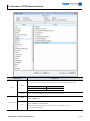
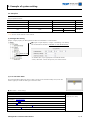
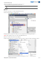
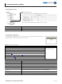
SIEMENS AG.
SIMETIC S7-1200 Series
ETHERNET(OP Communication) Driver
Support version
OS
V3.0
XDesignerPlus
2.6.34.0
Introduction
Please read this manual carefully to know connection methods
and procedures of “TOP to External device
1. System configuration
Page 2
A section for showing connectable external devices, serial signal
types, connection configurations. Refer this section to select the
right system configuration .
2. Selection of TOP, External device
Page 3
A section for selecting a Top model and the external device .
3. Example of system setting
Page 4
A section for explaining examples to connect communications of
TOP to External Device.
Select the correct example in your case according to “1. System
configuration .
4. Communication setting
Page 6
A section for Communication setting.
The setting should be the same with the external device .
5. Usable address
Page 8
A section for usable address to communicate with external
device .
XDesignerPlus Communication Manual
1/9
1. System configuration
System configuration of TOP and “SIEMENS AG – SIEMETIC S7 1200 Ethernet Series”.
Series
SIMATIC
S7-1200
CPU
CPU1211C
CPU1212C
CPU1214C
Link I/F
Comm. type
PROFINET
Ethernet
Interface on CPU
TCP
System setting
3.1 Setting Example 1
( Page 4 )
Cable
Twisted Pair Cable*Note1)
*Note1) Twisted Pair Cable
- STP(Shield Twisted Pair Cable) or UTP(Unshield Twisted Pair Cable) category 3, 4, 5.
- Connection to Herb, Trans receiver is available, and must use direct cable for this configuration.
■ Connection configuration ( TOP number : External number )
ㆍ1 : 1(TOP 1 unit to External device 1 unit) connection
ㆍ1 : N(TOP 1 unit to External device several units) connection
XDesignerPlus Communication Manual
2/9
2. Selection of TOP, External device
Select a external device which is communicated to the TOP.
Setting Items
Description
Select a TOP series which is communicated with external device.
Install an OS file v3.1 as diagram below before download a project file you have made.
Series
TOP
Name
Vendor
.
Series
OS Version
XTOP / HTOP
V3.1
Select a TOP model which is communicated with external device.
Select vendor of the external device which is communicated with TOP.
Select “SIEMENS AG.”.
Select a model name of the external device which is communicated with TOP.
External Device
PLC
Select “SIEMENS S7-1200 ETHERNET”.
Check whether the external device you want to use is connectable or not
in “1. System configuration.
XDesignerPlus Communication Manual
3/9
3. Example of system setting
Set Communication interface of TOP and external device as below.
3.1 Example 1
Set your system as below.
Set Name
TOP
S7 1200 Series
Note
IP Address*Note1)Note2)
192.168.0.50
192.168.0.51
User Set
Subnet Mask
255.255.255.0
255.255.255.0
User Set
Protocol
TCP
Port
2000
TCP
User Set
Read Port
102
Write Port
102
User Set
*Note1) The first 3 classes of external device's IP and TOP should be same.
*Note2) Do not use the same IP in one network.
(1) XDesignerPlus Setting
[Project >Project property] of XDesignerPlus as below and download it to TOP machine.
■ [ Project >Project Property > Project >TOP Setting > PLC Name ]
Set communication interface of “SIEMETIC S7 1200 Series Ethernet”
– IP Address (PLC) : Input appropriate and usable IP address.
– Read / Write Port : Choose the port No., that will be used in..
(2) 2 Set TOP Main Menu
[In to the Main Menu] While the power of TOP is turned on and the buzzer beeps once, Touch the
screen’s upper part under the TOP logo on the front sheet..
■ [Main Menu > Comm Setup]
Comm Setup
20. IP Address : 192.168.000.050
Ethernet Port
21. Subnet Mastk : 255.255.255.000
Communication Setup
22. Gateway : 192.168.000.001
23. Port (0~9999): 2000
24. Protocol : TCP
25. Ethernet Station Num. In Diag (0~31) : 00
26. Ethernet Timeout : 10 * 100 [mSec]
27. Ethernet Send Wait : 00* 10 [mSec]
XDesignerPlus Communication Manual
4/9
(2) External device setup
Please set using SIEMENS SW “Totally Intergrated Automation Portal V10”.
For further information of settings, please refer to your PLC manual.
Do not use same IP address in one network area.
■ Project
1. Create “New Project” in "Totally Intergrated Automation”
2. Select “Add new device” in “Project tree”.
3. Added device in “Project tree” needed to be set. (Program blocks, Technological Objects, … )
(Note) Check 'Symbolic access only’ check when DB(Data Block) set.
4. Run the ‘Compile’ after sets for error diagnosis.
5. After Compile, right click on the device name set in section 2 above, and select “Download to device”.
XDesignerPlus Communication Manual
5/9
■ IP setting
1. Expand "Project tree” in “Online access”, and click a connectable path.
2. Expand "Marvell Yukon 88E8039 PCI-E Fast Ethernet Controller”(LAN Port H/W). *Note1)
( You can see current IP address and another tree. )
3. Expand “IP=xxx.xxx.x.xxx CPUcommon” and select “Online & diagnostics” for IP change.
4. After setup menu popup, click “Funtions → Assign IP address” and set IP address.
5. Click “Assign IP address” after IP setup.
*Note1) This sequence can be changed by device model. Refer to PLC manual for more detailed information.
XDesignerPlus Communication Manual
6/9
4. Communication setting
Communication setup can be set on XDesignerPlus or TOP Main Menu. The setting should be the same with the external device.
(1) XDesignerPlus Setup
■ Setting external device
Set communication interface of “SIEMETIC S7 1200 Series Ethernet”
– IP Address (PLC) : IP address for external device.
– Read / Wrtie Port : Input the port number for input and output
Contents
Description
IP Address
Input the IP number of external device.
Read Port / Write Port
Select port number of external device for communication.
(2) Setting TOP''s Main Menu
[In to the Main Menu] While the power of TOP is turned on and the buzzer beeps once, Touch the
screen’s upper part under the TOP logo on the front sheet..
■ [Main Menu > Comm. Setup]
Communication setup
20. IP Address : 192.168.000.050
Ethernet Port
21. Subnet Mastk : 255.255.255.000
Communication Setup
22. Gateway : 192.168.000.001
23. Port (0~9999): 2000
24. Protocol : TCP
25. Ethernet Station Num. In Diag (0~31) : 00
26. Ethernet Timeout : 10 * 100 [mSec]
27. Ethernet Send Wait : 00* 10 [mSec]
항목
내용
20. IP Address
Setup the IP address that TOP receives in the network.
21. Subnet Mask
Input subnet mask of network
22. Gateway
Input subnet mask of network
23. Port
Port setup automatically when “S7-1200 Series” and TOP are connected
24. Protocol
Choose allowed protocol from “S7-1200 Series” and set port number.
25. Ethernet Station Num. In Diag
(0~31) : 00
1:N communication, choose the station number you set in XDesignerPlus
26. Ethernet Timeout : 10 * 100 [mSec]
Waiting time for reply from external device : [ 0 – 99 ] x 100 mSec.
27. Ethernet Send Wait : 00* 10 [mSec]
Time between receiving device's reply and sending next signal : [ 0 – 99 ] x 10 mSec
XDesignerPlus Communication Manual
7/9
(3) Communication Diagnosis
■ TOP - Confirming interface setting condition between external devices
- Move to Menu by clicking the top side of LCD screen as resetting the power of TOP.
- [Main Menu >Communication setting] Confirm if detail in number 20~24 is identical to the setup information of “■Setup exercise
1”.
- PLC Setup > Click the button in "Communication diagnosis" of TOP Ethernet.
- Diagnosis dialog box will pop up on the screen, you can judge by following information that is shown on box no. 3 section
OK!
The communication status is good.
Time Out Error!
The communication status is error.
- Error of the cable or Setting of TOP/External device (reference : communication Diagnosis Sheet )
■ Communication Diagnosis Sheet
- If you have problems of communication of TOP/External device, check your system with the sheet below.
Subject
TOP
Contents
Version Information
xDesignerPlus :
Check
O.S :
Name of Driver
OK
NG
OK
NG
OK
NG
OK
NG
OK
NG
OK
NG
Subnet mask
OK
NG
Gateway
OK
NG
OK
NG
OK
NG
OK
NG
OK
NG
Name of communication device
OK
NG
Protocol(mode)
OK
NG
Other specified setting info
OK
NG
External
device
IP Address
information
(xDesignerPlus
Subnet mask
Project setting)
Gateway
TOP Information
Protocol
(Main
IP Address
Device
UDP/IP
TCP/IP
Menu Setting)
Other specified setting info
System
System Connection Method
1:1
configuration
Name of cable (Hub usage)
External
Direct (Use Hub)
1:N
N:1
Cross (No Hub)
Name of CPU
device
IP Address
(Local)
(Destination)
OK
NG
Port number
(Local)
(Destination)
OK
NG
Subnet mask
OK
NG
Gateway
OK
NG
Address range confirm (other docs)
OK
NG
XDesignerPlus Communication Manual
8/9
5. Support Address
Devices that are usable with TOP is as below.
There might be difference in the range of device (address) by type / series of CPU module TOP series supports the maximum
address range that external device series use Please refer to each CPU module user manual carefully for devices that you desired to
use to prevent not getting out of range.
Device
Bit Address
Word Address
Input
*Note1)
I00000.0 –
E00000.0 –
IW00000 –
I01023.7
E01023.7
IW01022
EW01022
Output
*Note2)
Q00000.0 –
A00000.0 –
QW00000 –
AW00000 –
Q01023.7
A01023.7
QW01022
AW01022
32bit
Remarks
EW00000 –
Marker
M00000.0 – M08191.7
MW00000 – MW08190
Data Registers
DB00001.DBX00000.0 –
DB00001.DBW00000 –
H/L
*Note3)
*Note4)
*Note5)
DB65535.DBX65535.7
DB65535.DBW65534
*Note1) Input Device(I, IW), CPU Type can affect to IW0~IW2 writing as CPU is slaved from I/O. Please refer to PLC manual for more
detail.
*Note2) Output Device(Q, QW, QD) can write only in Run Mode. STOP Mode make output data be reset.
*Note3) 32BIT address using, check “Word swap” function.
*Note4) When DB settting in TIA-Portal SW, ‘Symbolic access only’ must be checked.
*Note5) TWhen setting Data type in DB using TIA-Portal SW, Bool shape must be 16bit.
XDesignerPlus Communication Manual
9/9