1
Gerber P2C™ 1600
User's Manual
IMPORTANT
Before you begin...
Please complete the attached Warranty Registration Card and
return it to Gerber today, or go through the online registration at
http://www.gspinc/products/registration/index.html.
Failure to register may result in delayed responses to your warranty
and service inquiries.
FCC NOTICE
Warning: Changes or modifications to this unit not expressly approved by the
party responsible for compliance could void the user’s authority to operate the
equipment.
Note: This equipment has been tested and found to comply with the limits for a
Class A digital device, pursuant to Part 15 of the FCC rules. These limits are
designed to provide reasonable protection against harmful interference when
the equipment is operated in a commercial environment. This equipment
generates, uses, and can radiate radio frequency energy and, if not installed
and used in accordance with the instruction manual, may cause harmful
interference to radio communications. Operation of this equipment in a
residential area is likely to cause harmful interference in which case the user
will be required to correct the interference at his own expense.
RS-232 shielded cables must be used with this unit to ensure compliance with
the Class A FCC limits.
This Class A digital apparatus complies with Canadian ICES-003.
Cet appareil numérique de la classe A est conforme à la norme NMB-003 du
Canada.
NOTICE
Gerber reserves the right to modify the information contained in this User
Manual at any time without prior notice. Unauthorized copying, modification,
distribution or display is prohibited. All rights reserved. All queries, comments or
suggestions concerning this and other Gerber manuals should be directed to:
Gerber Scientific Products
83 Gerber Road
South Windsor, CT 06074 USA
860-643-1515
Customer Service: 800-222-7446
Technical Support: 800-828-5406 / 860-644-6971
Fax 800-227-6228 / 860-871-3862
www.gspinc.com
Copyright 2005, Gerber Scientific International, Inc.
TRADEMARK ACKNOWLEDGEMENTS
GERBER EDGE, EDGE and Gerber Scientific Products are registered trademarks
and Gerber P2C and FastFacts are trademarks of Gerber Scientific Products.
3M, Scotchcal, Scotchlite, Controltac, Comply and Panaflex are trademarks of
the 3M Corporation.
DM/PL and Houston Instrument are trademarks of Summagraphics Corporation.
HP-GL is a trademark of Hewlett-Packard Company.
IBM PC, IBM PC/XT, and IBM AT are trademarks of International Business
Machines Corp.
Macintosh, Macintosh Plus, Macintosh SE, and Macintosh II are trademarks of
Apple Computer.
Gerber P2C™ 1600 Cutters
User’s Manual
TABLE OF CONTENTS................................................................................... Page
SECTION 1.......................................................................................................1-1
1
GENERAL INFORMATION .....................................................................1-1
1.1
INTRODUCTION ............................................................................................. 1-1
1.1.1
PRODUCT FEATURES .................................................................................. 1-2
1.1.2
GERBER P2C 1600 USER MANUAL ............................................................ 1-3
1.2
SPECIFICATIONS............................................................................................ 1-4
1.2.1
CUTTER ....................................................................................................... 1-4
1.2.2
MEDIA ........................................................................................................ 1-4
1.2.3
KNIFE, PEN AND POUNCING TOOL .......................................................... 1-6
1.2.4
INTERFACE ................................................................................................. 1-6
1.2.5
FIRMWARE ................................................................................................. 1-7
1.2.6
PERFORMANCE ......................................................................................... 1-7
1.2.7
CERTIFICATIONS......................................................................................... 1-7
1.2.8
ENVIRONMENTAL ...................................................................................... 1-8
1.2.9
ELECTRICAL................................................................................................ 1-8
1.3
CUTTER ACCESSORIES AND CONSUMABLES................................................ 1-9
1.4
REAR PANEL COMPONENTS........................................................................ 1-10
1.5
FRONT PANEL CONTROLS ........................................................................... 1-12
1.6
POWERING UP THE CUTTER.......................................................................... 1-14
1.6.1
EARTHING ................................................................................................ 1-14
1.7
INSTALLATION OF A KNIFE, PEN OR POUNCING TOOL ............................. 1-16
1.7.1
KNIFE INSTALLATION ................................................................................ 1-16
1.7.2
PEN INSTALLATION................................................................................... 1-19
1.7.3
INSTALLATION OF THE POUNCING TOOL ............................................... 1-20
1.8
LOADING MEDIA........................................................................................ 1-21
1.8.1
POSITIONING THE PINCH ROLLERS ......................................................... 1-21
1.8.2
FEEDING AND POSITIONING MEDIA ...................................................... 1-22
1.9
MEDIA LOAD PROCEDURE .......................................................................... 1-26
Table of Contents
TOC-i
Gerber P2C™ 1600 Cutters
User’s Manual
SECTION 2.......................................................................................................1-1
2
OPERATION...........................................................................................2-1
2.1
THE CONTROL PANEL .................................................................................... 2-1
2.1.1
THE LIQUID CRYSTAL DISPLAY ................................................................... 2-2
2.1.2
THE RESET/LOAD KEY ................................................................................. 2-2
2.1.3
THE ONLINE KEY......................................................................................... 2-3
2.1.4
THE MENU KEY ........................................................................................... 2-3
2.1.5
THE ENTER KEY ........................................................................................... 2-5
2.1.6
THE 1 AND 2 KEYS 1 - 2.............................................................................. 2-5
2.1.7
THE JOGGING KEYS .................................................................................. 2-5
2.1.8
THE TOOL UP/DOWN KEY .......................................................................... 2-5
2.1.9
THE TOOL SELECT KEY ................................................................................ 2-5
2.2
NORMAL OPERATION.................................................................................... 2-6
2.2.1
ONLINE AND OFFLINE ............................................................................... 2-6
2.2.2
LOCAL OPERATION ................................................................................... 2-7
2.3
THE USER CONFIG MENU............................................................................... 2-8
2.3.1
KNIFE PRESSURE ....................................................................................... 2-10
2.3.2
KNIFE OFFSET............................................................................................ 2-10
2.3.3
POUNCING PRESSURE ............................................................................. 2-10
2.3.4
VELOCITY ................................................................................................. 2-10
2.3.5
OVERCUT ................................................................................................. 2-11
2.3.6
POUNCING GAP ..................................................................................... 2-11
2.3.7
SYSTEM SETUP........................................................................................... 2-11
2.4
SYSTEM SET UP ............................................................................................. 2-12
2.4.1
CONCATENATION ................................................................................... 2-12
2.4.2
SMOOTHING............................................................................................ 2-12
2.4.3
EMULATE .................................................................................................. 2-12
2.4.4
TOOL ........................................................................................................ 2-13
2.4.5
MENU UNITS ............................................................................................. 2-13
2.4.6
ADDRESSING ........................................................................................... 2-13
2.4.7
BAUD RATE ............................................................................................... 2-13
2.4.8
PARITY ...................................................................................................... 2-14
2.4.9
RTS/DTR .................................................................................................... 2-14
2.4.10 DM/PL ERRORS ........................................................................................ 2-15
2.4.11 HP-GL ERRORS......................................................................................... 2-15
2.4.12 HP-GL ORIGIN ......................................................................................... 2-15
2.4.13 MEDIA SENSOR........................................................................................ 2-16
2.4.14 AUTOLOAD .............................................................................................. 2-16
2.4.15 TOOL COMMAND................................................................................... 2-16
2.4.16 LOAD ON W CMD................................................................................... 2-16
2.4.17 FLEX-CUT .................................................................................................. 2-17
2.4.18 RECUT OFFSET .......................................................................................... 2-17
Table of Contents
TOC-ii
Gerber P2C™ 1600 Cutters
User’s Manual
2.5
INTERNAL TEST MENU................................................................................... 2-18
2.5.1
CUT BORDER ............................................................................................ 2-19
2.5.2
MENU PLOT .............................................................................................. 2-19
2.5.3
CONFIDENCE CUT................................................................................... 2-19
2.5.4
DIN CUT.................................................................................................... 2-19
2.5.5
CAL. MEDIA ............................................................................................. 2-20
2.5.6
CALIBRATION OPOS................................................................................ 2-20
2.5.7
OPOS SETTINGS........................................................................................ 2-20
2.5.8
SYSTEM TESTS............................................................................................ 2-20
2.6
SYSTEM TESTS ............................................................................................... 2-21
2.6.1
LANGUAGE.............................................................................................. 2-21
2.6.2
ROM REVISION ........................................................................................ 2-21
2.6.3
SERVICE PLOT .......................................................................................... 2-21
2.6.4
OPTICAL SENSOR..................................................................................... 2-22
2.6.5
SENSOR SETUP.......................................................................................... 2-22
2.6.6
CALIBRATION........................................................................................... 2-22
2.6.7
RS232 TEST................................................................................................ 2-22
2.6.8
RAM TEST.................................................................................................. 2-23
2.6.9
INSTALL MENU.......................................................................................... 2-23
2.6.10 COIL SETUP............................................................................................... 2-23
2.6.11 LCD CONTRAST ....................................................................................... 2-23
Table of Contents
TOC-iii
Gerber P2C™ 1600 Cutters
3
User’s Manual
GENERAL INFORMATION .....................................................................3-1
3.1
MAINTENANCE & CLEANING........................................................................ 3-1
3.1.1
CLEANING THE DRIVE SYSTEM .................................................................. 3-1
3.1.2
CLEANING THE SENSORS .......................................................................... 3-2
3.2
OPERATING VOLTAGE CONVERSION .......................................................... 3-3
SECTION 4.......................................................................................................3-1
4
INTERFACE ............................................................................................4-1
4.1
INTRODUCTION ............................................................................................. 4-1
4.2
RS232 INTERFACE NOTES............................................................................... 4-1
4.2.1
SYSTEM SETUP............................................................................................. 4-1
4.2.2
SERIAL INTERFACE CONNECTOR ON THE CUTTER.................................... 4-2
4.2.3
AVAILABLE SERIAL SIGNALS ...................................................................... 4-2
4.3
USB INTERFACE NOTES .................................................................................. 4-3
4.3.1
USB SPECIFICATIONS ................................................................................. 4-3
4.3.2
INSTALLING THE USB SOFTWARE UNDER WINDOWS................................. 4-3
4.3.3
INSTALLING THE USB SOFTWARE FOR YOUR MACINTOSH ....................... 4-4
4.3.4
PARALLEL INTERFACE CONNECTOR ON CUTTER ..................................... 4-5
5
MEDIA CERTIFICATION........................................................................ A-1
Table of Contents
TOC-iv
Gerber P2C™ 1600 Cutters
User’s Manual
LIST OF ILLUSTRATIONS ............................................................................................Page
GERBER P2C 1600, REAR VIEW*............................................................................ 1-10
GERBER P2C 1600, FRONT VIEW ........................................................................... 1-12
EARTH CONNECTION............................................................................................. 1-15
BLADE INSERTION................................................................................................... 1-16
BLADE LENGTH ADJUSTMENT................................................................................. 1-17
SETTING KNIFE DEPTH ............................................................................................. 1-17
KNIFE DEPTH TEST PATTERN..................................................................................... 1-18
MEDIA POSITIONING ............................................................................................. 1-22
FEEDING ROLL MEDIA USING MEDIA FLANGES ................................................... 1-23
FEEDING ROLL MEDIA WITHOUT USING MEDIA FLANGES.................................... 1-24
PINCH ROLLER POSITIONING ................................................................................ 1-24
GERBER P2C 1600, CONTROL PANEL ..................................................................... 2-1
GERBER P2C 1600 CONFIGURATION SUBMENUS................................................... 2-4
FLOWCHART SHOWING FACTORY PRESET MENU SETTINGS................................... 2-9
INTERNAL TESTS SUBMENUS .................................................................................... 2-18
CLEANING OF THE DRIVE SLEEVES.......................................................................... 3-2
LOCATION OF THE SENSORS ................................................................................... 3-2
POWER ENTRY MODULE .......................................................................................... 3-3
LIST OF TABLES.........................................................................................................Page
GERBER P2C 1600 CUTTER SPECIFICATIONS........................................................... 1-4
GERBER P2C 1600 MEDIA SPECIFICATIONS ........................................................... 1-4
GERBER P2C 1600 KNIVES, PENS AND POUNCING TOOLS ................................... 1-6
GERBER P2C 1600 INTERFACE SPECIFICATIONS..................................................... 1-6
GERBER P2C 1600 FIRMWARE................................................................................ 1-7
GERBER P2C 1600 PERFORMANCES....................................................................... 1-7
GERBER P2C 1600 ENVIRONMENTAL SPECIFICATIONS ......................................... 1-8
GERBER P2C 1600 ELECTRICAL SPECIFICATIONS................................................... 1-8
GERBER P2C 1600 ACCESSORIES AND CONSUMABLES........................................ 1-9
Table of Contents
TOC-v
Gerber P2C™ 1600 Cutters
User’s Manual
SECTION 1
1 GENERAL INFORMATION
1.1 INTRODUCTION
The Gerber P2C™ Series family of cutters has been designed to produce
computer-generated graphic designs on cut sheet or roll vinyl media. By
replacing the knife with a fiber tip pen, these cutters can also be used to
produce inexpensive previews of new graphic designs on paper.
This manual is a reference guide for installing and operating the Gerber P2C
1600 cutter. This cutter model features a drag knife and can handle media
widths from 170 mm up to 1620 mm (4” to 63.8”).
General Information
1-1
Gerber P2C™ 1600 Cutters
User’s Manual
1.1.1 PRODUCT FEATURES
The following are the main features of the Gerber P2C 1600 cutter.
•
Variable media widths.
•
User-selectable DM/PL™, HP-GL™ and HP-GL/2™ software languages.
•
Interchangeable pen for producing preview plots of sign designs on paper.
•
Adjustable knife pressure and offset settings controlled by microprocessor.
•
Communication with host computer via USB rev 1.1, standard serial RS-32-C,
or Centronics parallel interface.
•
12-key control panel.
•
Metric or English units.
•
User-addressable resolution: 0.1 mm, 0.025 mm, 0.001" or 0.005".
•
Menu mode for selecting the cutter's power-up operating configuration.
•
Convenient 2-line, 16-character liquid crystal display (LCD).
•
Extensive internal test routines.
•
Wide variety of cutting speeds (in metric or English units).
•
Up to four separate user configurations that are stored in non-volatile
memory.
•
Media support system for automatic loading of media with optional
“shuffling” to guarantee tracking of longer signs.
•
Automatic media pull from roll.
•
Media sensing.
•
Simple origin adjustment to any location.
•
Concatenation and curve smoothing to obtain better cut quality.
•
Multiple recut feature.
•
Knife depth and offset tests.
•
Overcut for easy weeding.
•
OPOS 2.0 functionality.
General Information
1-2
Gerber P2C™ 1600 Cutters
User’s Manual
1.1.2 GERBER P2C 1600 USER MANUAL
This user manual provides the following information:
•
Full technical specifications for the Gerber P2C 1600 cutters and
compatible media.
•
A complete description of the main components of the Gerber P2C 1600
cutters.
•
Step-by-step instructions for knife and pen installation and media loading.
•
Instructions for online and local mode (
•
Instructions for USER CONFIGURATION and INTERNAL TESTS operations.
•
Maintenance and cleaning instructions.
•
Information about the USB, RS-232-C, and Centronics interface cables used
to connect the cutter to IBM, IBM-compatible, Apple and Applecompatible host computers.
General Information
) operations.
1-3
Gerber P2C™ 1600 Cutters
User’s Manual
1.2 SPECIFICATIONS
1.2.1 CUTTER
Gerber P2C 1600
Height
Width
Depth
Weight
without stand
with stand
without stand
with stand
without stand
with stand
without stand
with stand
with standard stand
mm
inch
255
10.04
1010
40
2260
89
2260
89
550
21.65
740
29
45.4 kg
95.5 lbs
100 kg
220.5 lbs
TABLE 1-1:
GERBER P2C 1600 CUTTER SPECIFICATIONS
1.2.2 MEDIA
D1600 SL
mm
inch
170 to 1620
6.7 to 63.8
1575
62
Min margin
left/right (*)
25
1
Front margin
25
1
Rear margin
Sensor on
Sensor off
42
30
1.7
1.2
Width
Maximum
cutting width
Tracking
Performance
Media
Thickness
+/- 0.1mm up to 12 m (vinyl < 760mm) (**)
+/- 0.004” up to 39 feet (vinyl < 30”) (***)
0.05mm to 0.25mm
0.002” to 0.01”
+/- 0.1mm up to 4 m (vinyl >760mm) (**)
+/- 0.004” up to 13 feet (vinyl >30”) (***)
Up to 0.8mm with optional sandblast knife
Up to 0.03” with optional sandblast knife
(*)
for positioning of the pinch rollers (see section 1.8.)
Media lengths greater than 12 m (39 feet) can be handled, but compliance with
specifications is not guaranteed (will be dependent on media type, media size and other
parameters).
(***) Media lengths greater than 4 m (13 feet) can be handled, but compliance with
specifications is not guaranteed (will be dependent on media type, media size and other
parameters).
(**)
TABLE 1-2:
GERBER P2C 1600 MEDIA SPECIFICATIONS
General Information
1-4
Gerber P2C™ 1600 Cutters
User’s Manual
Vinyl Types
A wide range of vinyl types has been evaluated and tested on the Gerber P2C
1600 cutters. When using duly certified media, operation in accordance with
the functional specifications of the model is warranted. Gerber should certify
other media before use to ensure performance in compliance with
specifications.
See Appendix A for a full list of all Gerber duly certified media suitable for
friction drive operation.
Plotting Paper
Bond paper (120 g/m 2 recommended)
General Information
1-5
Gerber P2C™ 1600 Cutters
User’s Manual
1.2.3 KNIFE, PEN, AND POUNCING TOOL
The Gerber P2C cutters are supplied with two standard knife blades (for vinyl
media) and a black fibre tip pen.
Tool
Standard knife
(requires a standard knife holder)
Sandblast knife
Pouncing tool
Pen
Fibre tip pen
Medium
Standard, reflective
& fluorescent vinyl
Sandblast & thick
material
Paper
Color
Black
Quantity
2 off
optional
optional
Quantity
1 off
TABLE 1-3:
GERBER P2C 1600 KNIVES, PENS, AND POUNCING TOOLS
To order replacement knives, pens, and/or pouncing tools, contact your local
dealer, quoting the part numbers listed in table 1-9.
The Gerber P2C cutters will only perform according to specifications if a
genuine Gerber knife, pen or pouncing tool is installed. Do not replace the
standard knife, pen or pouncing tool with products from other manufacturers.
1.2.4 INTERFACE
Communication
USB
: I/O Port connector
Mating connector
Serial : I/O Port connector
Mating connector
Byte format
Baud rate
Parallel: I/O Port connector
Mating connector
USB ver 1.1, standard asynchronous RS232-C and Centronics parallel interface
USB series “B” receptacle
USB series “B” plug
DB-9P
DB-9S
8 data bits, 2 stop bits, no parity
38400, 19200, 9600, 4800, 2400 bps
Centronics female
Centronics male
TABLE 1-4:
GERBER P2C 1600 INTERFACE SPECIFICATIONS
General Information
1-6
Gerber P2C™ 1600 Cutters
User’s Manual
1.2.5 FIRMWARE
Languages
Supported character sets
Supported fonts
ROM-based plots
DM/PL, HP-GL, and HP-GL/2
(with selectable origin HP7475
7580/7585)
Standard ASCII
Sans serif (single stroke & medium)
Confidence plot, DIN plot
and
HP
TABLE 1-5:
GERBER P2C 1600 FIRMWARE
1.2.6 PERFORMANCE
Specifications for cutting on 0.05 mm (0.002") wax-backed vinyl having a total
media thickness not greater than 0.25 mm (0.010").
Axial speed
Default speed
Acceleration
Addressable resolution
Default resolution
Mechanical resolution
Accuracy
Knife pressure
Pen pressure
Pouncing pressure
50 to 1000 mm/s
800 mm/s
3G
0.025 mm, 0.1 mm
0.025 mm
0.0127 mm
0.2% of move or 0.25 mm,
whichever is greater*
0 to 400 gr.
0 to 400 gr.
0 to 400 gr.
2 to 40 ips
32 ips
3G
0.001", 0.005"
0.001"
0.0005"
0.2% of move or 0.010",
whichever is greater*
0 to 400 gr.
0 to 400 gr.
0 to 400 gr.
*Excludes differences due to media expansion, stretching, etc.
TABLE 1-6:
GERBER P2C 1600 PERFORMANCE
1.2.7 CERTIFICATIONS
CE Certificate
FCC Class A
Complies with UL 1950, CSA 950
General Information
1-7
Gerber P2C™ 1600 Cutters
User’s Manual
1.2.8 ENVIRONMENTAL (CUTTER WITHOUT MEDIA)
Operating Temperature
Storage temperature
Relative humidity
15 to 35° C
-30 to 70° C
35 - 85%, non condensing
59 to 95° F
-22 to 158° F
35 - 85%, non condensing
TABLE 1-7:
GERBER P2C 1600 ENVIRONMENTAL SPECIFICATIONS
IMPORTANT HINT
The use of dimensionally stable media is an essential prerequisite to
obtaining high cut quality. Additionally, media expansion or
contraction may occur as a result of temperature variations.
To improve the dimensional stability of media, allow it to acclimate to
the current environmental conditions for at least 24 hours prior to use.
1.2.9 ELECTRICAL
Main Supply: 48-62 Hz, single phase.
Nominal line
100 V AC
120 V AC
220 V AC
240 V AC
Min./Max. line
89 - 108 V AC
108 - 130 V AC
197 – 238 V AC
216 - 260 V AC
Fuse
1.25 A, Slo-Blo
1.25 A, Slo-Blo
0.6 A, Slo-Blo
0.6 A, Slo-Blo
TABLE 1-8:
GERBER P2C 1600 ELECTRICAL SPECIFICATIONS
General Information
1-8
Gerber P2C™ 1600 Cutters
User’s Manual
1.3 CUTTER ACCESSORIES AND CONSUMABLES
The following is an overview of the accessories and consumables available for
the various Gerber P2C 1600 models:
OPTIONS/ACCESSORIES/CONSUMABLES
Cutter Stand
User’s Manual
Power Supply Cables
Serial Interface Kit, consisting of:
- 9 pin to 9 pin cable
- 9 pin to 8 pin DIN Converter
USB Cable
Standard knife
Standard knife holder
Sandblast knife
Sandblast knife holder
Flanges for roll media
Manual cut-off razor
blades (set of 10)
Razor blade & holder
Pouncing tool
TABLE 1-9:
GERBER P2C 1600 ACCESSORIES AND CONSUMABLES
General Information
1-9
Gerber P2C™ 1600 Cutters
User’s Manual
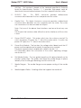
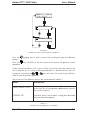
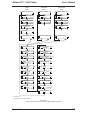
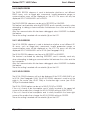
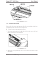
1.4 REAR PANEL COMPONENTS
In order to get acquainted with your Gerber P2C 1600 cutter, read the
following descriptions of the rear panel components. Figure 1-1 shows the
location of the main components.
6
3
8
1
2
4
5
7
3
1
2
4
5
FIGURE 1-1:
GERBER P2C 1600, REAR VIEW*
FOR PRACTICAL REASONS, ILLUSTRATIONS RELATE TO A SMALLER CUTTER MODEL. THE P2C 1600
CUTTERS DIFFER ONLY IN WIDTH AND NUMBER OF PINCH ROLLERS.
General Information
1-10
Gerber P2C™ 1600 Cutters
User’s Manual
1.
USB Port: - This interface is based on the standards specified in Universal
Serial Bus Specifications Revision 1.1. It provides high-speed serial bidirectional communication between the host computer and the cutter.
2.
RS-232-C Port: - This DB-9P connector provides bidirectional
communication between the host computer and the cutter.
3.
Parallel Port: - This 36-pin Centronics connector provides unidirectional
communication between the host computer and the cutter. The cutter
can receive but not transmit data via this port.
Note: Only one of the above three interfaces can be active at any one
time.
The first port that receives data will be the active interface until the cutter
is reset.
4.
Power ON/OFF switch: - This rocker switch turns the cutter on and off. To
switch the power ON, press the “I” side of the rocker switch. To switch the
power OFF, press the “O” side of the rocker switch.
5.
Power Entry Module: - The fuse box, the voltage select board, and the AC
power cord receptacle are located in the power entry module.
The power-up procedure is explained in detail in Section 1.6.
For information about the conversion of the cutter's operating voltage,
see Section 3.2.
6.
Roll Media Guides: - The two guides keep the roll in place laterally as the
media is pulled free. The guides also keep the media flanges in place
laterally when the flanges are being used to hold the roll.
7.
Media Flanges: - The media flanges ensure proper routing of the media
roll.
8.
Media Support Rollers: - Rotating rollers that support the media roll.
General Information
1-11
Gerber P2C™ 1600 Cutters
User’s Manual
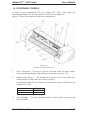
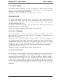
1.5 FRONT PANEL CONTROLS
In order to get acquainted with your Gerber P2C 1600 cutter, read the
following descriptions of the front panel controls and components.
Figure 1-2 shows the location of the main components.
FIGURE 1-2:
GERBER P2C 1600, FRONT VIEW
1.
Pinch roller lever: - This lever is used to raise and lower the pinch rollers
during media loading (media loading is discussed in Section 1.8).
2.
Media Drive Sleeves: - The media drive sleeves move the media only
when the pinch rollers are in the “down” position.
The following table lists the number of media drive sleeves installed on the
Gerber P2C cutter.
Number of sleeves
Short sleeve
Long sleeve
3.
D1600 SL
9
1
Tool Carriage: - The tool carriage holds the knife holder, the pouncing
tool or the pen.
General Information
1-12
Gerber P2C™ 1600 Cutters
User’s Manual
4.
Control Panel : - The control panel includes 12 keys which can be used to
control cutter activity, including remote mode for computer control, local
mode for manual operation, and menu mode. Each control panel
function is explained in Section 2.1.
5.
Display: - The 2x16 character display informs the user of the current status
of the cutting process or actions that need to be taken.
6.
Sensors: - The sensors detect the absence of media to prevent the knife
from damaging the cutting strip. When the cutter is turned on, the sensors
cause the media to move all the way to the front edge of the platen.
7.
Pinch rollers: - The pinch rollers (one at each side) exert downward force
through the media and onto the media sleeves. This squeezing between
the pinch rollers and media sleeves is what allows the cutter to
accurately advance and retract the media.
The D1600 Pro SL is equipped with two low pressure rollers in the middle to
keep vinyl media flat.
8.
Cutting strip: - This reddish-brown strip prevents damage to the knife tip
when the cutter is running and no media has been loaded. Because
cutting is done on the cutting strip, it is essential that it remain intact.
9.
Manual slitting knife: - When the cutter is done cutting a graphic, move
key. Use the manual slitting knife to
the media forward by pressing the
cut the finished graphic free from the media roll. Leave the loaded
media in place, ready for the next cut job.
10.
Stand: - A stand comes standard with the Gerber P2C 1600 cutter.
General Information
1-13
Gerber P2C™ 1600 Cutters
User’s Manual
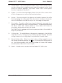
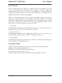
1.6 POWERING UP THE CUTTER
1.6.1 EARTHING (“GROUNDING”)
!
SAFETY WARNING
An insulated earth conductor must be installed as part of the branch
circuit that supplies power to the wall outlet to which the cutter is
connected. The earth conductor must have the same size, insulation
material, and thickness as the earthed and unearthed branch-circuit
supply conductors, but the insulating sheath should be green, or
green with yellow striping.
The earth conductor described above must be earthed at the
electrical distribution board, or, if power is supplied by a separate
system, at the power supply transformer/motor generator set.
The wall sockets into which the cutter is plugged must be of the
earthed type. The earth conductors serving said wall sockets must be
properly connected to earth.
CAUTION
Before plugging in the cutter's power cord to a power source, make
sure the cutter is set to the correct operating voltage (100 V, 120 V,
220 V, or 240 V AC).
(see section 3.2)
See Table 1-8 for the minimum and maximum operating voltages for the
different voltage ratings.
To check the operating voltage setting, locate the power entry module (shown
in Figure 1-1) on the cutter's rear panel. The power entry module shows four
possible voltage settings (100 V, 120 V, 220 V and 240 V). A pin next to one of
the voltage settings indicates the voltage setting currently selected for the
cutter. If this setting does not match the voltage supplied to your site, you will
have to change the voltage setting prior to powering up the cutter.
For information about the conversion of the cutter's operating voltage and the
exact fuse ratings, see Section 3.2.
General Information
1-14
Gerber P2C™ 1600 Cutters
User’s Manual
USA :
EUROPE:
THREE-PIN
OUTLET
MAKE SURE THIS IS
CONNECTED TO A
KNOWN EARTH
MAKE SURE THIS
IS CONNECTED TO A
KNOWN EARTH
THREE-PIN
PLUG
FIGURE 1-3:
EARTH CONNECTION
!
IMPORTANT OPERATIONAL TIP
Your cutter must only be used with a power outlet that is properly
grounded to earth. Use of an unearthed outlet exposes the operator to
the risk of electric shock and will also lead to malfunctioning of the
cutter.
1.6.2. POWER UP PROCEDURE
!
To power up the cutter, proceed as follows:
1.
Be sure the cutter is securely attached to its stand.
2.
Plug one end of the AC power cord into the AC power cord receptacle
on the cutter's rear panel.
3.
Plug the other end of the AC power cord into the wall socket.
4.
Press the "I" side of the ON/OFF rocker switch on the rear panel to switch
the cutter ON.
5.
The message "INSERT MEDIA" is displayed on the LCD if no media is loaded
and the pinch rollers are in the up position.
General Information
1-15
Gerber P2C™ 1600 Cutters
User’s Manual
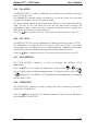
1.7 INSTALLATION OF A KNIFE, PEN OR POUNCING TOOL
1.7.1 KNIFE INSTALLATION
!
SAFETY WARNING
Your cutter uses razor-sharp knives. The knife blades may cause
serious personal injuries if handled without proper care. Use extreme
care when operating the cutter and when installing, removing or
handling the knife!
!
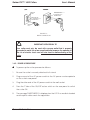
To set up your cutter for knife operation, proceed as follows:
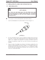
1.
Insert the knife blade into the knife holder as shown in Figure 1-4.
adjustment
knob
FIGURE 1-4
BLADE INSERTION
2.
Set the knife blade length to zero by aligning the blade tip with the tip of
the holder. An easy way of performing this is by holding the knife holder
against your fingertip and gradually increasing the blade length by
turning the adjustment knob until you feel the knife tip touching your
fingertip.
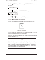
3.
Extend the tip of the blade according to the distance required for the
desired cutting media (t), as shown in Figure 1-5. The blade should only
extend beyond the knife holder sufficiently far to cut completely through
the film layer while not piercing the backing, which would put the cutting
strip at risk of being damaged.
General Information
1-16
Gerber P2C™ 1600 Cutters
User’s Manual
FIGURE 1-5
BLADE LENGTH ADJUSTMENT
4.
Turn the cutting depth adjustment screw clockwise to increase the cutting
depth. Turning the screw counterclockwise will decrease the cutting
depth.
FIGURE 1-6
SETTING KNIFE DEPTH
5.
To install the knife into the tool carriage:
- Loosen the clamp screw (2) and place the knife holder in the clamp
(1). Be sure that the knife holder is completely seated in the clamp.
- Tighten the clamp screw.
6.
Set the knife pressure as follows:
General Information
1-17
Gerber P2C™ 1600 Cutters
User’s Manual
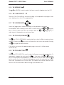
Press the
(MENU) key until the message “USER CONFIG 1” appears on
the display.
!!"#$%!&'()*+!,
Press the
jogging key until “KNIFE PRESSURE” is displayed.
!!-(*)$!.%$##"%$
!!,/01!!!!,23$#3
Press the
or
Press the
key to apply the new setting.
key to modify the knife pressure.
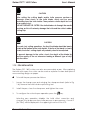
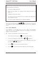
Press the 1 key to perform a knife depth test as illustrated in figure 1-7.
FIGURE 1-7
KNIFE DEPTH TEST PATTERN
The knife depth is set correctly when the test pattern is visible on the front
side of the media backing but not on the back.
In general, you should increase the knife depth and knife pressure when
using thicker types of vinyl.
NOTE
As the ideal knife pressure and depth settings depend on the
thickness and type of media to be cut, adjusting the pressure and
depth of the knife will require some practice. In general, the pressure
should be increased when cutting thicker types of vinyl. Thinner vinyl
usually requires lower knife pressure settings.
General Information
1-18
Gerber P2C™ 1600 Cutters
User’s Manual
CAUTION
After setting the cutting depth and/or knife pressure, perform a
thorough visual check of the knife blade, which can be seen
protruding from the knife holder. Then perform a knife depth test cut
on a scrap of vinyl.
DO NOT OPERATE THE CUTTER if the knife blade cuts through the media
backing, as this will seriously damage the knife and the cutter's rubber
cutting strip.
CAUTION
For most vinyl cutting operations, the tip of the blade should be barely
visible at the bottom of the knife holder. If the tip of the blade is clearly
visible, the knife’s cutting depth will probably need to be adjusted.
To prevent damage to the cutter, check the depth of the blade tip
and the quality of the cut whenever loading a different type of vinyl
into the cutter.
1.7.2 PEN INSTALLATION
The Gerber P2C 1600 cutters can also accommodate a pen. After replacing
the knife with a pen, the cutter can be used as a plotter to draw draft plots of
new or existing designs on paper.
!
To install the pen, proceed as follows:
1.
Loosen the clamp screw and swinging the clamp arm back (refer to Fig
1-6). Remove the knife holder or pouncing tool.
2.
Install the pen, close the clamp arm, and tighten the screw.
3.
To configure the cutter for pen operation, press the
key.
Selecting pen operation disables the knife offset correction and
changes the tip pressure from knife pressure to pen pressure. A small P
(for "Pen") will be displayed in the upper right corner of the LCD.
General Information
1-19
Gerber P2C™ 1600 Cutters
User’s Manual
1.7.3 INSTALLATION OF THE POUNCING TOOL
The Gerber P2C 1600 cutters can also be operated as pouncers by replacing
the knife with a pouncing tool.
!
To install the pouncing tool, proceed as follows:
1.
Loosen the clamp screw and swing the clamp arm back. Remove the
knife holder or pen (refer to Fig 1-6).
2.
Install the pouncing tool, close the clamp arm, and tighten the screw.
3.
To configure the machine for pouncing operation, press the
key.
Selecting pouncing operation disables the knife offset correction and
changes the tip pressure from knife pressure to pouncing pressure.
General Information
1-20
Gerber P2C™ 1600 Cutters
User’s Manual
1.8 LOADING MEDIA
The following procedures apply primarily when roll media is being used. When
using a long sheet, roll the sheet up so that it resembles a media roll. The rolled
sheet can then be aligned in the cutter in the same way as a media roll. When
using short sheets, alignment is not as important. If the sheet is cut off
perpendicularly, it can be aligned to the front border.
1.8.1 POSITIONING THE PINCH ROLLERS
The pinch rollers exert downward force on the drive sleeves. This pressure
creates traction that allows the cut sheet or roll media to be moved along the
X-axis (forward/backward).
Proper movement of the media will only occur if the pinch rollers are correctly
positioned over the drive sleeves.
The pinch rollers are raised and lowered simultaneously by means of the pinch
roller lever located on the right side of the cutter next to the control panel. The
rollers must be raised before media can be loaded into the cutter.
When raised, the pinch rollers can be moved manually left and right along the
pinch roller shaft. This way, they can be easily positioned in a detent (click
position). The cutter should not be used unless all needed pinch rollers are
secured in a detent to ensure optimum media traction.
When the pinch rollers are raised, the message "LOWER CAM ROLLERS" is
displayed on the LCD.
CAUTION
Always make sure that the pinch rollers are in the fully raised position
before sliding them left or right.
The pinch rollers MUST be positioned correctly and lowered onto the media
before an automatic load sequence will be initiated. Make sure that the pinch
rollers are positioned directly above the drive sleeves. The left pinch roller
should be positioned in a detent (click position). The right pinch roller should be
positioned somewhere along the wide drive sleeve, which has detents only at
its extreme right and left ends. The drive drum will move the media only when
the pinch rollers are lowered onto the sleeves.
General Information
1-21
Gerber P2C™ 1600 Cutters
User’s Manual
Before lowering the pinch rollers, carefully check the position of the rollers in
relation to the drive sleeves. When the pinch rollers are DOWN, they must run
over the sleeves in order to ensure proper media traction. It is very important
that the left and right edges of the media always rest on sleeves. Position the
pinch rollers so that they are 3 to 15 mm (0.1" to 0.6") in from the edge of the
media.
On the Gerber P2C 1600 cutter, two, three or more sleeves may be partly or
fully covered, depending on the media width used. To ensure correct
positioning of the pinch rollers, reference marks in the shape of inverted
triangles have been provided on the head guide.
The center low-pressure roller is used to enhance media routing and keep the
vinyl flat. Ideally, this roller should be positioned halfway between the two
edge rollers but always over one of the drive sleeves.
The center low-pressure roller(s) can be in the raised position on the Gerber
P2C D1600 cutters when media narrower than 600 mm is being cut.
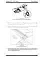
1.8.2 FEEDING AND POSITIONING MEDIA
The following load procedure has been found to be very reliable. Adhere to
these step-by-step instructions when loading media.
! To load media, proceed as follows:
1.
Raise the pinch rollers by lowering the pinch roller lever located at the
back of the cutter.
FIGURE 1-8:
MEDIA POSITIONING
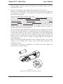
2.
When working with roll media, proceed by inserting a media flange at
each end of the roll and then tighten the thumbscrews until the media roll
is firmly gripped between the flanges. Make sure the flanges are firmly
General Information
1-22
Gerber P2C™ 1600 Cutters
User’s Manual
pressed against the roll. Place the flanges on the media support rollers at
the rear of the cutter.
3.
Position the flanges on the support rollers at the rear of the cutter.
Slide the two media guides under the media roll so that each flange rests
in the groove in the guide. In this position, the media roll and guides can
be shifted left and right.
Feed the media from the rear of the cutter.
Position the left edge of the media on the leftmost drive sleeve and then
check to see whether the right edge of the media is positioned over the
wide drive sleeve. If it is, the left pinch roller can be positioned in the detent
above the leftmost sleeve. Then, the right pinch roller can be positioned
somewhere over the wide drive sleeve according to the media width. The
right pinch roller can be located anywhere between the two outer detent
positions above the long drive sleeve. This flexibility allows a variety of
media widths to be accommodated.
Should the above procedure fail to work because the media is too narrow
to reach the long drive sleeve, try positioning the left media edge over the
second drive sleeve in from the left. Then position the right media edge
somewhere on the wide drive sleeve. Repeat this process if the media is still
found to be too narrow by locating the left media edge over the third
drive sleeve in from the left. Adjust the right edge of the media as
described above.
Follow the same general procedure when loading media on the wider
models of the Gerber P2C cutters, which have been provided with
additional sleeves.
If necessary, continue to reposition the media until both edges are
positioned over a drive sleeve.
FIGURE 1-9:
FEEDING ROLL MEDIA USING MEDIA FLANGES
General Information
1-23
Gerber P2C™ 1600 Cutters
User’s Manual
FIGURE 1-10:
FEEDING ROLL MEDIA WITHOUT USING MEDIA FLANGES
4.
Make sure that the media follows a straight path from the roll to the cutting
area. This can be accomplished by sliding the media guides left and right
as needed along the media support rollers.
5.
The pinch rollers should be positioned over the drive sleeves and about 3 to
15 mm (0.1” to 0.6”) in from the edges of the media.
FIGURE 1-11
PINCH ROLLER POSITIONING
6.
Raise the pinch roller lever to lower the rollers onto the media and drive
sleeves. The tool carriage will automatically begin moving left and right to
sense the usable media width.
General Information
1-24
Gerber P2C™ 1600 Cutters
User’s Manual
NOTE
It is not necessary to pull the media manually from the roll. The cutter
will unroll the media automatically during the load sequence.
7.
The positioning and routing of sheet material is identical to that of roll
media.
8.
The cutter is now ready for the actual load procedure, which may be
controlled from the control panel.
General Information
1-25
Gerber P2C™ 1600 Cutters
User’s Manual
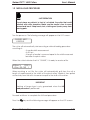
1.9 MEDIA LOAD PROCEDURE
SAFE OPERATION
Do not place any objects in front of, or behind, the cutter that could
interfere with cutter operation. Make sure the media is free to move
forward and back. Keep hands, hair, clothing and jewelry away from
moving parts.
Turn the power on. The following message will appear on the LCD screen:
!!.4$5#$!65*3
!!!4'57*(+!!!
The cutter will automatically start executing a minimal loading procedure
consisting of:
- A media width measurement
- A 45° test
- A length of media is unwound equal to the width measured
between the pinch rollers
When the cutter indicates that it is “ONLINE”, it is ready to receive a file:
80099:;!!!,/01!!<=99!'(4*($>,
When receiving a cut file, the cutter will automatically pull from the roll a
length of media equal to the width of the pinch rollers. Media is then pulled
successively from the roll in increments equal to the width of the rollers.
IMPORTANT
Tracking of longer signs is only guaranteed when the full
load procedure is performed!
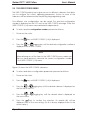
Proceed as follows to complete the full load procedure:
Press the
key and the following message will appear on the LCD screen:
General Information
1-26
Gerber P2C™ 1600 Cutters
Press the
screen:
User’s Manual
key again and the following message will appear on the LCD
Press the 1 key to load media from a roll. Press the 2 key to load media in sheet
form.
If “sheet” is selected and the sensors are enabled, then the sheet is
automatically loaded.
If “roll” is selected, the following display will appear on the LCD:
Using the
,
,
, and
jogging keys, the knife (i.e., the origin) can be
repositioned to any location. Press the
origin.
key to confirm the selected point of
The media length needed for a task can be entered by pressing the
and
jogging keys.
The XXXX-value is the media length as defined with the
and
jogging
keys.
The YYYY-value is the cuttable width of the media as measured by the cutter.
Note: when the media length displayed is zero (0), the default media length
will be used.
to confirm the length and the cutter will start “shuffling” the vinyl in
Press
order to establish a track on the vinyl.
80099:;!!!,/01!!<=99!!'(4*($!,
The cutter is now ready to receive a file.
General Information
1-27
Gerber P2C™ 1600 Cutters
User’s Manual
80099:;!!!,/01!!<=99!!'(4*($!,
The cutter has been selected by the computer.
However, if you pressed
, the default media length is displayed:
An XXXX-value appears. (2000mm is the default value.) The default values can
be changed by pressing the
jogging keys.
(+10),
(-10),
(-100), and
(+100)
to confirm the length, and the cutter will start shuffling the vinyl in
Press
order to set a track on the vinyl.
80099:;!!!,/01!!<=99!!'(4*($!,
The cutter is now ready to receive a file.
80099:;!!!,/01!!<=99!!'(4*($!,
The cutter has been selected by the computer.
When the built-in media sensors detect the end of the roll, the message
END OF MEDIA will be displayed. The display will show the actual length of
the loaded media.
If that length is sufficient, press 1 to ACCEPT.
If not, press 2 to ABORT and the media will automatically return to its
origin.
CAUTION
When you accept the loaded area in sheet mode, the cutter will clip the
sign to be cut in case of insufficient media. Compare the loaded media
with the area needed for the sign!
General Information
1-28
Gerber P2C™ 1600 Cutters
User’s Manual
SECTION 2
2 OPERATION
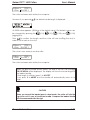
2.1 THE CONTROL PANEL
Figure 2-1 shows the control panel of the Gerber P2C 1600 cutters. The main
functions of the liquid crystal display (LCD) and the control panel keys are
explained in the following paragraphs.
FIGURE 2-1:
CONTROL PANEL, GERBER P2C 1600
Operation
2-1
Gerber P2C™ 1600 Cutters
User’s Manual
2.1.1 THE LIQUID CRYSTAL DISPLAY
The 32-character liquid crystal display (LCD) consists of two lines of 16
characters each. The LCD provides cutter status information during operations
and displays menu options for the configuration of the cutter.
The contrast of the LCD can be adjusted from the control panel in order to
ensure optimum readability under varying lighting conditions.
Instructions for adjusting the LCD contrast are given in Section 2.6.11.
The various menu and submenu items are always presented in a loop. When
the last item in the menu is displayed, pressing the appropriate key will
automatically take you back to the first item in the same menu or submenu.
Next to the status messages and/or menu options displayed on the LCD, arrow
,
,
, and
jogging keys and the
symbols representing the
key will tell you what keys to press to go to the next menu item (top line of the
display) or to the next value for a given submenu item (bottom line of the
display).
2.1.2 THE RESET/LOAD KEY
The
key (RESET/LOAD) is used to move the origin, initiate a load sequence,
reset the cutter, abort the cut in progress or recut the last file. When the
key (RESET/LOAD) is pressed, the cutter goes offline, suspends all operations in
key until SET
progress, and displays the RESET/LOAD menu. Press the
ORIGIN, LOAD, RESET, ABORT, SPECIAL LOAD or RECUT is displayed. To confirm
key (ENTER). To execute the SET ORIGIN
RESET, ABORT or RECUT, press the
,
,
, and
jogging
instruction, move the knife origin using the
keys and then press the
key (ENTER) to confirm the new origin position.
Press the 1 or 2 key to initiate a load sequence for a ROLL or SHEET, respectively.
key (ENTER) to initiate the SPECIAL LOAD instruction. Then position
Press the
the knife tip directly over the origin-marker using the jogging keys. The cutter
will return to ONLINE status should any of these instructions be terminated.
The SET ORIGIN instruction is used to move the knife origin.
The LOAD instruction is used to initiate a load sequence.
The RESET instruction performs a complete reset of the cutter.
The ABORT instruction simply cancels the cut in progress. Aborting a cut will not
reset the cutter parameters; the parameters that had been selected for the cut
remain in effect.
Operation
2-2
Gerber P2C™ 1600 Cutters
User’s Manual
The SPECIAL LOAD instruction is used to initiate registration of the OPOS markers
just before a contour cut is begun. See the section on OPOS for more
information about contour cutting.
The RECUT instruction recuts the last file sent to the cutter (provided that it fit in
the buffer).
When using the multiple recut function, the different copies will be cut in a way
that minimizes media waste. The distance between the copies can be
changed (See Section 2.4.18).
2.1.3 THE ONLINE KEY
The
key (ONLINE) toggles the cutter between online and offline operation.
key is pressed, the selected mode (ONLINE or OFFLINE) is
When the
displayed on the LCD.
key while
Selecting OFFLINE suspends all operations in progress. Pressing the
the cutter is offline will return the cutter to online status and the suspended
operation will resume.
While the cutter is offline, the following operations can be performed:
•
Press the
right.
•
Press the
or
jogging key to scroll the media forward (towards you)
or backward (away from you). Scrolling the media is useful when it comes
time to manually cut the graphic from the rest of the media.
•
Press the
key (TOOL UP/DOWN) to raise or lower the active tool. The
tool is raised automatically if it is not moved for approximately eight
seconds.
or
jogging key to move the tool carriage to the left or
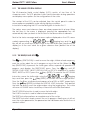
2.1.4 THE MENU KEY
key (MENU) is used to select a menu. Pressing the
key will cause the
The
cutter to go offline and suspend all operations in progress. Pressing the
key
repeatedly will display the different menus one at a time. As the menu options
key when the last option is displayed will
are on a loop, pressing the
automatically return you to the first option.
The different menus are illustrated in Figure 2-2.
Operation
2-3
Gerber P2C™ 1600 Cutters
User’s Manual
80099:;!!!,/01!!<=99!'(4*($>,
Menu
!!"#$%!&'()*+!,
Menu
!!*(3$%(54!3$#3#
Menu
FIGURE 2-2:
GERBER P2C 1600 CONFIGURATION SUBMENUS
Press the
options.
jogging key to select a menu by scrolling through the different
Press the
operation.
key (ONLINE) to exit the menus and resume the previous online
Under normal conditions, the cutter is online; it may then be selected by the
host computer for a cutting or plotting operation or deselected by the host
,
or
computer. Pressing the
order to initiate another operation.
key will cause the cutter to go offline in
The contents of the different menus are summarized in Table 2-1.
MENU
DESCRIPTION
USER CONFIG 1 (->4)
Selects a given active cutter configuration from one
of the four sets of configuration parameters stored in
the cutter's memory
INTERNAL TEST
Activates one of the resident cutting plots provided
for informational purposes.
TABLE 2-1:
CONTENTS OF THE GERBER P2C 1600 MENUS
Operation
2-4
Gerber P2C™ 1600 Cutters
User’s Manual
2.1.5 THE ENTER KEY
The
key (ENTER) is used to select the item currently displayed on the LCD.
2.1.6 THE 1 AND 2 KEYS 1
-2
The use of the 1 and 2 keys varies according to the operation in progress; their
use is displayed on the LCD as appropriate.
2.1.7 THE JOGGING KEYS
Use of the jogging keys varies according to the operation in progress.
For example, when working in the USER CONFIG menu, the
key is used to select the new user number and the
used to go to the previous or next menu item.
or
or
jogging
jogging key is
2.1.8 THE TOOL UP/DOWN KEY
key (TOOL UP/DOWN) is used while the cutter is offline to raise or lower
The
the tool. Pressing the
key once will lower the tool onto the media. Pressing
the
key again will raise the tool.
If the tool is not moved for approximately eight seconds, it will be raised
automatically.
2.1.9 THE TOOL SELECT KEY
The
key (TOOL SELECT) is used to select knife, pen or pouncing operation. To
temporarily change the tool, press the
key, then press the
or
jogging
key until the desired tool appears on the second line of the LCD. Press the
key to confirm the tool. An asterisk (!) appears next to the selected tool. When
the cutter is powered on the next time, the default tool will be selected. See
Section 2.4.4 for information about setting up the default tool.
Operation
2-5
Gerber P2C™ 1600 Cutters
User’s Manual
2.2 NORMAL OPERATION
The term "normal operation" covers online operation, offline operation, and
local operation, i.e. the three types of operation for actual cutting or plotting.
They are explained in further detail in the following paragraphs.
2.2.1 ONLINE AND OFFLINE
Online and offline are two important concepts when using the Gerber P2C
1600 cutters. The cutter is online only when the following message is displayed
on the LCD:
80099:;!!!,/01!!<=99!'(4*($>,
This display message should be read as follows:
800 mm/s
120 g
K
.45 mm
ONLINE
1
=
=
=
=
=
=
velocity
knife pressure, pen pressure or pouncing pressure
knife operation (K), pen operation (P)
knife offset
cutter is ready to receive data
current user configuration
In all other cases, the cutter is offline.
When online, the cutter can be addressed by the host computer, which means
that the cutter will execute cutting or plotting instructions issued by the host
computer's application software. The host computer will first issue a SELECT
sequence to the online cutter, and the message "?'(4*($" will be displayed
on the LCD. The asterisk indicates that the host is in communication with the
cutter: i.e., the cutter is now “selected” by the computer.
When the cutter is online and ready to receive instructions from the host
computer, it will remain deselected until actual instructions from the computer
are received. When the cutter is online, but has not been selected by the host
computer, the message "'(4*($" is displayed on the LCD, without the asterisk.
For normal cutting operations, the cutter MUST be online, so that it can receive
instructions from the host computer and the cutting/plotting software.
Operation
2-6
Gerber P2C™ 1600 Cutters
User’s Manual
When the cutter is online, but has not been selected by the host computer, the
following conditions must be met:
•
The cutter must be powered ON.
•
Media must be loaded. For detailed media loading instructions, see
Section 1.8.
•
The proper tool must be installed.
•
The cutter must be connected to the host computer via a USB, RS-232-C
link or a parallel interface.
•
The cutter must be configured for the scheduled operation.
,
or
key. Pressing any of these keys
To put the cutter offline, press the
will suspend the current cutting/plotting operation until the cutter is again put
online.
2.2.2 LOCAL OPERATION
Local operation is only possible while the cutter is offline. Local operation
means that the cutter is operated directly by the operator via instructions
entered on the control panel.
!
To work in local operation mode, proceed as follows:
1.
If the cutter is still online, press the
2.
To move the carriage left or right, press the
3.
To scroll the media forwards (towards you) or backwards (away from
or
jogging key.
you), press the
4.
Press the
key to move the tool head up or down.
5.
Press the
key to end local mode and put the cutter online again.
Operation
key once to select offline.
or
jogging key.
2-7
Gerber P2C™ 1600 Cutters
User’s Manual
2.3 THE USER CONFIG MENU
The USER CONFIG(uration) menu gives access to different submenus that allow
you to configure the cutter's operating parameters. Access to some of the
submenus will be determined by the plotting language being used.
Four different user configurations can be saved. The selected configuration
number is displayed on the LCD next to the USER CONFIG message. These four
USER CONFIG 1(->4) menus are maintained independently.
!
To select another configuration number, proceed as follows:
1.
Power on the cutter.
2.
Press the
3.
or
jogging key until the desired configuration number is
Press the
displayed next to USER CONFIG.
key until USER CONFIG 1(->4) is displayed.
NOTE
Before altering any of the items in the USER CONFIG menu, make sure
that you have previously selected the correct configuration number
in the USER CONFIG 1(->4) menu.
Figure 2-3 shows the USER CONFIG submenus.
!
To select and alter a configuration parameter, proceed as follows:
1.
Power on the cutter.
2.
Press the
3.
or
jogging key until the desired submenu is displayed on
Press the
the first line of the LCD.
4.
or
Press the
the second line.
5.
key to confirm the selection. An asterisk (!) will be
Press the
displayed next to the new setting. (An ! is always displayed next to the
active value.)
Operation
key until USER CONFIG 1(->4) is displayed.
jogging key until the desired value is displayed on
2-8
Gerber P2C™ 1600 Cutters
DRAG
KNIFE
User’s Manual
BALLPOINT
OR PEN
POUNCING
TOOL
!!"#$%!&'()*+!,
!!"#$%!&'()*+!,
!!"#$%!&'()*+!,
!!-(*)$!.%$##"%$
!!,/01!!!!,23$#3
!!@$4'&*3A
!!!!!80099:;!!!
!!@$4'&*3A
!!!!!80099:;!!!
!!-(*)$!'))#$3
!!!<=99!!!,23$#3
!!.$(!.%$##"%$
!!801!!!!!,23$#3
!.'"(&$!.%$##"%$
!!!<=99!!!,23$#3
!!@$4'&*3A
!!!!!80099:;!!!
!!.'"(&$!+5.
!!!!!!,99!!
!!'@$%&"3
!!!!!!!,
!!#A#3$B!#$3".
!!#A#3$B!#$3".
!!&'(&53*(53*'(
!!!!!!!0
!!7B:.4!$%%'%#
!!!!!*+('%$7
*
!!#B''3C*(+
!!!!!!'))
!!C.:+4!$%%'%#
!!!!!*+('%$7
**
!!$B"453$
!!!!!7B:.4
!!C.:+4!'%*+*(
!!!%*+C3!)%'(3
**
!!3''4
!!!7%5+!-(*)$
!!B$7*5!#$(#'%
!!!!!!!'(
*
*
!!B$("!"(*3#
!!!!!B$3%*&
*
!!5"3'4'57
!!!!!!!'(
!!577%$##*(+
!!!!!!0/=99
*
!!#.$&*54!4'57
!!!!!!'.'#
!!D5"7!%53$
!!!!!!EF00
!!3''4!&'BB5(7
!!!!!5&&$.3
!!.5%*3A
!!!!!!('($
!!4'57!'(!6!&B7
!!!!!!!'(
!!%3#:73%
!!!!!3'++4$
!!)4$G!&"3
!!'))!!!!!,23$#3
!!#A#3$B!#$3".
*
!!%$&"3!'))#$3
!!!!!!!=99
* in DM/PL only
** IN HP-GL AND HP-GL/2 ONLY
FIGURE 2-3:
FLOWCHART SHOWING FACTORY PRESET MENU SETTINGS
Operation
2-9
Gerber P2C™ 1600 Cutters
User’s Manual
2.3.1 KNIFE PRESSURE
The KNIFE PRESSURE submenu is used to set or modify the cutting pressure of the
knife.
The default knife pressure value is 120 grams.
The knife pressure can be set between 0 and 400 grams.
The knife pressure value is set in 5-gram increments.
The active knife pressure value is marked with an asterisk (!) on the LCD.
Knife pressure setup is explained in detail in section 1.7.1.
2.3.2 KNIFE OFFSET
The KNIFE OFFSET submenu is used to set or modify the distance between the tip
of the knife and the axis.
The default knife offset value is .45 mm.
The value can be set between 0 and 1 mm.
Make sure that the selected knife offset value is appropriate for the knife being
used.
Some fine-tuning may be necessary because of the knife’s mechanical
tolerances. To verify the knife offset, a test can be cut by pressing the 1 key.
If the offset value is set too low, the rectangles will not close.
If the offset value is set too high, the rectangles will be distorted.
The offset test is illustrated below.
2.3.3 POUNCING PRESSURE
The POUNCING PRESSURE submenu is used to set or modify the amount of
pressure exerted upon the pouncing tool.
The default pouncing pressure value is 120 grams.
The pouncing pressure can be set between 0 and 400 grams.
The pouncing pressure value is set in 5-gram increments.
The active pouncing pressure value is marked with an asterisk (!) on the LCD.
Pouncing pressure setup is explained in detail in section 1.7.3.
2.3.4 VELOCITY
The VELOCITY submenu is used to set or modify the velocity of the tool.
The default velocity is 800 mm/s (20 ips).
The velocity can be set between 50 mm/s (2 ips) and 1000 mm/s (40 ips).
Operation
2-10
Gerber P2C™ 1600 Cutters
User’s Manual
2.3.5 OVERCUT
The OVERCUT submenu enables you to establish an overcut to facilitate
weeding.
The default overcut value is 1.
The overcut setting can be disabled (=0) or set to any value between 0(=off)
and 10. One unit is about 0.1 mm or 0.004 ".
The current overcut value is marked with an asterisk (!) on the LCD.
2.3.6 POUNCING GAP
The pouncing gap submenu is used to set or modify the distance between the
pounced holes. Pouncing gap only applies when the machine is in pounce
mode.
The default pouncing gap is 1 mm.
The value can be set between 0 and 50 mm.
The current pouncing gap value is marked with an asterisk (!) on the LCD.
2.3.7 SYSTEM SETUP
The SYSTEM SETUP submenu includes menu items normally needed only during
initial setup when the cutter is made to communicate with the computer and
software.
key to access the different submenu items, which are explained
Press the
in section 2.4.
Operation
2-11
Gerber P2C™ 1600 Cutters
User’s Manual
2.4 SYSTEM SETUP
Refer to Figure 2-3.
2.4.1 CONCATENATION
The CONCATENATION feature increases the speed and cut quality when high
resolution data is being cut. However, when changing back to normal
characters, concatenation should be deactivated by setting the parameter to
0.
The active concatenation value is marked with an asterisk (!) on the LCD.
2.4.2 SMOOTHING
The SMOOTHING feature applies to graphics that have curves made up of
many short vectors. SMOOTHING smoothes the vectors to achieve a more
rounded appearance.
SMOOTHING is set to OFF by default.
2.4.3 EMULATE
The EMULATE submenu is used to select the cutter’s active cutting/plotting
language.
The Gerber P2C 1600 cutters support DM/PL, HP-GL and HP-GL/2.
The active plotting language is marked with an asterisk (!) on the LCD.
NOTE
The cutter’s active cutting/plotting language MUST match the active
cutting/plotting language set in the cutting software.
Always select a language that is supported by the host computer's
cutting software.
Whenever possible, select the DM/PL menu option which sets the active
cutting/plotting language to Houston Instrument Digital Microprocessor/Plotting
Language (DM/PL). This selection will allow the cutter to operate with DM/PLbased cutting/plotting software. This language, having special command
extensions for cutting, normally gives superior cutting performance.
Select the HP-GL menu option to set the active cutting/plotting language to
Hewlett-Packard Graphics Language. The cutter will emulate an HP model
758XB plotter (with selectable origin, see 2.4.12).
Operation
2-12
Gerber P2C™ 1600 Cutters
User’s Manual
2.4.4 TOOL
The TOOL submenu is used to select the default tool at power up.
Select PEN to configure the cutter for plotting operations.
Select DRAG KNIFE to configure the cutter for cutting operations.
Select POUNCING TOOL to configure the cutter for pouncing operations.
To temporarily select a tool other than the default tool, see section 2.1.9.
2.4.5 MENU UNITS
The MENU UNITS submenu allows English or metric menu units to be selected for
DM/PL operations. Menu units in HP-GL & HP-GL/2 are always in metric.
English units are the default setting for models sold in the US.
Metric units are the default setting for models sold in Europe.
The setting for the active menu units is marked with an asterisk (!) on the LCD.
2.4.6 ADDRESSING
The ADDRESSING submenu is used to select the cutter's default DM/PL useraddressable resolution.
The user-addressable resolution can be set to 0.025 mm or 0.1 mm when using
metric menu units, or 0.001” or 0.005" when using English menu units.
The default addressing resolution is 0.025 mm (metric), 0.001" (English).
In HP-GL & HP-GL/2, the addressing is fixed at 0.025 mm.
The active resolution value is marked with an asterisk (!) on the LCD.
2.4.7 BAUD RATE
The BAUD RATE submenu is used to set or modify the baud rate for RS-232-C
serial communication between the cutter and the host computer.
The baud rate can be set to any of the following values: 2400, 4800, 9600,
19200 or 38400 bps.
The default baud rate is 9600 bps.
The active baud rate value is marked with an asterisk (!) on the LCD.
NOTE
The cutter’s baud rate setting MUST match the host computer's baud
rate setting.
Operation
2-13
Gerber P2C™ 1600 Cutters
User’s Manual
2.4.8 PARITY
The PARITY submenu is used to set or modify the byte format and parity type for
RS-232-C serial communication between the cutter and the host computer.
The default parity setting is bit 8 = 0 (8 data bits, no parity, the 8th bit being a
low bit). The parity can be set to any of the following values:
LCD information
BIT 8 = 0
BIT 8 = 1
EVEN
ODD
Parity setting
8 data bits, no parity
8 data bits, no parity
7 data bits, 1 parity bit
7 data bits, 1 parity bit
Remarks
bit 8 = low (0)
bit 8 = high (1)
parity bit = even
parity bit = odd
The active parity setting is marked with an asterisk (!) on the LCD.
NOTE
The cutter’s parity setting MUST match the host computer's parity
setting.
2.4.9 RTS/DTR
The RTS/DTR submenu controls the Request To Send (RTS) and Data Terminal
Ready (DTR) signals for the cutter's RS-232-C serial communications interface for
hardware handshaking.
RTS/DTR can be set to TOGGLE (hardware handshaking) or HIGH (software
handshaking).
The RTS/DTR default value is TOGGLE.
The active handshake setting is marked with an asterisk (!) on the LCD.
Operation
2-14
Gerber P2C™ 1600 Cutters
User’s Manual
2.4.10 DM/PL ERRORS
The DM/PL ERRORS submenu is used to determine whether or not different
DM/PL errors, such as illegal plot commands, invalid parameter ranges or
communication errors will be displayed on the LCD. This menu will only be
displayed if PLOT LANGUAGE is set to DM/PL.
The DM/PL ERRORS submenu can be set to REPORTED or IGNORED.
This feature is activated by selecting REPORTED, and is normally used only when
attempting to debug a communication link between the cutter and the host
computer.
After the communication link has been debugged, select IGNORED to disable
the feature.
The active setting is marked with an asterisk (!) on the LCD.
2.4.11 HP-GL ERRORS
The HP-GL ERRORS submenu is used to determine whether or not different HPGL errors, such as illegal plot commands, invalid parameter ranges or
communication errors will be displayed on the LCD. This menu will only be
displayed if PLOT LANGUAGE is set to HP-GL (See Paragraph 2.4.3).
The HP-GL ERRORS submenu can be set to REPORTED or IGNORED.
The feature is activated by selecting REPORTED, and is normally used only
when attempting to debug a communication link between the cutter and the
host computer.
After the communication link has been debugged, select IGNORED to disable
the feature.
The active setting is marked with an asterisk (!) on the LCD.
2.4.12 HP-GL ORIGIN
The HP-GL ORIGIN submenu will only be displayed if the PLOT LANGUAGE is set
to HP-GL. (See Paragraph 2.4.4). The HP-GL ORIGIN submenu is used to set the
origin in the center (see HP-GL 758x) or the bottom-right corner (see HP-GL
7475) of the loaded media.
The HP-GL ORIGIN option can be set to RIGHT_FRONT or CENTER.
If the cut is found to be incomplete, and is wholly located in the upper left
corner of the media, then change the HP-GL ORIGIN setting to RIGHT FRONT.
If the cut is found to be incomplete, and is wholly located in the lower right
corner of the media, then change the HP-GL ORIGIN setting to CENTER.
The active setting is marked with an asterisk (!) on the LCD.
Operation
2-15
Gerber P2C™ 1600 Cutters
User’s Manual
2.4.13 MEDIA SENSOR
The MEDIA SENSOR submenu is used to activate or deactivate the media
sensors. The sensors detect the presence and absence of media to prevent
damage to the cutting strip and knife tip.
The active setting is marked with an asterisk (!) on the LCD.
2.4.14 AUTOLOAD
The AUTOLOAD option allows the user to control how vinyl is pulled from the
roll. When AUTOLOAD is ON, the cutter will automatically unroll the vinyl as
needed. When AUTOLOAD is OFF, the user should manually unroll sufficient
vinyl before beginning to cut.
The default AUTOLOAD setting is ON. The best results and performance are
guaranteed when using this setting.
The active setting is marked with an asterisk (!) on the LCD.
2.4.15 TOOL COMMAND
TOOL COMMAND is used to determine whether the DM/PL and HP-GL
pen/knife-select commands (the P and SP commands, respectively) are
ignored or accepted.
When the TOOL COMMAND option is set to “ACCEPT”, the P or SP commands
will change the selected tool in the cutter according to the suffix that follows
the pen/knife command. When a P2 command is sent, the cutter’s LCD will
prompt the user with the following message: “INSERT PEN”. When the TOOL
COMMAND option is set to “IGNORE”, the pen/knife commands are ignored.
The default setting is “ACCEPT”.
The active setting is marked with an asterisk (!) on the LCD.
2.4.16 LOAD ON W CMD
The LOAD ON W CMD submenu will only be displayed if the PLOT LANGUAGE is
set to DM/PL (See Paragraph 2.4.4). When receiving the DM/PL Windowcommand (W-command), LOAD ON W CMD determines whether media is
loaded apart from the scaling function. In addition to scaling, the W-command
is very useful when cutting long signs. Media loading will go more smoothly
with the W-command because sufficient media will be pulled from the roll at
once. Then, even when AUTOLOAD is off, there is no need to unroll the media
manually.
Operation
2-16
Gerber P2C™ 1600 Cutters
User’s Manual
2.4.17 FLEX-CUT
FLEX-CUT can be set to OFF, Mode 1 or Mode 2. When set to Modes 1 or 2, the
cutter will alternately cut one length with full pressure and one length with
reduced pressure. FLEX-CUT offers the advantage of cutting completely
through the material while, at the same time, allowing the material to stay
together by means of small media bridges.
MODE 1 is the quickest mode, but is less precise because the pressure changes
during the cutting. MODE 2 is considerably slower than Mode 1, but at the
same time it offers greater precision because the cutter stops at every change
of pressure. Pressing the 1 key will activate the configuration menu, which
allows you to set the cutting pressure and cut length.
1. CUT LENGTH
This parameter determines the length that will be cut with full pressure. By
pressing the 1 key, the FLEX-CUT test pattern will be cut.
2. FLEX-CUT LENGTH
This parameter determines the length that will be cut with reduced or no
pressure. By pressing the 1 key, the FLEX-CUT pattern will be cut.
3. FLEX PRESSURE
This parameter determines the pressure of the FLEX-CUT LENGTH. By pressing the
1 key, the FLEX-CUT test pattern is cut.
2.4.18 RECUT OFFSET
The RECUT OFFSET submenu is used to set or modify the distance between
graphics when making multiple recuts.
The distance can be set between 0 and 255 mm.
The default recut offset value is 0 mm.
The active recut offset value is marked with an asterisk (!) on the LCD.
Operation
2-17
Gerber P2C™ 1600 Cutters
User’s Manual
2.5 INTERNAL TESTS MENU
!
To access an internal cut, proceed as follows:
1.
Power on the cutter.
2.
Load cutting or plotting media.
3.
Install a knife or pen.
4.
Press the
key.
5.
Press the
6.
To perform the plot, press the
key until INTERNAL TESTS is displayed. Press the
or
jogging
jogging key until the desired internal plot is displayed.
key.
To exit this menu and go to another menu, press the
menu is displayed.
key until the desired
key to exit all menus and return the cutter to online status.
Press the
!!*(3$%(54!3$#3#
!!
!!*(3$%(54!3$#3#
!!&"3!D'%7$%
!!*(3$%(54!3$#3#
!!45(+"5+$
!!*(3$%(54!3$#3#
!!B$("!.4'3
!!*(3$%(54!3$#3#
!!%'B!%$@*#*'(
!!*(3$%(54!3$#3#
!!%5B!3$#3
!!*(3$%(54!3$#3#
!!&'()*7$(&$
!!*(3$%(54!3$#3#
!!#$%@*&$!.4'3
!!*(3$%(54!3$#3#
!!*(#3544!B$("
!!*(3$%(54!3$#3#
!!7*(!&"3
!!*(3$%(54!3$#3#
!!'.3*&54!#$(#'%
!!*(3$%(54!3$#3#
!!&'*4!#$3".
!!*(3$%(54!3$#3#
!!&54!B$7*5
!!*(3$%(54!3$#3#
!!#$(#'%!#$3".
!!*(3$%(54!3$#3#
!!4&7!&'(3%5#3
!!*(3$%(54!3$#3#
!!&54!'.'#
!!*(3$%(54!3$#3#
!!&54*D%53$!G:A
!!*(3$%(54!3$#3#
!!'.'#!#$33*(+#
!!*(3$%(54!3$#3#
!!%#H/I/!.4'3
!!*(3$%(54!3$#3#
!!#A#3$B!3$#3#
FIGURE 2-4:
INTERNAL TESTS SUBMENUS
Operation
2-18
Gerber P2C™ 1600 Cutters
User’s Manual
2.5.1 CUT BORDER
CUT BORDER is used to cut the border of the media area as defined during the
load sequence. This function can be used to verify the exact cutting area.
2.5.2 MENU PLOT
MENU PLOT produces a hard copy of the present cutter configuration, i.e. the
parameter settings in the USER CONFIG submenus described in Section 2.3. The
plot is organised by menu categories to show the current values for the various
USER CONFIG 1(->4) configurations. To run this plot, load a sheet of plotting
paper and install a pen.
NOTE
It is strongly recommended that a MENU PLOT be plotted each time
the cutter configuration is altered. The resulting plot should be kept
with the cutter documentation in order to provide other users with
details about the unit’s actual configurations.
2.5.3 CONFIDENCE CUT
The CONFIDENCE cut performs an electrical and mechanical test of the cutter
to make sure that the cutter is fully operational. A sheet of media at least
A3/A- size should be used for this plot.
2.5.4 DIN CUT
The DIN CUT performs an electrical and mechanical test of the cutter to check
cut quality. It also provides the user with feedback on knife setting, knife
pressure, knife offset, and cutting depth.
This cut is always run as a DIN A4 portrait/A-size image, regardless of the actual
size of the loaded media. If the loaded media is smaller than DIN A4/A-size,
part of the outer box will be clipped (not cut). This cut is always executed in the
sequence prescribed by the ISO DIN standard.
Operation
2-19
Gerber P2C™ 1600 Cutters
User’s Manual
2.5.5 CAL. MEDIA
CALIBRATION MEDIA is used to calibrate the sensitivity of the Optical Positioning
System (OPOS) sensor.
This calibration is normally done at the factory. Run this test when the cutter fails
to read the markers on a certain type of media.
First, print a black square measuring at least 4x4cm on the media that will be
used. Be sure to use the same ink that will be used when creating the
registration markers. Leave an area of blank media around the square that
extends out at least 4cm in each direction.
Press the
key to perform the test. Then follow the instructions on the LCD.
2.5.6 CAL. OPOS
CALIBRATION OPOS is used to calibrate the Optical Positioning System (OPOS).
This calibration is normally done at the factory. When the system is no longer
working precisely, a calibration test must be performed. Calibration determines
and records the exact distance between the knife tip and the sensor.
Press the
key to perform the test. Then follow the instructions on the LCD.
2.5.7 OPOS SETTINGS
The OPOS SETTINGS sub-menu is used to change the different OPOS
parameters.
Press the
key to change the parameters. Then use the
or
jogging
key to scroll through the different parameters. Change the values with the
or
jogging key. The different OPOS parameters are explained in the special
section about OPOS.
2.5.8 SYSTEM TESTS
The SYSTEM TESTS submenu includes settings that are occasionally needed to
adjust the cutting process.
key to access the different submenu items. Section 2.6 below
Press the
further explains SYSTEM TESTS.
Operation
2-20
Gerber P2C™ 1600 Cutters
User’s Manual
2.6 SYSTEM TESTS
The SYSTEM TESTS submenu consists of a special set of procedures that are not
required for normal cutter operation. Field service personnel, however, will
occasionally use the SYSTEM TESTS menu. When in SYSTEM TESTS, the cutter is
fully operational and performs as described in this manual.
2.6.1 LANGUAGE
The MENU LANGUAGE submenu is used to set or modify the dialogue language
on the LCD. Press the
or
jogging key until the desired language is
to apply the new setting.
displayed on the LCD. Press
The information on the LCD can be displayed in English, French, German,
Spanish, Italian or Dutch.
2.6.2 ROM REVISION
key to view information about the cutter’s ROM revision. This
Press the
information is often helpful to technicians when diagnosing problems over the
telephone.
2.6.3 SERVICE PLOT
The SERVICE PLOT provides information about the cutter, which is helpful when
requesting service. The SERVICE PLOT is always plotted at the same size and
should be performed with a pen on paper.
The plot shows the cutter’s model number, the revision numbers of the installed
Read Only Memory (ROM) circuits, the selected baud rate, the resolution, and
the buffer (memory) size.
CAUTION
The following test procedures are normally restricted to Gerber Field
Service Personnel.
Operation
2-21
Gerber P2C™ 1600 Cutters
User’s Manual
2.6.4 OPTICAL SENSOR
OPTICAL SENSOR is used to check whether or not the OPOS sensor is functioning
properly. If the sensor is positioned over black media, the sensor output should
be High (above 1500). If the sensor is positioned over white media, the sensor
output should be low (below 400).
2.6.5 SENSOR SETUP
SENSOR SETUP is used to check whether or not the front and rear media sensors
are functioning properly, and whether the switching levels of these sensors are
set correctly.
2.6.6 CALIBRATE X/Y
CALIBRATE X/Y cuts two perpendicular lines in the media. The user then
measures these lines manually and the results entered through the control
panel.
For example, if the LCD indicates that one of the lines should measure 100 mm,
but manual measurement indicates 105 mm, then 105 mm can be entered for
that particular line by which the system will be calibrated.
2.6.7 RS232 TEST
The RS232 TEST verifies the cutter’s RS-232-C serial communications (transmit
data, receive data, and hardware handshaking) circuits. This test does not
require that a pen, knife or media be loaded.
!
To run the RS-232-C test, proceed as follows:
1.
Unplug the RS-232-C data cable from the rear panel of the cutter.
2.
Use a loopback test cable to connect pin 2 of the cutter’s data
connector to pin 3; connect pin 7 to pin 8.
3.
With RS232 TEST displayed, press the ENTER key. The cutter will start
transmitting and receiving data at all available baud rates and parity
settings. The length of the transmissions will vary because of the different
baud rates used. The unit then checks the hardware handshake lines.
4.
Upon completion of the test, remove the loopback test cable from the
cutter rear panel RS-232-C connector.
5.
Reattach the RS-232-C data cable to the connector.
Operation
2-22
Gerber P2C™ 1600 Cutters
User’s Manual
2.6.8 RAM TEST
This test completely checks the RAM bit for bit.
The cutter will not respond when this test is in progress. After this test is
complete, power the cutter off and then back on.
2.6.9 INSTALL MENU
The INSTALL MENU procedure restores the factory-defined menu settings in all
four USER CONFIG menus. This procedure can be performed without a tool or
media.
2.6.10 COIL SETUP
This procedure is used to calibrate the knife and pen pressures, and to set the
knife and pen “landings”.
After calibration, the values are saved in the system’s non-volatile RAM.
A tension gauge of ± 100 gr and ± 500 gr is required to execute this test.
The desired pressure appears in the upper line of the display. The bottom line of
the display indicates the value that has to be sent to the head in order to
reach the desired pressure (this value is between 0 and 127).
2.6.11 LCD CONTRAST
The LCD CONTRAST submenu is used to adjust the contrast (or intensity) of the
liquid crystal display on the control panel.
Press the
or
jogging key to increase or decrease the contrast, then press
to apply the new setting.
Operation
2-23
Gerber P2C™ 1600 Cutters
User’s Manual
SECTION 3
3 GENERAL INFORMATION
3.1 MAINTENANCE & CLEANING
The Gerber P2C 1600 cutters have a number of sliding surfaces made of
smooth metals and plastics. They are virtually friction-free and require no
lubrication. They will, however, collect dust and lint that may affect the
performance of the cutter. Keep the cutter as clean as possible by using a dust
cover. When necessary, clean the unit with a soft cloth dampened with
isopropyl alcohol or mild detergent. Do not use abrasives.
3.1.1 CLEANING THE DRIVE SYSTEM
With time, the sleeves of the drive drum may become clogged with
accumulated residue from the media. This situation may affect traction, as the
media will tend to slip between the pinch rollers and the drive sleeves.
!
To clean the drive sleeves, proceed as follows:
1.
First, disable the sensors through the cutter’s control panel or by simply
covering them up (see 2.4.14 Media Sensor).
2.
Put the cutter into local operation mode (see Section 2.2.2). Local
operation will allow you to use the control panel’s jogging keys even
when no media is loaded.
3.
Remove the backing from a piece of vinyl. Place the vinyl between a
pinch roller and drive sleeve with the tacky side down. Raise the pinch
roller lever to lower the pinch rollers. See Figure 3-1 below.
4.
and
jogging keys to move the piece of vinyl back and
Use the
forth several times until all residue is removed from the drive sleeves.
5.
Lower the pinch roller lever and remove the piece of vinyl.
6.
Repeat steps 3 through 5 for the other drive sleeves.
7.
Set the cutter's power switch to OFF.
Maintenance and Cleaning
3-1
Gerber P2C™ 1600 Cutters
User’s Manual
FIGURE 3-1:
CLEANING OF THE DRIVE SLEEVES
3.1.2 CLEANING THE SENSORS
After a while, the sensors may become dirty with accumulated residue from
the media that may cause the cutter to malfunction.
!
To clean the sensor area, proceed as follows:
1.
The sensors are located on the right side of the cutter, one on the front
platen and another on the rear platen.
FIGURE 3-2:
LOCATION OF THE SENSORS
2.
Wiping the sensors periodically with a cotton swab should suffice to keep
them clean.
Maintenance and Cleaning
3-2
Gerber P2C™ 1600 Cutters
User’s Manual
3.2 OPERATING VOLTAGE CONVERSION
The power entry module cover shows four possible AC voltage settings (100 V,
120 V, 220 V and 240 V). The hole with the pin indicates the cutter's active
voltage setting. If this setting does not match the voltage supplied to your site,
you must change the voltage BEFORE powering on the cutter.
When changing the voltage setting, you will also have to change the fuses as
appropriate for the voltage.
To change the fuse(s), remove the fuse(s) from the fuse box behind the cover
plate of the power entry module.
For 100 or 120 V AC operation, use only a 1.25 A Slo-Blo.
For 220 or 240 V AC operation, use only a 0.6 A Slo-Blo.
NOTE
Always make sure that you are using the correct fuses for your
voltage selection.
FIGURE 3-3
POWER ENTRY MODULE
Maintenance and Cleaning
3-3
Gerber P2C™ 1600 Cutters
User’s Manual
SECTION 4
4 INTERFACE
4.1 INTRODUCTION
This section describes the signal connections for communication between your
cutter and the host computer. When connecting the cutter to the host
computer, always proceed as follows:
1.
Refer to the documentation provided with your cutting/plotting software,
and check the recommended cabling specifications.
2.
If the documentation does not contain specific cabling instructions, use
the Gerber cable specifications recommended for your computer.
The Gerber P2C 1600 cutters come equipped with serial, parallel, and USB
connectors. If more than one port is connected at the same time, the port that
receives data first will stay active and the others will be deactivated. The
deactivated ports can only be reactivated by restarting the cutter.
Connecting more than one of the three communication cables to the cutter at
a time can result in communication errors.
4.2 RS232 INTERFACE NOTES
4.2.1 SYSTEM SETUP
This section explains the process of configuring the serial port on your computer
so that it will communicate with the cutter. This method applies only if serial
(not USB or Parallel) is the chosen means of communication and requires that
the computer is running the WIN95 or newer operating system.
!
To set up your system, proceed as follows:
1. Press the “Start” Button and select “Settings”, followed by “Control Panel”.
Press on the “System” icon and select the “Device Manager” tab. Select
the port that is connected to the cutter and click on the “Properties” button.
Select the “Port Settings” tab to set the port settings.
Interface
4-1
Gerber P2C™ 1600 Cutters
User’s Manual
2. The cutter’s default settings are as follows:
•
Baudrate
: 9600 (see 2.3.8.)
•
Data Bits
:8
•
Parity
: None (see 2.3.9.)
•
Stop Bits : 2
•
Flow Control : Hardware
4.2.2 SERIAL INTERFACE CONNECTOR ON THE CUTTER
RS-232C Serial Interface Connector
Pin n°
1
2
3
4
5
6
7
8
9
Signal
NC
RXD
TXD
DTR
GND
NC
RTS
CTS
NC
Description
Not Connected
Receive Data
Transmit Data
Data Terminal Ready
Signal ground
Not connected
Request To Send
Clear To Send
Not Connected
4.2.3 AVAILABLE SERIAL SIGNALS
If you are making your own cable, only a few of the cutter’s pins will actually
need to be connected to the host computer. To ensure optimal results, the
cable length should not exceed 4.8 m (16 feet). It should be taken into
account that your computer or cutting software may also require additional
loopback connections at the host computer's end of the data cable.
•
Connect the computer’s Transmit Data (TXD) pin to pin # 2 on the cutter.
•
Connect the computer’s Receive Data (RXD) pin to pin # 3 on the cutter.
•
For hardware handshaking, connect the computer’s Clear To Send (CTS)
pin to pin # 4 or pin # 7 on the cutter. Connect the computer’s Request To
Send (RTS) pin to pin # 8 on the cutter.
•
Connect the computer’s ground (GND) pin to pin # 5 on the cutter.
Interface
4-2
Gerber P2C™ 1600 Cutters
User’s Manual
4.3 USB INTERFACE NOTES
4.3.1 USB SPECIFICATIONS
The cutter’s built-in USB interface is based on the standards specified in
Universal Serial Bus Specifications Revision 1.1.
The cable length should be 5 meters or less.
The adaptable connector type is USB Series “B”.
The cable specifications are USB Series A 4-pin for the computer side and USB
Series B 4-pin for the cutter side.
4.3.2 INSTALLING THE USB SOFTWARE UNDER WINDOWS
1. Verify that your software will support a USB driver.
The computer should be using either the WIN98 or WIN2000 operating
system.
2. Plug the cable connector securely into the cutter’s USB interface
connector. Plug the other end of the cable into the computer’s USB
interface connector.
3. The computer should find the new USB device and ask for the driver. Insert
the “Gerber Cutter CD: Manuals and Drivers” CD ROM in your CD ROM
drive and follow the instructions on the screen.
4. The device driver will be installed.
5. Restart the computer. Next to the cutter’s USB connector is a small light
emitting diode (LED) that will either be on, blinking or off. If the LED is off
then the cutter and the computer are not communicating and all
connections must be re-examined.
Interface
4-3
Gerber P2C™ 1600 Cutters
User’s Manual
4.3.3 INSTALLING THE USB SOFTWARE FOR YOUR MACINTOSH
Minimum requirements:
•
•
Macintosh OS 8.5 or higher
Macintosh with USB connection
Plug the cable connector securely into the cutter’s USB interface connector.
Plug the other end of the cable into the Mac’s USB interface connector.
Insert the “Gerber Cutter CD: Manuals and Drivers” CD-ROM into your Mac’s
CD-ROM drive. Double-click the “USB Install Driver” icon. This will automatically
install the driver and the Gerber PortMapper utility. Restart the computer once
installation is complete.
Next to the cutter’s USB connector is a small light emitting diode (LED) that will
either be on, blinking or off. If the LED is off then the cutter and the computer
are not communicating and all connections must be re-examined.
If your software only supports modem or printer port connectivity (e.g.
MacCut), use the USB Gerber PortMapper utility to create an emulation of the
printer or modem port. Select “USB GerberCutter Port” from within the list of
available serial ports. Then select "Create Modem" or "Create Printer Port".
Close the USB Gerber PortRemapper and save the settings.
Interface
4-4
Gerber P2C™ 1600 Cutters
User’s Manual
4.3.4 PARALLEL INTERFACE CONNECTOR ON CUTTER
The use of a shielded parallel cable is required.
Parallel Interface Connector
1
2
3
4
5
Pin n°
6
7
8
9
10
11
12
13
14
15
16
17
18
Interface
-Data Strobe
19
Data 1
20
Data 2
21
Data 3
22
Data 4
23
Definition
Pin n°
Data 5
24
Data 6
25
Data 7
26
Data 8
27
-Acknowledge
28
Busy
29
Paper End
30
Select
31
Not Connected
32
Not Connected
33
Logical Ground
34
Chassis Ground
35
Positive 5V
36
-Negative true logic
Ground
Ground
Ground
Ground
Ground
Definition
Ground
Ground
Ground
Ground
Ground
Ground
Ground
-Input Prime
-Fault
Not Connected
Not Connected
Not Connected
Not Connected
4-5
Gerber P2C™ 1600 Cutters
User’s Manual
APPENDIX A
5 MEDIA CERTIFICATION
Types of media
A wide range of vinyl types has been evaluated and extensively tested on the
Gerber P2C 1600 cutters. Only duly certified media should be used to ensure
operation in compliance with the functional specifications of the Gerber P2C
cutters as listed in Section 1 of the User’s Manual.
Please consult your local Gerber representative for a list of certified media.
Appendix
A-1
Gerber P2C™ 1600 Cutters
User’s Manual
GERBER SCIENTIFIC PRODUCTS CONTACT INFORMATION
Gerber Scientific Products
83 Gerber Road
South Windsor, CT 06074 USA
860-643-1515
Customer Service: 800-222-7446
Technical Support: 800-828-5406 / 860-644-6971
Fax 800-227-6228 / 860-871-3862
www.gspinc.com
Appendix
P78212A Rev B
A-2