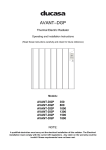
1
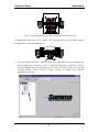
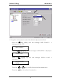
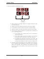
ADDENDUM
OPOS for contour cutting
1. INTRODUCTION
The SummaSign Series cutters have an accurate Optical POsitioning System
to guarantee precise contour cutting.
The OPOS can counterbalance the following irregularities:
1. ROTATED DESIGN : If the printed design is not loaded straight into the unit,
the contour can be rotated equally to fit the printed graphic.
2. SKEWED DESIGN : If the X and Y axes of the printed design are not
perpendicular, the contour can be skewed to fit the printed design.
3. INCORRECTLY SCALED DESIGN : If the print size is different from the original
design in your software due to media expansion or shrinkage, or due to
printing inaccuracies, the contour can be scaled to fit the printed
graphic.
1
Contour Cutting
Addendum
NOTE : The scaling can only be adjusted by a few percent.
à Between every set of 4 markers any combination of the three above
irregularities can be handled too.
• The parameter SPECIAL_LOAD in the user configuration menu determines
which alignment method is used: a Manual alignment method or OPOS.
This parameter can be changed with Summa Cutter Control or with the
control panel. Using Summa Cutter Control to select the desired
alignment method:
2
Contour Cutting
Addendum
• Using the control panel to select the desired alignment method:
Press the
key (MENU) until the message 'USER CONFIG 1' is
displayed on the LCD.
↓
←
USER CONFIG 1
→
Press the
↑↓
jogging key until the message ‘SYSTEM SETUP’ is displayed.
SYSTEM SETUP
Press the
displayed.
↵
jogging key until the message ‘SPECIAL LOAD’ is
↑↓ SPECIAL LOAD
← * OPOS
→
Press the
or
key to modify the special load parameter.
Press the
key to confirm the selection.
3
Contour Cutting
Addendum
2. CALIBRATING THE SYSTEM
The principle of OPOS is based on the principle of registrating black printed
markers around the design to know the exact position of the printout. The
registration of the markers is done by a sensor that is mounted at the bottom
of the cutting head. To be sure that OPOS works accurately the distance
between the sensor and the knife tip must be calibrated (OPOS calibration).
To make sure that the sensor is able to recognise the markers, a media
calibration can be performed.
The OPOS system has two calibration procedures:
n OPOS calibration
n Media calibration
1. OPOS CALIBRATION
The OPOS calibration fixes the exact distance between the knife tip and the
sensor. When noticing that the contour has shifted, it may be necessary to
perform another calibration test.
è To calibrate the optical system, proceed as follows:
• Power up the cutter and load a piece of black vinyl with a white
backing. The load procedure is described in the SummaSign User’s
Manual.
• Set the Origin on a clean, blank part of the vinyl. Defining the origin is
described in the SummaSign User’s Manual.
• Press the
key (MENU) key until the message ‘INTERNAL TESTS’ is
displayed on the LCD.
↓
• Press the
INTERNAL TESTS
jogging key until the message ‘ CAL OPOS’ is displayed.
↑
INTERNAL TESTS
↓
CAL. OPOS
↵
4
Contour Cutting
Press the
Addendum
key to confirm the selection.
The cutter will now cut out a rectangle.
• The message ‘WEED RECTANGLE’ will appear on the display:
WEED RECTANGLE
PRESS MENU
Weed carefully with tweezers the rectangle cut and press the
key.
The cutter will now measure the rectangle and set its calibration
parameters.
2. MEDIA CALIBRATION.
The OPOS is calibrated to work on a wide range of materials. However
certain types of material will not work with the default setup (high glossy
materials). The media calibration test will change the sensor value in such a
way that it is more reliable to sense the markers.
è To calibrate the media, proceed as follows:
• Print a black square of at least 4x4cm on the media with the ink that will
be used with OPOS.
• Power up the cutter and load the piece of media. The load procedure is
described in the SummaSign User’s Manual.
• Press the
key (MENU) key until the message ‘INTERNAL TESTS’ is
displayed on the LCD.
↓
• Press the
INTERNAL TESTS
jogging key until the message ‘ CAL OPOS’ is displayed.
↑
INTERNAL TESTS
↓
CAL. MEDIA
↵
5
Contour Cutting
• Press the
displayed.
Addendum
key to confirm the selection. The following message is
1
= SET
2
= MEASURE
• With the 1 option, the value can be set manually. This is useful when you
have already calibrated this kind of media and you know the value,
when the default needs to be set value back again. Otherwise choose 2
to proceed.
PUT ON WHITE
AREA
• Click the sensor down and use the arrow keys to place the sensor on top
of a white area. Press on the
key. The cutter will now sense the
white area and display the following message:
PUT ON BLACK
PRINTED AREA
• Use the arrow keys to place the sensor in the lower right part of the black
printed square. Press on the
key. The cutter will now sense the black
area.
• Normally a value will be displayed on the LCD:
VALUE : 38
This value is a specific value for this kind of media. It is advisable to
memorise this value. Later on, you can calibrate the media quickly by
setting this value manually instead of measuring it.
• An error message may appear. In this case the sensor is not able to
differentiate black and white. Make sure that the test has been
performed correctly. If OPOS in not able to sense the markers, the
manual alignment methods can be used.
6
Contour Cutting
Addendum
3. GENERAL (see section 6 for the actual procedure details)
The OPOS is based on the principle of the registration of black squares
printed around the design. The registration of the markers is done by a
sensor that is mounted at the bottom of the cutting head.
For accurate Contour Cutting with the alignment methods, proceed as
follows:
• Create the design on which you want to perform the contour cut.
• Place markers around your design.
• Print out the design with the markers.
• Load the printed design in the cutter and set the marker parameters.
• Execute the special load procedure.
• Cut out the contour.
NOTE
Most dedicated sign-making software will provide some easier ways to
do all this. Please contact your dealer. The description below supposes
that OPOS is not supported in you software. Otherwise contact your
software dealer.
7
Contour Cutting
Addendum
4. CREATING THE DESIGN
• Create in your software the design you want to print and Cut:
• Define the Contour:
⇒ Do not define the contour exactly on a printed line. This way it will
not catch the eye if the contour has moved a little during cutting.
⇒ Place the contour on a separate layer, assign a unique color to it,
etc. (refer to your software documentation), so that it is easy to
select the contour or the design.
• Make multiple copies if necessary (of both the design and the contour):
8
Contour Cutting
Addendum
5. PLACING THE MARKERS
• Place a marker indicating the origin.
X-Size
Y-Size
Origin
marker
White space
♦ The marker must be a black rectangle that has sizes which are
exactly known.
♦ It is advised to use square markers of 3mm. For markers of other
sizes (min: 1.2mm, max: 10mm) refer to the comments further in
this document. When using small sheets it may be better to use
smaller markers so that the loss of material will be less.
♦ Set the line style of the marker to none. A line style with a
certain thickness can influence the size of the markers.
♦ Make sure there is a white margin of about 3-4 times the marker
size around the marker. If anything is printed within this margin
the sensor may have trouble to locate the markers.
♦ Make sure that the origin marker is situated at the left side and
below all the contours that will be cut.
⇒ Place all the markers on a separate layer for easier handling.
⇒ Place a sign somewhere indicating the origin. This is useful when the
printed design needs to be loaded in the cutter.
9
Contour Cutting
Addendum
• Place the markers indicating the X-Axis.
X-Distance
♦ Place copies of the origin marker at a regular distance in the
horizontal direction.
♦ Maker sure that all markers are exactly at the same height.
♦ It is advisable to place markers along the complete design.
♦ Make sure there is enough white space around every marker.
♦ The advised X-distance depends on several items. Normally, 20
cm is a satisfying distance.
♦ If the marker size is smaller than 3 mm, it is advised to
lower this distance.
♦ If the white margin around the marker is not 3-4 times
the marker size is it advised to lower the X-distance.
♦ The bigger the X-Distance, the faster OPOS works. The
smaller the X-distance the more accurate OPOS works,
however the influence on the accuracy is rather small.
♦ The exact distance between the two markers must be known.
Do not measure these distances on the print out but measure
them in the software! The X-distance is the distance from the
lower left corner of one marker to the lower left corner of the
other marker.
10
Contour Cutting
Addendum
• Place the markers indicating the Y-axis:
Y-Distance
♦ Make a copy of the row of markers indicating the X-axis an
place them above the design.
♦ Make sure the two rows of markers are not shifted horizontally.
♦ The exact distance between the two rows must be known. Do
not measure these distances on the print-out, but measure them
in the software. The Y-distance is the distance from the lower
left corner from one marker to the lower left corner of the other
marker.
11
Contour Cutting
Addendum
6. PRINTING THE DESIGN
• Print the markers and the design with your printer (scaling = 100%).
• When printing on a roll, make sure that the orientation is as follows:
Origin marker
♦ Make sure that there is at least 1 cm, preferably 2cm margin
(0.4”, preferably 0.8”) on each side and in the front.
• When printing on sheets or cutting off your print from the roll, make sure
that there is a margin of at least 8 cm (3.15”) at the end of the sheet:
Origin marker
12
Contour Cutting
Addendum
7. LOADING THE CUTTER AND SETTING THE PARAMETERS
• Load the print out in the cutter as described in the User’s Manual. Make
sure that the marker indicating the origin is situated at the front right.
Origin marker
• Open Summa Cutter Control and select OPOS in the Configuration menu.
•
13
Contour Cutting
Addendum
♦ Fill in the values for the marker distances, sizes, quantities and
press OK. The number of markers is the number of markers in
one row (and not the number in both rows).
Range
X distance
Y distance
x size
y size
markers quantity
30 mm to 1300 mm
30 mm to 1300 mm
1.2 mm to 10 mm
1.2 mm to 10 mm
2 to 64
14
Contour Cutting
Addendum
8. REGISTRATING THE CROSS-MARKS
• Before proceeding, make sure all the cutting parameters are correct
(pressure, velocity, …). See User’s Manual.
• Press the
LCD.
key until the message ' SPECIAL LOAD' is displayed on the
SPECIAL LOAD
↵
•
•
Press
and the following message will appear on the LCD:
SET SENSOR ABOVE
FIRST MARKER
↵
Position the sensor (
) exactly above the origin-marker using the
,
,
,
jogging keys.
•
Click the sensor box down. When using a drag head turn on the
metallic knob situated on the lower side of the head. For a tangential
head simply click it down manually.
•
Press the
•
The cutter will now scan the markers and store the origin. In case
something may have gone wrong the following message will be
displayed : ‘ ERROR: MARKERS NOT SENSED PROPERLY’
key to confirm the selected point of origin.
15
Contour Cutting
Addendum
9. CUTTING THE CONTOUR
• Follow the specific instructions for contour cutting in your software. If
there are no such instructions, follow the explanation below.
• Move the entire design (cross-marks and contours included) in your
software so that the origin mark is situated in the lower left corner of the
cutting area (In most sign-making software the orientation is landscape. If
not, you will have to rotate everything).
• Select the contours and cut them out:
♦ Make sure that only the contours are cut.
♦ Make sure that the origin of the cutting area is used.
⇒ Some software will shift the selected contours to the origin when
cutting. This can be avoided by adding a small rectangle that has its
lower left corner right in the origin. Select this rectangle together
with the contours.
16
Contour Cutting
Addendum
Correct
Incorrect
Origin
Origin
17